UG149: Si5344H Evaluation Board User's Guide - Silicon Labs
←
→
Page content transcription
If your browser does not render page correctly, please read the page content below
UG149: Si5344H Evaluation Board User’s
Guide
The Si5344H-EVB is used for evaluating the Si5344H Any-Frequency, Any-Output, Jit-
ter Attenuating Clock Multiplier. The Si5344H combines 4th generation DSPLL and Mul- EVB FEATURES:
tisynth™ technologies to enable any-frequency clock generation for applications that
require the highest level of jitter performance. The Si5344H-EVB has two independent • Powered from USB port or external power
input clocks and four independent output clocks. The Si5344H-EVB can be controlled supply.
and configured using the ClockBuilder® Pro (CBPro) software tool. • Onboard 48 MHz XTAL or Reference SMA
Inputs allow holdover mode of operation
on the Si5344H.
• CBPro GUI-programmable VDD supply
allows the device to operate from 3.3, 2.5,
or 1.8 V.
• CBPro GUI-programmable VDDO supplies
allow each of the ten outputs to have its
own supply voltage, selectable from 3.3,
2.5, or 1.8 V.
• CBPro GUI-controlled voltage, current,
and power measurements of VDD and all
VDDO supplies.
• Status LEDs for power supplies and
control/status signals of Si5344H.
• SMA connectors for input clocks, output
clocks, and optional external timing
reference clock.
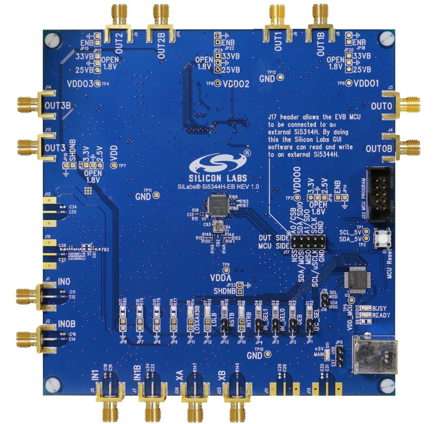
Si5344H Evaluation Board
Skyworks Solutions, Inc. • Phone [781] 376-3000 • Fax [781] 376-3100 • sales@skyworksinc.com • www.skyworksinc.com
1 Rev. 1.1 • Skyworks Proprietary Information • Products and Product Information are Subject to Change Without Notice • July 26, 2021 1
UG149: Si5344H Evaluation Board User’s Guide • Overview

1. Overview

1.1 Functional Block Diagram

A functional block diagram of the Si5344H-EVB is shown below. This EVB can be connected to a PC via the main USB connector
for programming, control, and monitoring. See Section 1.2 Si5344H EVB Support Documentation or Section 1.3 Quick Start for more
information.

       Main USB                     Power only
                                                     +5V_USB
       Connector

        Ext +5V
                                                             Power Supply
                                                     +5V_Ext
       Connector

                                                                     VDD_Core

                                                                                VDD_3.3

                                                                                          VDDO_0
                                                                                          VDDO_1
                                                                                          VDDO_2
                                                                                          VDDO_3
                                                     VDDMCU
                                                     I2C/SPI Bus

                                                                                VDD_3.3

                                                                                          VDDO_0
                                                                                          VDDO_1
                                                                                          VDDO_2
                                                                                          VDDO_3
                                                     I2C/SPI Bus     VDD_Core

                C8051F380                              Control/
                   MCU                                  Status

                     +
                Peripherals                           INTR
                                                      Alarm_Status

                                    48 MHz           XA
                                                                   Si5344H
                                     XTAL            XB

      Input Clock 0   {            Input
                                Termination
                                                     IN_0
                                                     IN_0B
                                                                                              OUT_0
                                                                                              OUT_0B
                                                                                                         Output
                                                                                                       Termination         }   Output Clock 0

      Input Clock 1   {            Input
                                Termination
                                                     IN_1
                                                     IN_1B
                                                                                              OUT_1
                                                                                              OUT_1B
                                                                                                         Output
                                                                                                       Termination         }   Output Clock 1

                                                                                                                           }
                                                                                              OUT_2      Output
                                                                                                       Termination             Output Clock 2
                                                                                              OUT_2B
                                                                                              OUT_3
                                                                                              OUT_3B
                                                                                                         Output
                                                                                                       Termination         }   Output Clock 3

                                          Figure 1.1. Si5344H-EVB Functional Block Diagram

1.2 Si5344H EVB Support Documentation

The Si5344H EVB Schematic and Bill of Materials (BOM) can be found online at: http://www.silabs.com/products/clocksoscillators/pa-
ges/si538x-4x-evb.aspx. Contact Silicon labs for related user's guides, data sheets, and software.

Note: The Si5344H EVB schematic is in OrCad Capture hierarchical format and not in a typical “flat” schematic format.

             Skyworks Solutions, Inc. • Phone [781] 376-3000 • Fax [781] 376-3100 • sales@skyworksinc.com • www.skyworksinc.com
2       Rev. 1.1 • Skyworks Proprietary Information • Products and Product Information are Subject to Change Without Notice • July 26, 2021     2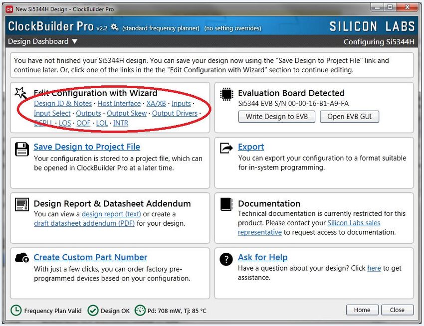
UG149: Si5344H Evaluation Board User’s Guide • Overview

1.3 Quick Start

    1. Install ClockBuilder Pro desktop software: http://www.silabs.com/CBPro.
        • Installation instructions and the user’s guide for ClockBuilder Pro can also be found at the download link shown above.
    2. Connect a USB cable from the Si5344H-EVB to the PC where the software is installed.
    3. Confirm jumpers are installed as shown in Table 1.1 Si5344H EVB Jumper Defaults on page 3.
    4. Launch the ClockBuilder Pro software.
    5. You can use ClockBuilder Pro to create, download, and run a frequency plan on the Si5344H-EVB.
    6. Contact Silicon Labs for the Si5344H data sheet.

1.4 Jumper Defaults

                                                   Table 1.1. Si5344H EVB Jumper Defaults

        Location                  Type                 I = Installed               Location                   Type                 I = Installed

                                                        0 = Open                                                                    0 = Open

          JP1                     2 pin                      I                        JP14                    2 pin                      O

          JP2                     2 pin                      I                        JP15                    2 pin                      O

          JP3                     2 pin                      I                        JP16                    3 pin                  all open

          JP4                     2 pin                      I                        JP17                    3 pin                  all open

          JP5                     3 pin                   1 to 2                      JP18                    2 pin                      O

          JP6                     2 pin                      O                        JP19                    2 pin                      O

          JP7                     2 pin                      O                        JP20                    3 pin                  all open

          JP8                     2 pin                      O                        JP21                    3 pin                  all open

          JP9                     2 pin                      O                        JP22                    2 pin                      O

          JP10                    2 pin                      O                        JP23                    2 pin                      O

          JP11                    2 pin                      O                        JP24                    3 pin                  all open

          JP12                    2 pin                      O

          JP13                    2 pin                      O                        JP17                   5x2 Hdr              All 5 installed

Note:
 1. Refer to the Si5344H EVB Schematics for the functionality associated with each jumper.

               Skyworks Solutions, Inc. • Phone [781] 376-3000 • Fax [781] 376-3100 • sales@skyworksinc.com • www.skyworksinc.com
3         Rev. 1.1 • Skyworks Proprietary Information • Products and Product Information are Subject to Change Without Notice • July 26, 2021       3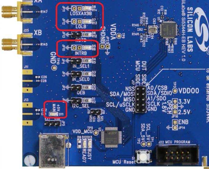
UG149: Si5344H Evaluation Board User’s Guide • Overview

1.5 Status LEDs

                                                   Table 1.2. Si5344H EVB Status LEDs

            Location                            Silkscreen                              Color                     Status Function Indication

               D5                                  INTRB                                 Blue                  DUT Interrupt

               D7                                  LOLB                                  Blue                  DUT Loss of Lock

               D8                               LOSXAXBB                                 Blue                  DUT Loss of Reference

               D11                               +5V MAIN                               Green                  Main USB +5 V present

               D12                                READY                                 Green                  MCU Ready

               D13                                 BUSY                                 Green                  MCU Busy

D11 is illuminated when USB +5 V supply voltage is present. D12 and D13 are status LEDs showing on-board MCU activity.

                                                           Figure 1.2. Status LEDs

             Skyworks Solutions, Inc. • Phone [781] 376-3000 • Fax [781] 376-3100 • sales@skyworksinc.com • www.skyworksinc.com
4       Rev. 1.1 • Skyworks Proprietary Information • Products and Product Information are Subject to Change Without Notice • July 26, 2021    4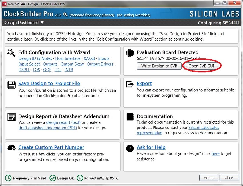
UG149: Si5344H Evaluation Board User’s Guide • Overview

1.6 External Reference Input (XA/XB)

An external reference (XTAL) is used in combination with the internal oscillator to produce an ultra-low jitter reference clock for the
DSPLL and for providing a stable reference for the free-run and holdover modes. The Si5344H-EVB can also accommodate an external
reference clock instead of a crystal. To evaluate the device with a REFCLK, C93 and C94 must be populated and the XTAL removed
(see the figure below). The REFCLK can then be applied to J25 and J26.

                                               Figure 1.3. External Reference Input Circuit

1.7 Clock Input Circuits (INx/INxB and FB-IN/FB-INB)

The Si5344H-EVB has four SMA connectors (IN0/IN0B and IN1/IN1B) for receiving external clock signals. All input clocks are termina-
ted, as shown in the figure below.

Input clocks are AC coupled and 50 W terminated. This represents four differential input clock pairs. Single-ended clocks can be used
by appropriately driving one side of the differential pair with a single-ended clock. See the Si5344H data sheet for details on how to
configure inputs as single-ended.

                                                Figure 1.4. Input Clock Termination Circuit

             Skyworks Solutions, Inc. • Phone [781] 376-3000 • Fax [781] 376-3100 • sales@skyworksinc.com • www.skyworksinc.com
5       Rev. 1.1 • Skyworks Proprietary Information • Products and Product Information are Subject to Change Without Notice • July 26, 2021   5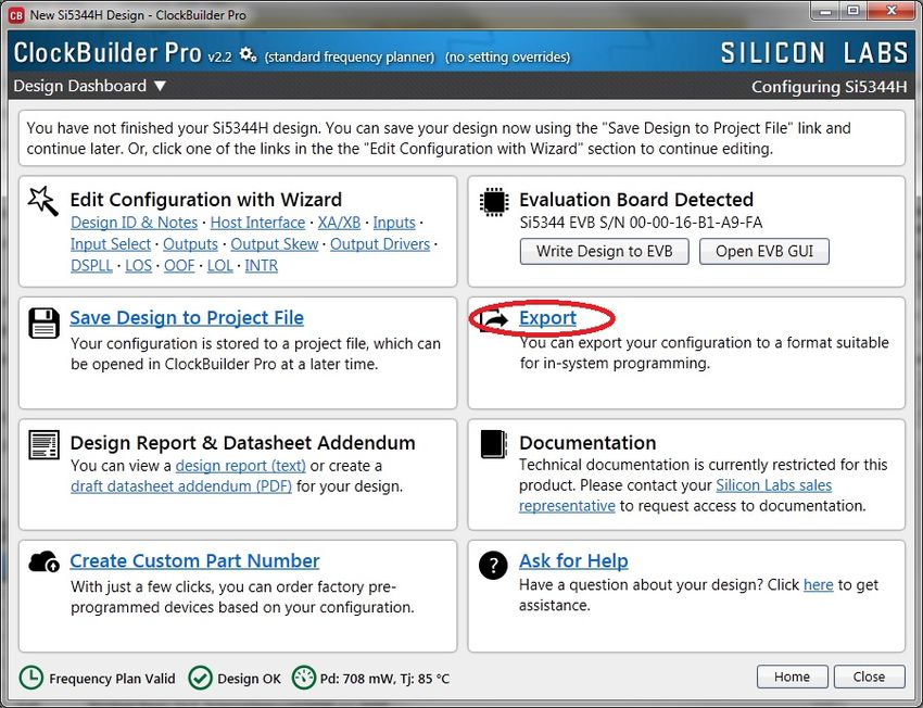
UG149: Si5344H Evaluation Board User’s Guide • Overview

1.8 Clock Output Circuits (OUTx/OUTxB)

Each of the eight outputs (four differential pairs) is AC coupled to its respective SMA connector. The output clock termination circuit is
shown in the figure below. The output signal has no DC bias. If DC coupling is required, the AC coupling capacitors can be replaced
with a resistor of appropriate value. The Si5344H-EVB provides pads for optional output termination resistors and/or low frequency
capacitors.

Note: Components with schematic “NI” designation are not normally populated on the Si5344H-EVB and provide locations on the PCB
for optional DC/AC terminations by the end user.

                                              Figure 1.5. Output Clock Termination Circuit

             Skyworks Solutions, Inc. • Phone [781] 376-3000 • Fax [781] 376-3100 • sales@skyworksinc.com • www.skyworksinc.com
6       Rev. 1.1 • Skyworks Proprietary Information • Products and Product Information are Subject to Change Without Notice • July 26, 2021   6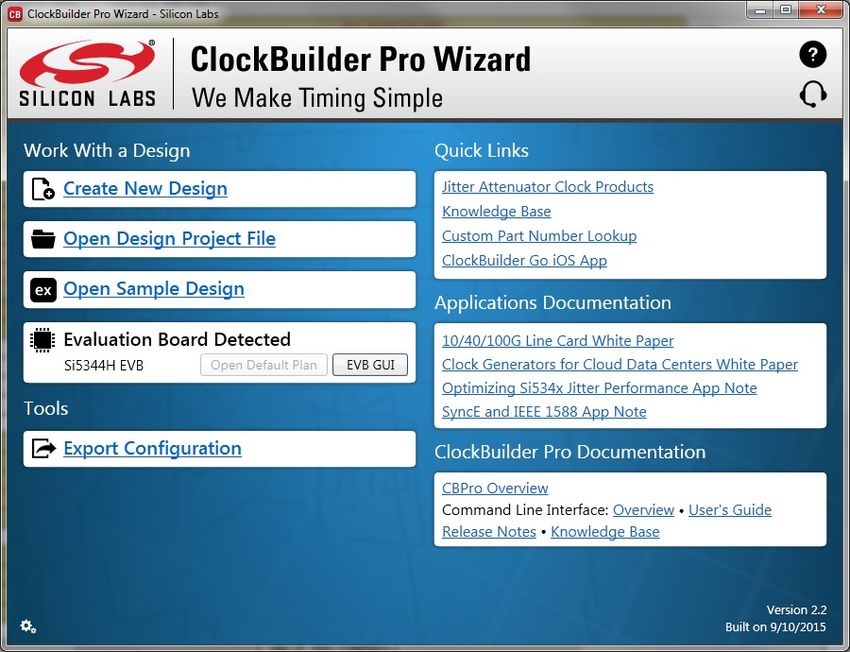
UG149: Si5344H Evaluation Board User’s Guide • Using Si5344H EVB

2. Using Si5344H EVB

2.1 Connecting the EVB to Your Host PC

Once ClockBuilder Pro software is installed, connect the software to the EVB with a USB cable, as shown in the figure below.

                                                   Figure 2.1. EVB Connection Diagram

             Skyworks Solutions, Inc. • Phone [781] 376-3000 • Fax [781] 376-3100 • sales@skyworksinc.com • www.skyworksinc.com
7       Rev. 1.1 • Skyworks Proprietary Information • Products and Product Information are Subject to Change Without Notice • July 26, 2021   7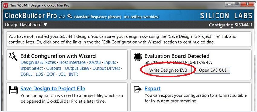
UG149: Si5344H Evaluation Board User’s Guide • Using Si5344H EVB

2.2 Main Features of ClockBuilder Pro Applications

The ClockBuilder Pro installer installs two main applications: the ClockBuilder Pro Wizard and the EVB GUI.

                                          Figure 2.2. Application #1: ClockBuilder Pro Wizard

Use the CBPro Wizard to do the following:
• Create a new design.
• Review or edit an existing design.
• Export: create in-system programming.

                                                    Figure 2.3. Application #2: EVB GUI

Use the EVB GUI to do the following:
• Download configuration to EVB’s DUT (Si5344H).
• Control the EVB’s regulators.
• Monitor voltage, current, power on the EVB.

             Skyworks Solutions, Inc. • Phone [781] 376-3000 • Fax [781] 376-3100 • sales@skyworksinc.com • www.skyworksinc.com
8       Rev. 1.1 • Skyworks Proprietary Information • Products and Product Information are Subject to Change Without Notice • July 26, 2021   8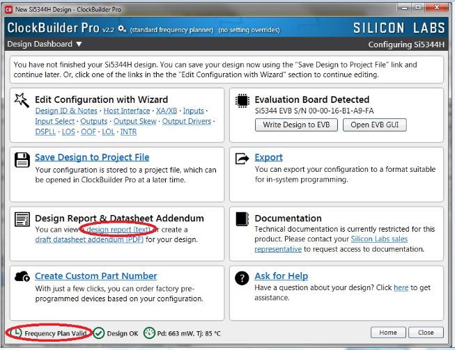
UG149: Si5344H Evaluation Board User’s Guide • Using Si5344H EVB

2.3 Common ClockBuilder Pro Workflow Scenarios

There are three common workflow scenarios when using CBPro and the Si5344H EVB. These workflow scenarios are as follows:

Workflow Scenario #1:           Testing a Silicon Labs-created Default Configuration

Workflow Scenario #2:           Modifying the Default Silicon Labs-created Device Configuration

Workflow Scenario #3:           Testing a User-created Device Configuration

Each scenario is described in more detail in the following sections.

             Skyworks Solutions, Inc. • Phone [781] 376-3000 • Fax [781] 376-3100 • sales@skyworksinc.com • www.skyworksinc.com
9       Rev. 1.1 • Skyworks Proprietary Information • Products and Product Information are Subject to Change Without Notice • July 26, 2021   9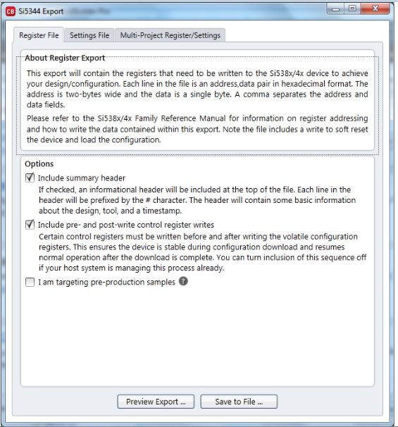
UG149: Si5344H Evaluation Board User’s Guide • Using Si5344H EVB

2.3.1 Workflow Scenario #1: Testing a Silicon Labs Created Default Configuration

The flow for using the EVB GUI to initialize and control a device on the EVB is as follows.
  1. Once the PC and EVB are connected, launch ClockBuilder Pro by clicking on this icon on your PC’s desktop.

                                                       Figure 2.4. ClockBuilder Pro Desktop Icon

     2. When the EVB is detected, select the "Open Default Plan" button on the Wizard’s main menu. CBPro automatically detects the
        EVB and device type.

                                                              Figure 2.5. Open Default Plan

     3. Once you open the default plan (based on your EVB model number), a popup window opens.

                                                         Figure 2.6. Write Design to EVB Dialog

               Skyworks Solutions, Inc. • Phone [781] 376-3000 • Fax [781] 376-3100 • sales@skyworksinc.com • www.skyworksinc.com
10        Rev. 1.1 • Skyworks Proprietary Information • Products and Product Information are Subject to Change Without Notice • July 26, 2021   10
UG149: Si5344H Evaluation Board User’s Guide • Using Si5344H EVB
4. Select "Yes" to write the default plan to the Si5344H device mounted on your EVB. This ensures the device is completely
reconfigured per the Silicon Labs default plan for the DUT type mounted on the EVB.
Figure 2.7. Writing Design Status
5. After CBPro writes the default plan to the EVB, select "Open EVB GUI".
Figure 2.8. Open EVB GUI
Skyworks Solutions, Inc. • Phone [781] 376-3000 • Fax [781] 376-3100 • sales@skyworksinc.com • www.skyworksinc.com
11 Rev. 1.1 • Skyworks Proprietary Information • Products and Product Information are Subject to Change Without Notice • July 26, 2021 11UG149: Si5344H Evaluation Board User’s Guide • Using Si5344H EVB
6. The EVB GUI opens. All power supplies are set to the values defined in the device’s default CBPro project file created by Silicon
Labs, as shown in the figure below.
Figure 2.9. EVB GUI Window
Verify Free-run Mode Operation
Assuming no external clocks have been connected to the INPUT CLOCK differential SMA connectors (labeled “INx/INxB”) located
around the perimeter of the EVB, the DUT should now be operating in free-run mode, as the DUT will be locked to the crystal in this
case.
You can run a quick check to determine if the device is powered up and generating output clocks (and consuming power) by clicking
on the "Read All" button (bottom right-hand corner of Figure 2.9 EVB GUI Window on page 12) and then reviewing the voltage, current,
and power readings for each VDDx supply.
Note: Shutting the VDD and VDDA power supplies “Off” and then “On” will power-down and reset the DUT. Every time you do this,
to reload the Silicon Labs-created default plan into the DUT’s register space, you must go back to the Wizard’s main menu and select
"Write Design to EVB".
Figure 2.10. Write Design to EVB
Failure to do the step above will cause the device to read in a pre-programmed plan from its non-volatile memory (NVM). However, the
plan loaded from the NVM may not be the latest plan recommended by Silicon Labs for evaluation.
Skyworks Solutions, Inc. • Phone [781] 376-3000 • Fax [781] 376-3100 • sales@skyworksinc.com • www.skyworksinc.com
12 Rev. 1.1 • Skyworks Proprietary Information • Products and Product Information are Subject to Change Without Notice • July 26, 2021 12UG149: Si5344H Evaluation Board User’s Guide • Using Si5344H EVB
At this point, you should verify the presence and frequencies of the output clocks (running in free-run mode from the crystal) using
appropriate external instrumentation connected to the output clock SMA connectors. To verify the output clocks are toggling at the
correct frequency and signal format, click on "View Design Report" as highlighted in the figure below.
Figure 2.11. View Design Report
Your configuration’s design report opens in a new window, as shown in the figure below. Compare the observed output clocks to the
frequencies and formats noted in your default project’s Design Report.
Skyworks Solutions, Inc. • Phone [781] 376-3000 • Fax [781] 376-3100 • sales@skyworksinc.com • www.skyworksinc.com
13 Rev. 1.1 • Skyworks Proprietary Information • Products and Product Information are Subject to Change Without Notice • July 26, 2021 13UG149: Si5344H Evaluation Board User’s Guide • Using Si5344H EVB
Figure 2.12. Design Report Window
Verify Locked Mode Operation
Assuming you connect the correct input clocks to the EVB (as noted in the Design Report shown above), the DUT on your EVB will be
running in “locked” mode.
Skyworks Solutions, Inc. • Phone [781] 376-3000 • Fax [781] 376-3100 • sales@skyworksinc.com • www.skyworksinc.com
14 Rev. 1.1 • Skyworks Proprietary Information • Products and Product Information are Subject to Change Without Notice • July 26, 2021 14UG149: Si5344H Evaluation Board User’s Guide • Using Si5344H EVB
2.3.2 Workflow Scenario #2: Modifying the Default Silicon Labs Created Device Configuration
1. To modify the “default” configuration using the CBPro Wizard, select "Edit Configuration with Wizard".
Figure 2.13. Edit Configuration with Wizard
Skyworks Solutions, Inc. • Phone [781] 376-3000 • Fax [781] 376-3100 • sales@skyworksinc.com • www.skyworksinc.com
15 Rev. 1.1 • Skyworks Proprietary Information • Products and Product Information are Subject to Change Without Notice • July 26, 2021 15UG149: Si5344H Evaluation Board User’s Guide • Using Si5344H EVB
2. You will now be taken to the Wizard’s step-by-step menus to allow you to change any of the default plan’s operating configurations.
Figure 2.14. Design Wizard
Note: You can click on the icon on the lower left hand of the menu to confirm that your frequency plan is valid. After making your
desired changes, you can click on "Write to EVB" to update the DUT to reconfigure your device in real-time. The Design Write
status window opens each time you make a change.
Figure 2.15. Writing Design Status
Skyworks Solutions, Inc. • Phone [781] 376-3000 • Fax [781] 376-3100 • sales@skyworksinc.com • www.skyworksinc.com
16 Rev. 1.1 • Skyworks Proprietary Information • Products and Product Information are Subject to Change Without Notice • July 26, 2021 16UG149: Si5344H Evaluation Board User’s Guide • Using Si5344H EVB
2.3.3 Workflow Scenario #3: Testing a User Created Device Configuration
1. To test a previously-created user configuration, open the CBPro Wizard by clicking the icon on your desktop and then selecting
"Open Design Project File".
Figure 2.16. pen Design Project File
2. Locate your CBPro design file (*.slabtimeproj or *.sitproj file) design file in the Windows file browser.
Figure 2.17. Browse to Project File
Skyworks Solutions, Inc. • Phone [781] 376-3000 • Fax [781] 376-3100 • sales@skyworksinc.com • www.skyworksinc.com
17 Rev. 1.1 • Skyworks Proprietary Information • Products and Product Information are Subject to Change Without Notice • July 26, 2021 17UG149: Si5344H Evaluation Board User’s Guide • Using Si5344H EVB
3. Select "Yes" when the WRITE DESIGN to EVB popup appears:
Figure 2.18. Write Design to EVB Dialog
4. The progress bar is launched. Once the new design project file has been written to the device, verify the presence and frequencies
of your output clocks and other operating configurations using external instrumentation.
Skyworks Solutions, Inc. • Phone [781] 376-3000 • Fax [781] 376-3100 • sales@skyworksinc.com • www.skyworksinc.com
18 Rev. 1.1 • Skyworks Proprietary Information • Products and Product Information are Subject to Change Without Notice • July 26, 2021 18UG149: Si5344H Evaluation Board User’s Guide • Using Si5344H EVB
2.4 Exporting the Register Map File for Device Programming by a Host Processor
You can also export your configuration to a file format suitable for in-system programming by selecting "Export", as shown in the figure
below.
Figure 2.19. Export Register Map File
You can now write your device’s complete configuration to file formats suitable for in-system programming.
Skyworks Solutions, Inc. • Phone [781] 376-3000 • Fax [781] 376-3100 • sales@skyworksinc.com • www.skyworksinc.com
19 Rev. 1.1 • Skyworks Proprietary Information • Products and Product Information are Subject to Change Without Notice • July 26, 2021 19UG149: Si5344H Evaluation Board User’s Guide • Using Si5344H EVB
Figure 2.20. Export Settings
Skyworks Solutions, Inc. • Phone [781] 376-3000 • Fax [781] 376-3100 • sales@skyworksinc.com • www.skyworksinc.com
20 Rev. 1.1 • Skyworks Proprietary Information • Products and Product Information are Subject to Change Without Notice • July 26, 2021 20UG149: Si5344H Evaluation Board User’s Guide • Writing A New Frequency Plan or Device Configuration to Non-volatile Memory (OTP)
3. Writing A New Frequency Plan or Device Configuration to Non-volatile Memory (OTP)
Note: Writing to the device non-volatile memory (OTP) is NOT the same as writing a configuration into the Si5344H using ClockBuilder
Pro on the Si5344H EVB. Writing a configuration into the EVB from ClockBuilder Pro is done using Si5344H RAM space and can be
done virtually unlimited number of times. Writing to OTP is limited, as described below.
Refer to the Si534x/8x Family Reference Manuals and device datasheets for information on how to write a configuration to the EVB
DUT’s non-volatile memory (OTP). The OTP can only be programmed a maximum of two times. Care must be taken to ensure the
configuration desired is valid when choosing to write to OTP.
Skyworks Solutions, Inc. • Phone [781] 376-3000 • Fax [781] 376-3100 • sales@skyworksinc.com • www.skyworksinc.com
21 Rev. 1.1 • Skyworks Proprietary Information • Products and Product Information are Subject to Change Without Notice • July 26, 2021 21UG149: Si5344H Evaluation Board User’s Guide • Serial Device Communications (Si5344H ↔ MCU)
4. Serial Device Communications (Si5344H ↔ MCU)
4.1 On-Board SPI Support
The MCU on-board the Si5344H-EVB communicates with the Si5344H device through a 4-wire SPI (Serial Peripheral Interface) link.
The MCU is the SPI master and the Si5344H device is the SPI slave. The Si5344H device can also support a 2-wire I2C serial
interface, although the Si5344H-EVB does NOT support the I2C mode of operation. SPI mode was chosen for the EVB because of the
relatively higher speed transfers supported by SPI vs. I2C.
4.2 External I2C Support
I2C can be supported if driven from an external I2C controller. The serial interface signals between the MCU and Si5344H pass through
shunts loaded on header J17. These jumper shunts must be installed in J17 for normal EVB operation using SPI with CBPro. If testing
of I2C operation via external controller is desired, the shunts in J17 can be removed thereby isolating the on-board MCU from the
Si5344H device. The shunt at JP1 (I2C_SEL) must also be removed to select I2C as Si5344H interface type. An external I2C controller
connected to the Si5344H side of J17 can then communicate to the Si5344H device. (For more information on I2C signal protocol,
please refer to the Si5344H data sheet.)
The figure below illustrates the J17 header schematic. J17 even numbered pins (2, 4, 6, etc.) connect to the Si5344H device and the
odd numbered pins (1, 3, 5, etc.) connect to the MCU. Once the jumper shunts have been removed from J17 and JP1, I2C operation
should use J17 pin 4 (DUT_SDA_SDIO) as the I2C SDA and J17 pin 8 (DUT_SCLK) as the I2C SCLK. Please note the external I2C
controller will need to supply its own I2C signal pull-up resistors.
Figure 4.1. Serial Communications Header J17
Skyworks Solutions, Inc. • Phone [781] 376-3000 • Fax [781] 376-3100 • sales@skyworksinc.com • www.skyworksinc.com
22 Rev. 1.1 • Skyworks Proprietary Information • Products and Product Information are Subject to Change Without Notice • July 26, 2021 22ClockBuilder Pro
Customize Skyworks clock generators,
jitter attenuators and network
synchronizers with a single tool. With
CBPro you can control evaluation
boards, access documentation, request
a custom part number, export for
in-system programming and more!
www.skyworksinc.com/CBPro
Portfolio SW/HW Quality Support & Resources
www.skyworksinc.com/ia/timing www.skyworksinc.com/CBPro www.skyworksinc.com/quality www.skyworksinc.com/support
Copyright © 2021 Skyworks Solutions, Inc. All Rights Reserved.
Information in this document is provided in connection with Skyworks Solutions, Inc. (“Skyworks”) products or services. These materials, including the
information contained herein, are provided by Skyworks as a service to its customers and may be used for informational purposes only by the customer.
Skyworks assumes no responsibility for errors or omissions in these materials or the information contained herein. Skyworks may change its documentation,
products, services, specifications or product descriptions at any time, without notice. Skyworks makes no commitment to update the materials or
information and shall have no responsibility whatsoever for conflicts, incompatibilities, or other difficulties arising from any future changes.
No license, whether express, implied, by estoppel or otherwise, is granted to any intellectual property rights by this document. Skyworks assumes no liability
for any materials, products or information provided hereunder, including the sale, distribution, reproduction or use of Skyworks products, information or
materials, except as may be provided in Skyworks’ Terms and Conditions of Sale.
THE MATERIALS, PRODUCTS AND INFORMATION ARE PROVIDED “AS IS” WITHOUT WARRANTY OF ANY KIND, WHETHER EXPRESS, IMPLIED, STATUTORY, OR
OTHERWISE, INCLUDING FITNESS FOR A PARTICULAR PURPOSE OR USE, MERCHANTABILITY, PERFORMANCE, QUALITY OR NON-INFRINGEMENT OF ANY
INTELLECTUAL PROPERTY RIGHT; ALL SUCH WARRANTIES ARE HEREBY EXPRESSLY DISCLAIMED. SKYWORKS DOES NOT WARRANT THE ACCURACY OR
COMPLETENESS OF THE INFORMATION, TEXT, GRAPHICS OR OTHER ITEMS CONTAINED WITHIN THESE MATERIALS. SKYWORKS SHALL NOT BE LIABLE FOR
ANY DAMAGES, INCLUDING BUT NOT LIMITED TO ANY SPECIAL, INDIRECT, INCIDENTAL, STATUTORY, OR CONSEQUENTIAL DAMAGES, INCLUDING WITHOUT
LIMITATION, LOST REVENUES OR LOST PROFITS THAT MAY RESULT FROM THE USE OF THE MATERIALS OR INFORMATION, WHETHER OR NOT THE RECIPIENT
OF MATERIALS HAS BEEN ADVISED OF THE POSSIBILITY OF SUCH DAMAGE.
Skyworks products are not intended for use in medical, lifesaving or life-sustaining applications, or other equipment in which the failure of the Skyworks
products could lead to personal injury, death, physical or environmental damage. Skyworks customers using or selling Skyworks products for use in such
applications do so at their own risk and agree to fully indemnify Skyworks for any damages resulting from such improper use or sale.
Customers are responsible for their products and applications using Skyworks products, which may deviate from published specifications as a result of
design defects, errors, or operation of products outside of published parameters or design specifications. Customers should include design and operating
safeguards to minimize these and other risks. Skyworks assumes no liability for applications assistance, customer product design, or damage to any
equipment resulting from the use of Skyworks products outside of Skyworks’ published specifications or parameters.
Skyworks, the Skyworks symbol, Sky5®, SkyOne®, SkyBlue™, Skyworks Green™, Clockbuilder®, DSPLL®, ISOmodem®, ProSLIC®, and SiPHY® are trademarks or
registered trademarks of Skyworks Solutions, Inc. or its subsidiaries in the United States and other countries. Third-party brands and names are for
identification purposes only and are the property of their respective owners. Additional information, including relevant terms and conditions, posted at
www.skyworksinc.com, are incorporated by reference.
Skyworks Solutions, Inc. | Nasdaq: SWKS | sales@skyworksinc.com | www.skyworksinc.com
USA: 781-376-3000 | Asia: 886-2-2735 0399 | Europe: 33 (0)1 43548540 |You can also read