Protocol Signaling Procedures in LTE - By: V. Srinivasa Rao, Senior Architect & Rambabu Gajula, Lead Engineer
←
→
Page content transcription
If your browser does not render page correctly, please read the page content below
White Paper
Protocol Signaling Procedures in LTE
By: V. Srinivasa Rao, Senior Architect & Rambabu Gajula, Lead Engineer
Overview CONTENTS
The exploding growth of the internet and associated services has fueled Network Architecture pg. 2
the need for more and more bandwidth. Handheld devices are growing
Bearers in LTE pg. 2
exponentially and thus the need for the services on the move has increased
tremendously. Current 3G technology is able to cope with the demand to System Information Broadcasting pg. 3
some extent but unable to satisfy the needs completely.
Tracking Area Update pg. 7
Long Term Evolution (LTE) promises higher data rates, 100Mbps in the
Mobile-Originated Data Call pg. 8
downlink and 50Mbps in the uplink in LTE’s first phase, and will reduce the
data plane latency and supports interoperability with other technologies Mobile Initiated Data Call Termination pg. 9
such as GSM, GPRS and UMTS. Plus, LTE has support for scalable bandwidth,
Paging pg. 9
from 1.25MHz to 20MHz. All these features make LTE a very attractive
technology for operators as well as the subscribers. Mobile Terminated Data Call pg. 10
In this paper we briefly touch upon the procedures executed by LTE user Conclusion pg. 10
equipment (UE) and the various LTE network elements in order to provide
References pg. 11
the services requested by the UE.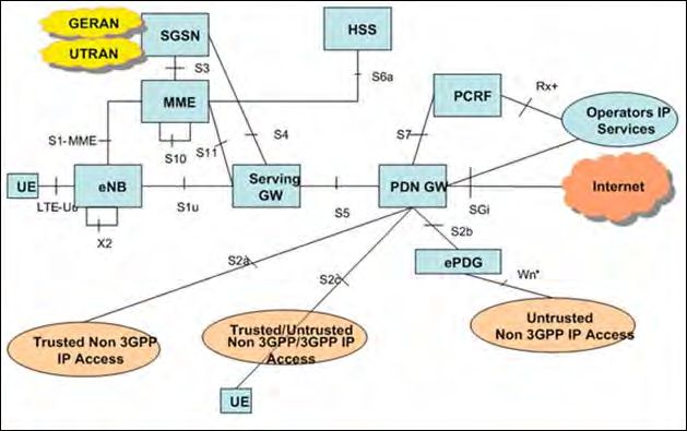
Protocol Signaling Procedures in LTE | Radisys White Paper 2
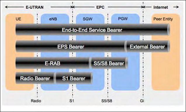
Network Architecture
In Figure 1, the architecture of the LTE network is
given with the various interfaces between the network
elements; GERAN and UTRAN networks are shown
for completeness.
The functions of the various network elements are:
• eNodeB: Radio Resource Management functions,
IP header compression, encryption of user data
streams, selection of an MME, routing of user plane
data to S-GW, scheduling and transmission of
paging message.
• MME: NAS signaling (eMM, eSM) and security,
AS security, tracking area list management, PDN
GW and S-GW selection, handovers (intra- and Figure 1. LTE Network Architecture
inter-LTE), authentication, bearer management.
• S-GW: The local mobility anchor point for inter-
eNodeB handover; downlink packet buffering and
initiation of network-triggered service requests,
lawful interception, accounting on user and QCI
granularity, UL/DL charging per UE.
• P-GW: UE IP address allocation, packet filtering
and PDN connectivity, UL and DL service-level
charging, gating and rate enforcement.
Figure 2 shows the protocol stacks at various
LTE network elements. Figure 2. LTE Control/User Plane Protocol Stacks
Bearers in LTE
In LTE, end-to-end bearers are realized by the EPS
bearers, which are a collection of radio, S1 and S5/S8
bearers. An EPS bearer identity uniquely identifies an
EPS bearer for one UE accessing via E-UTRAN. The
EPS Bearer Identity is allocated by the MME and is
the one that carries the information; usually it carries
the user data.
There are three kinds of bearers in LTE: Radio Bearers,
S1 Bearers and EPS Bearers as depicted in the Figure 3.
In the UE, the uplink TFT maps a traffic flow aggregate
to an EPS bearer in the uplink direction and in PGW the
downlink TFT maps a traffic flow aggregate to an EPS
bearer in the downlink direction. There is much more
Figure 3. LTE Bearer Architecture
complexity than what is summarized here, but for
brevity’s sake it suffices to say that traffic off-loaders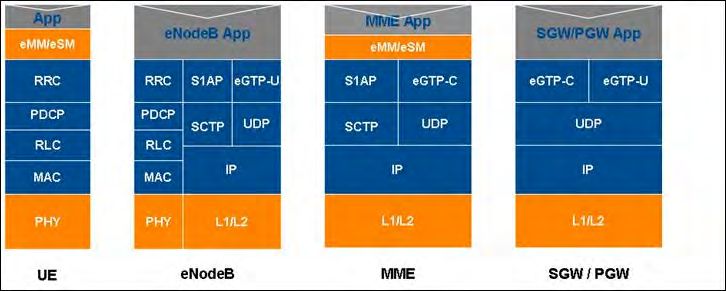
Protocol Signaling Procedures in LTE | Radisys White Paper                                3

classify traffic streams using DPI and then, based on
the operator’s policies, offload part of the traffic directly
onto the Internet while sending the remaining traffic
to the core network. Traffic off-loaders typically will
be deployed as “bump-in-the-wire” boxes between the
radio access network (RAN) and the core network (CN);
in the future, some Radio Network Controllers (RNCs)
might include this functionality inside the box.
• Radio Bearer: A radio bearer transports the packets
  of an EPS bearer between the UE and an eNodeB.
                                                                Figure 4. System Information Broadcast
• S1 Bearer: An S1 bearer transports the packets
  of an EPS bearer between an eNodeB and a S-GW.
• S5/S8 Bearer: An S5/S8 bearer transports the
  packets of an EPS bearer between the S-GW
  and the PDN GW.

There is a one-to-one mapping between radio,
S1 and S5/S8 bearers; this end-to-end EPS bearer
realizes the negotiated QoS for the service.

System Information                                              Figure 5. MME Configuration Update Procedure

Broadcasting
To get service from the network, a UE has to select             • MIB contains cell bandwidth and information
the network and camp on a cell. For this to happen,               about PHICH and the SFN.
the UE has to synchronize itself with the network at
                                                                • SIB contains list of PLMN IDs, TAC, CellId, CSG
the frame and slot level. Afterward, it requires the
                                                                  Identity (optional), neighbor cell information, etc.
information like Network ID (PLMN ID), Tracking Area
ID, Cell ID and the Radio and Core Network capabilities         • eNodeB will get most of the elements from
for its network selection. The network broadcasts this            the MME in an S1AP MME Configuration Update
information to help the UEs in their selection process.         • Message on the S1 interface as shown in Figure 5.
                                                                  This happens after the S1 interface establishment
The LTE network supports broadcasting of System
                                                                  between eNodeB and MME.
Information in the form of MIBs and SIBs; Figure 4
outlines the system information broadcast procedure.
Once the UE is synchronized with the network at
the frame and slot level, it reads the broadcast
information and selects it (PLMN and cell selection).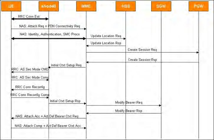
Protocol Signaling Procedures in LTE | Radisys White Paper                               4

Random Access Procedure—
System Access
The UE can utilize the services of the network once
it is synchronized in both the downlink as well as the
uplink direction. After the PLMN and Cell selection,
the UE is synchronized with the network in the
downlink direction and now it needs to synchronize
with the network in the Uplink direction. The Random
Access Procedure (RAP) over PRACH is performed by
the UE for this purpose; RAP is characterized as one
procedure independent of cell size and is common
for both FDD & TDD. There are two types of RAPs:
contention-based and non-contention-based.                  Figure 6. Contention-Based Random Access Procedure

Contention-based
Random Access Procedure
In this mode, multiple UEs may attempt to access
the network at the same time, thereby resulting
in collisions. The contention is resolved among the
contending UEs in the following 4-step process
(Figure 6):
• Step 1: Random Access Preamble on RACH
  in uplink
	Preambles are grouped based on the size of the
  L3 message the, UE would like to transmit; this           Figure 7. Non-Contention-Based Random Access Procedure
  provides an indication of resource requirements
  for the UE to the network.
                                                            Non-Contention-Based
• Step 2: Random Access Response generated                  Random Access Procedure
  by MAC on DL-SCH                                          The network initiates this procedure in case of a
	This is an indication to the UE that the eNode B          handover of a UE from one eNodeB to another in order
  received its Preamble and conveys the resources           to keep handover latency under control. It usually
  reserved for this UE.                                     reserves a set of RACH preambles for this purpose
                                                            and will transmit one from that group to the UE. There
• Step 3: First scheduled UL transmission on UL-SCH
                                                            are no collisions with other UEs because the eNodeB
	The UE sends the RRC Connection Request using
                                                            controls the procedure, which is shown in Figure 7.
  the resources given by the eNodeB in Step 2. In the
  RRC Connection request message, the UE sends              Once the UE receives the assigned RA Preamble, it
  its identifier to the network and it is used by the       sends it to the eNodeB which responds back. Steps
  eNodeB to resolve the contention in the next step.        3 and 4 given in the contention-based RAP are not
                                                            required here.
• Step 4: Contention Resolution on DL
	The eNodeB echoes back the received UE identifier
  to resolve the contention, and at this point the
  UE which has received its ID continues with the
  transmission while others will back off and try again.
Protocol Signaling Procedures in LTE | Radisys White Paper         5

RRC Connection and Initial
Attach Procedure
After the Random Access procedure, if the UE is not
already attached to the network it has to do so by
initiating the attach procedure. Otherwise, the UE
initiates the tracking area update if it changed its
tracking area since the last update. For initiating
any NAS procedure, the UE is required to establish
an RRC connection with the eNodeB. The purpose
of this procedure, depicted in Figure 8, is to request
                                                             Figure 8. RRC Connection Setup
the resources from the network for its service needs.

RRC connection establishment involves Signaling Radio
Bearer 1 (SRB1) establishment. The procedure is also
used to transfer the initial NAS message from the UE
to the MME via the eNodeB, the latter of which does
not interpret the NAS message.

NAS Attach Procedure
To get NAS-level services (for example, internet
connectivity) from the network, NAS nodes in the
network have to know about the UE. To facilitate
this; the UE has to initiate the Attach Procedure,
which is mandatory for the UE at power on and
also during the initial access of the network.

Once the attach procedure succeeds, a context is
established for the UE in the MME, and a default
bearer is established between the UE and the PDN
GW and an IP address is allocated to it. Now that the        Figure 9. Attach Procedure
UE has IP connectivity, it can start using IP-based
internet services or IMS services if the IMS network
is available and if the UE has a subscription for the
same. The NAS Attach procedure is depicted in the
Figure 9 and the steps are given below:
1. UE establishes the RRC Connection with the eNodeB.

2. The UE sends the ATTACH REQUEST message
   together with a PDN CONNECTIVITY REQUEST for
   the PDN (IP) connectivity on the established RRC
   Connection. As part of this, the eNodeB establishes
   the S1 logical connection with the MME for this UE.

3. If the Network is not able to identify the UE with
   the Identity given in the Attach Request message, it      Figure 10. NAS Common Procedures
   initiates the identification followed by Authentication
   and Security Mode procedures as given in Figure 10.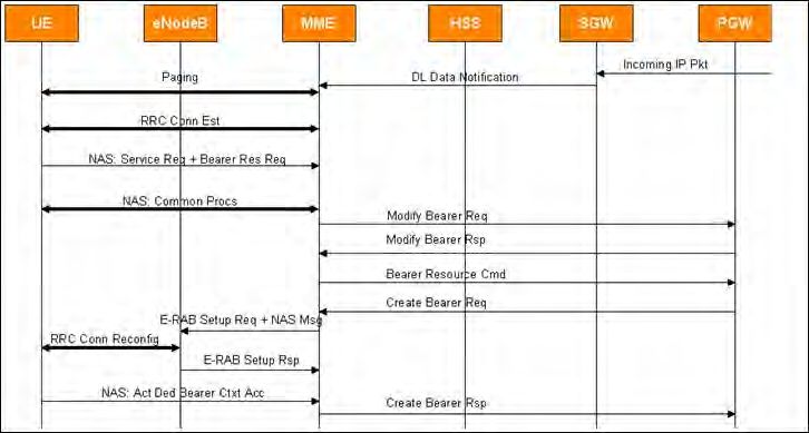
Protocol Signaling Procedures in LTE | Radisys White Paper                                  6

4. The MME update the HSS with the location of the          13. T
                                                                  he UE updates its RRC Connection configuration
   UE using the Update Location request message                  and responds back with an RRC Connection
   using the Diameter protocol; it also requests the             Reconfig Complete.
   subscriber profile from the HSS using this message.
                                                             14. T
                                                                  he eNodeB now sends the Initial Context Setup
5. The HSS updates its database with the current                Response to the MME.
   location of the UE and sends the subscriber profile
   information to the MME in the Diameter Update             15. T
                                                                  he MME sends the eGTP-C Modify Bearer
   Location Acknowledge message.                                 Request to the SGW to update the eNB Tunnel Id
                                                                 for the default bearer.
6. The MME now establishes an eGTP User Tunnel to
   establish the default bearer at the SGW; it sends a       16. A
                                                                  fter updating the information, the SGW responds
   Create Session Request (eGTP-C protocol) toward               with a Modify Bearer Response to the MME.
   the SGW.                                                  17. T
                                                                  he MME now sends the Attach Accept and
7. The SGW creates the default bearer for this UE and           Activate Default Bearer Context Request NAS
   requests the PGW to create a bearer for this UE               message to the UE.
   between the SGW and the PGW to provide end-to-            18. If the MME has allocated a GUTI while sending the
   end bearer connectivity. The PDN-GW then creates              Attach Accept, the UE needs to process it and give
   the bearer and allocates an IP Address for the UE.            back the Attach Complete as a response to it. The
8. Once the SGW receives the response from the                  UE piggy-backs the Activate Default EPS bearer
   PGW, it responds with a Create Session Response               context Accept NAS message to the MME.
   to MME.
                                                             NAS Common Procedures
9. The MME now has to establish the bearer between          The MME can initiate the NAS common procedures
   the eNodeB and SGW. It sends the S1AP Initial             during the initial Attach, Tracking Area Update and
   Context Setup Request to the eNodeB to create             other dedicated NAS procedures. These procedures,
   a context for this UE, which includes the bearer          depicted in Figure 10, are used to identify and
   Context and the security Context.                         authenticate the UE.

10. After receiving the Initial Context Setup Request,      1. T
                                                                 he MME sends the identity Request to the UE if
    the eNodeB now establishes the security                     it is unable to retrieve the UE profile from the HSS.
    parameters with the UE by initiating the AS
    Security Mode Command Procedure.                         2. T
                                                                 he UE responds back with its IMSI in the Identity
                                                                Response message to MME.
11. The UE establishes the security parameters
    (parameters required for ciphering the Integrity         3. After getting the valid IMSI from the UE, the network
    protection) and sends the Security Mode Complete            now authenticates the UE to ascertain whether the
    Message to the eNodeB. From now on, all the                 UE is genuine or not. The network and UE share a
    messages exchanged between the UE and eNodeB                secret key (the Authentication Centre stores it in the
    on the radio interface are ciphered as well as              network and the SIM card stores it in UE). Using this
    integrity-protected.                                        secret key and a random number, the network (AuC)
                                                                computes a result and expects the UE to give back
12. The eNodeB reconfigures the resources to the UE            the same result as part of this procedure.
    by sending an RRC Connection Reconfig Request to
    the UE. In this message, the eNodeB piggy-backs          4. A
                                                                 fter receiving the parameters (RAND and A
    the Activate Default EPS Bearer Context Request             UTN from the network), the UE computes the
    NAS message to the UE.                                      result and gives it back to the network in the
                                                                Authentication Response.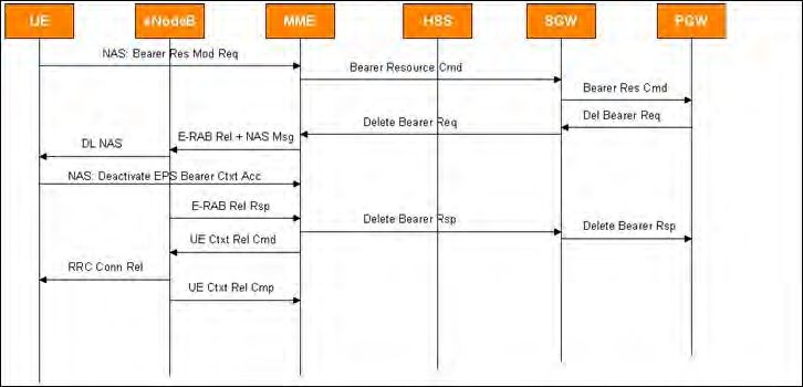
Protocol Signaling Procedures in LTE | Radisys White Paper                               7

5. After successful authentication, the network
   initiates the Security mode command to encrypt
   the NAS messages between the UE and MME;
   this is to protect the privacy of the subscriber.

6. The UE agrees to the Security mode command and
   sends the response back to the Network. After this
   step, both the UE and the network will encrypt the
   NAS messages while sending and decrypt them while
   receiving. Similarly, NAS messages are integrity-
   protected from now onwards.

UE Initiated Detach Procedure                                Figure 11. UE Initiated Detach

If the UE does not require services from the network,
it needs to deregister itself with the network by
initiating the detach procedure. One example for
this is when the UE is switched off.

This detach procedure is initiated by the UE by
sending a DETACH REQUEST message. The Detach
type IE included in the message indicates whether
detach is due to a “switch off” or not.
                                                             Figure 12. Tracking Area Update without Authentication
The network and the UE deactivate the EPS bearer
context(s) for this UE locally without peer-to-peer
signaling between the UE and MME. If the detach
type is a “switch off” then the MME does not send the
Detach Accept, otherwise it does send it to UE. While
processing the Detach from the UE, the MME initiates
the release of the EPS bearers in the network and it
also clears the UE Context held at the eNodeB (not
shown in Figure 11).

Tracking Area Update
                                                             Figure 13. Tracking Area Update with Authentication
After a successful attach to the network, the UE can
roam freely in the current Tracking Area. If it detects a
different tracking area, it needs to update the network      During the tracking area updating procedure, the MME
with this new tracking area. Similarly, the network can      may initiate an authentication procedure and setup a
request the UE to update its tracking area periodically,     security context. The Tracking Area Update Procedure
which helps the network in quickly locating the UE           without the Authentication step is given in Figure 12,
whenever a mobile-terminated call is received by the         and the steps With Authentication and Security mode
network for this UE since it can just page the UE in the     command (NAS Common Procedures) included are
last reported area.                                          given in Figure 13.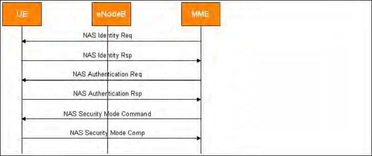
Protocol Signaling Procedures in LTE | Radisys White Paper                              8

Mobile-Originated Data Call
After successfully attaching to the network, the UE
can request the services from the Network using the
service request procedure. One example scenario is
when the UE requests resources from the Network to
initiate a data call; the UE can utilize the NAS service
request procedure for this purpose. Another example
of this procedure is to invoke MO/MT CS fallback
procedures if they are supported by the network;
the signaling messages involved in this procedure
are given in Figure 14.
1. The UE establishes the RRC Connection with
   the eNodeB.
                                                             Figure 14. Mobile-Originated Data Call
2. The UE sends the Service Request to the MME and
   requests (dedicated) bearer resources by including
   the Bearer Resource Allocation Req. As part of this,      9. T
                                                                 he PGW responds with a Create Bearer Request
   the eNodeB establishes the S1 logical connection             toward the SGW after allocating the dedicated
   with the MME for this UE. Note that the UE may also          bearer resource (TFT initialization, etc).
   send the Bearer Resource Allocation Req to the MME        10. T
                                                                  he SGW process the Create Bearer Request
   as a standalone message at a later point in time too.         and forwards to the MME for further processing.
3. At this point the network can initiate an optional       11. The MME now sends the E-RAB Setup Req to the
   identification followed by Authentication and                 eNodeB to allocate the bearer between the eNodeB
   Security Mode procedures as given in Figure 10.               and the SGW; it piggy-backs the NAS Activate
4. After the completion of the Authentication and               Dedicated EPS Bearer Context Req to the UE.
   Security Mode control procedures, the MME                 12. T
                                                                  he eNodeB allocates the resources for the Radio
   initiates the activation of default bearer with the           Bearers using an RRC Conn Reconfig Req message
   SGW / PGW by initiating the eGTP-C Modify Bearer              to the UE. The eNodeB includes the received NAS
   Req message toward the SGW.                                   message in it.
5. After receiving the Modify Bearer Req, the SGW           13. T
                                                                  he UE establishes the Radio bearers and
   activates the required resources and forwards                 responds back with an RRC Connection
   the Modify Bearer Req toward the PDN GW.                      Reconfiguration Complete Msg to the eNodeB.
6. The PGW processes the Modify Bearer Req and              14. R
                                                                  adio Bearers are established between the
   activates required resources. Note that the IP                eNodeB and the UE by now, so the eNodeB sends
   Address is allocated during the Attach procedure,             the E-RAB Setup response to the MME.
   so it will not happen now. It responds back with
   the Modify Bearer Response to the SGW and the             15. T
                                                                  he UE now sends the Activate Dedicated EPS
   SGW forwards it to the MME.                                   Bearer Context Accept NAS message to the
                                                                 MME via the eNodeB.
7. The MME now initiates the Dedicated Bearer
   establishment by sending the eGTP-C Bearer                16. T
                                                                  he MME sends a Create Bearer Response to the
   Resource Command to the SGW.                                  SGW to complete the Dedicated Bearer Activation.
                                                                 The SGW forwards it to the PGW.
8. The SGW process the Bearer Resource Command
   and forwards it to the PGW.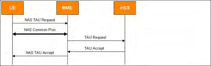
Protocol Signaling Procedures in LTE | Radisys White Paper                                 9

Mobile-Initiated Data
Call Termination
Once the UE finishes the Data call it can trigger
the release of the dedicated bearers by sending
the Bearer Resource Modification Req message
to the MME, which can then take care of releasing
the dedicated bearer with the SGW and PGW.

1. The UE triggers the dedicated bearer release
   by sending the Bearer Resource Modification
   Request to the MME.

2. The MME initiates an EPS bearer context                  Figure 15. Mobile-Initiated Data Call Release
   deactivation procedure by sending the eGTP-C
   Bearer Resource Command Msg to the SGW.

3. The SGW process the Bearer Resource Command
   and forwards it to the PGW.

4. The PGW initiates the Delete Bearer Req msg
   toward the SGW/MME to clear the requested bearer
   resources. The SGW forwards the same to the MME.

5. The MME initiates the E-RAB Release Command to
   the eNB to clear the bearer resources. It includes
   the NAS Msg: Deactivate EPS Bearer Context Req
   message for the UE.
                                                             Figure 16. Paging Procedure
6. The UE receives the NAS message from the eNB
   in the DL NAS procedure. It clears the bearer             12. T
                                                                  he eNodeB sends the UE Context Release
   resources and sends a Deactivate EPS Bearer                   complete message to the MME.
   Context Accept to the MME.

7. The eNB now sends the E-RAB Release Response
                                                             Paging
   to the MME.                                               The paging procedure is used by the network to
                                                             request the establishment of a NAS signaling
8. The MME sends the Delete Bearer Response to              connection to the UE. If there is an IP packet that
   the SGW and the SGW forwards it to the PGW                comes for a UE from the external network to the PGW
   after clearing the bearer resources.                      and if there is no dedicated bearer existing for the UE,
                                                             it will forward the IP packet to the SGW on the default
9. The PGW clears the requested Bearer resources.           bearer. Once the packet has reached the SGW on the
10. If it is the release of the last dedicated bearer       default bearer, the SGW detects the need to create
    for this UE, the MME shall release the Context           a dedicated bearer and sends the Downlink Data
    associated with this UE by sending an S1AP UE            Notification message to the MME in order the page
    Context Release Command.                                 the UE and create the dedicated bearers.

11. The eNodeB clears the Radio resources allocated         Now the MME has to ensure that the UE establishes
    to this UE by sending the RRC Connection Release         an RRC connection, so the MME sends a Paging
    message to the UE.                                       Request message to all eNodeBs associated with
                                                             the last known Tracking Area.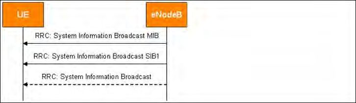
Protocol Signaling Procedures in LTE | Radisys White Paper                                10

Figure 17. Mobile Terminated Data Call

Mobile-Terminated Data Call                                   5. T
                                                                  he UE sends the Service Request to the MME and
                                                                 includes the Bearer Resource Allocation Request
For a UE-terminated call, the network sends the                  to request the Dedicated Bearer Establishment.
paging request to all the eNodeBs associated with the
last known tracking area as discussed above. When             6. F
                                                                  rom this point onward, the message sequence is
receiving the Paging Request message from the MME,               the same as that outlined in the Mobile Originated
the eNodeB sends the paging message over the radio               Data Call. Please refer to Figure 14 and its message
interface in the cells which are contained within one            sequence explanation.
of the tracking areas provided in that message.

The UE is normally paged using its S-TMSI or IMSI.
                                                              Conclusion
The Paging message also contains a UE identity                Existing 3G networks are not able to cope up with
index value in order for the eNodeB to calculate the          the rate of increasing demand for more and more
paging occasions at which the UE listens for paging           bandwidth, which has led to development of new
message. The procedure is depicted in Figure 17               technology to satisfy subscribers’ bandwidth needs.
and explained below:                                          With over 100Mbps downlink and 50Mbps uplink
                                                              (in the first phase), LTE promises to deliver high
1. The PGW/SGW receive the incoming IP packet                bandwidth on the move.
   addressed to a UE.
                                                              In this paper we covered the various signaling
2. The SGW sends a DL Data Notification to the               procedures executed by the UE and the network
   MME requesting dedicated UE bearer creation.               elements in LTE to provide services to the UE. All
3. The MME now sends a Paging message to notify              of these procedures were explained in the context of
   the UE about the incoming IP Packet.                       end-to-end signaling and the interactions of various
                                                              network elements.
4. Once the UE receives the Paging message on the
   radio interface, it establishes the RRC Connection
   with the eNodeB.
Protocol Signaling Procedures in LTE | Radisys White Paper 11
References
1
3GPP TS 36.300: “Evolved Universal Terrestrial Radio
Access (E-UTRA), Evolved Universal Terrestrial Radio
Access Network (E-UTRAN); Overall Description;
Stage 2”
2
3GPP TS 24.301: “Non-Access-Stratum (NAS)
protocol for Evolved Packet System; Stage 3”
3
3GPP TS 24.302: “Access to the 3GPP Evolved Packet
Core (EPC) via Non-3GPP Access Networks”
4
3 GPP TS 36.331: “Evolved Universal Terrestrial Radio
Access (E-UTRAN); Radio Resource Control (RRC)
Protocol Specification”
5
3GPP TS 36.401: “Evolved Universal Terrestrial
Radio Access Network (E-UTRAN); Architecture
Description”
6
3GPP TS 36.413: “Evolved Universal Terrestrial Radio
Access Network (E-UTRAN); S1 Application Protocol
(S1AP)”
7
3GPP TS 29.274: “Evolved General Packet Radio
Service (GPRS) Tunneling Control Protocol for Control
Plane (GTPv2-C) Stage 3”
Corporate Headquarters
5435 NE Dawson Creek Drive
Hillsboro, OR 97124 USA
503-615-1100 | Fax 503-615-1121
Toll-Free: 800-950-0044
www.radisys.com | info@radisys.com
©2011 Radisys Corporation.
Radisys, Trillium, Continuous Computing and Convedia
are registered trademarks of Radisys Corporation.
*All other trademarks are the properties of their respective owners.
September 2011You can also read