Enhancement of Stabilization Control in Remote Robot System with Force Feedback
←
→
Page content transcription
If your browser does not render page correctly, please read the page content below
Int. J. Communications, Network and System Sciences, 2019, 12, 99-111
                                                                                                  http://www.scirp.org/journal/ijcns
                                                                                                            ISSN Online: 1913-3723
                                                                                                              ISSN Print: 1913-3715

Enhancement of Stabilization Control in
Remote Robot System with Force Feedback

Pingguo Huang1, Takanori Miyoshi2, Yutaka Ishibashi3
1
 Seijoh University, Tokai, Japan
2
 Nagaoka University of Technology, Nagaoka, Japan
3
 Nagoya Institute of Technology, Nagoya, Japan

How to cite this paper: Huang, P.G.,            Abstract
Miyoshi, T. and Ishibashi, Y. (2019) En-
hancement of Stabilization Control in Re-       In this paper, we deal with a remote robot system in which a user can operate
mote Robot System with Force Feedback.          an industrial robot with a force sensor at a remote location by using a haptic
Int. J. Communications, Network and Sys-        interface device. We apply a method using the wave filter together with the
tem Sciences, 12, 99-111.
https://doi.org/10.4236/ijcns.2019.127008
                                                phase control filter which was previously proposed by the authors to the re-
                                                mote robot system for stabilization control. We also propose a method to en-
Received: May 27, 2019                          hance the haptic quality. By experiment, we demonstrate the effectiveness of
Accepted: July 15, 2019
                                                the proposed method. We compare the proposed method with the conven-
Published: July 18, 2019
                                                tional method quantitatively and clarify which domains the proposed method
Copyright © 2019 by author(s) and               is applied to more effectively.
Scientific Research Publishing Inc.
This work is licensed under the Creative        Keywords
Commons Attribution International
License (CC BY 4.0).                            Remote Robot System, Stabilization Control, Force Feedback, Quality, Experiment
http://creativecommons.org/licenses/by/4.0/
                Open Access

                                              1. Introduction
                                              Recently, a number of researchers focus on studies of remote robot systems with
                                              force feedback [1] [2] [3]. By using force feedback, since users can touch remote
                                              objects and feel the shape, weight, and softness of the objects, the efficiency and
                                              accuracy are expected to be largely improved [4]. However, when the haptic
                                              information such as position and/or force information is transmitted over a
                                              Quality of Sevice (QoS) [5] non-guaranteed network like the Internet, QoS may
                                              seriously deteriorate [3] [4]. Furthermore, in the remote robot systems, when the
                                              network delay increases, the reaction force becomes larger, and unstability
                                              phenomena such as vibrations of the robot and device may occur [6] [7] [8]. To
                                              solve the problems, we need to carry out stabilization control and QoS control
                                              together [4].

DOI: 10.4236/ijcns.2019.127008       Jul. 18, 2019                 99           Int. J. Communications, Network and System Sciences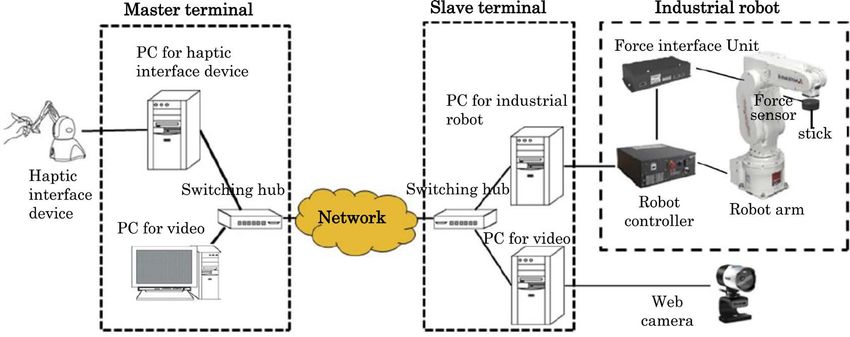
P. G. Huang et al.
There are many studies which focus on remote roboot systems with force
feedback [9] [10]. In [9], the authors asssess the Quality of Experience (QoE)
[11] about the operability of a haptic interface device for work in which a user
operates an industrial robot with a force sensor at a remote location by using the
haptic interface device while watching video. They investigate the influence of
network delay on the operability and the effect of the adaptive reaction force
control [12]. As a result, the control is effective for the remote robot system with
force feedback. In [10], Banthia et al. make a prototype telerobotic system for
live transmission line maintenance. In the system, a user can operate a haptic
interface device at a local terminal to control a remote robot arm. Then, the user
tries to do the maintenance by controlling the remote robot arm. They also
invetigate the difference in force feedback control (unilateral or bilateral control)
by experiment. However, in the papers, they do not carry out stabilization
control for the remote robot systems with force feedback. On the otherhand,
Miyoshi et al. propose stabilization control which uses the wave filter together
with the phase control filter for a haptic telecontrol system in which 1-DoF
haptic interface devices are employed in [13] and [14].
In this paper, we mainly focus on the stabilization control. In a preliminaly
experiment, we applied out the wave filter together with the phase control filter
to the remote robot system with force feedback for stabilization control, and in-
vestigated the effect of the stabilization control. In order to clarify the effect of
the conventional stabilization control, we pushed a soft object (rubber ball). As a
result, we found that the control is effective [7]. However, we found that the
control is less effective for hard objects. Therefore, we propose a method in
which we incorporate a phase lead compensation filter and a phase lag compen-
sation filter with the conventional control in [7] to achieve stabilization and en-
hance the haptic quality and investigate the effect of the proposed method and
clarify the effective domains by comparing the proposed method with the con-
ventional method. This paper has the following two main contributions: 1) we
propose an enhancement method of stabilization control to improve the haptic
quality; 2) we also clarify which domains the proposed method and conventional
method are applied to more effectively.
The remainder of this paper is organized as follows. Section 2 describes the
remote robot system with force feedback. Section 3 introduces the conventional
stabilization control and the proposed method. Section 4 explains assessment
methods, and assessment results are presented in Section 5. Finally, Section 6
concludes the paper.
2. Remote Robot System with Force Feedback
2.1. System Configuration
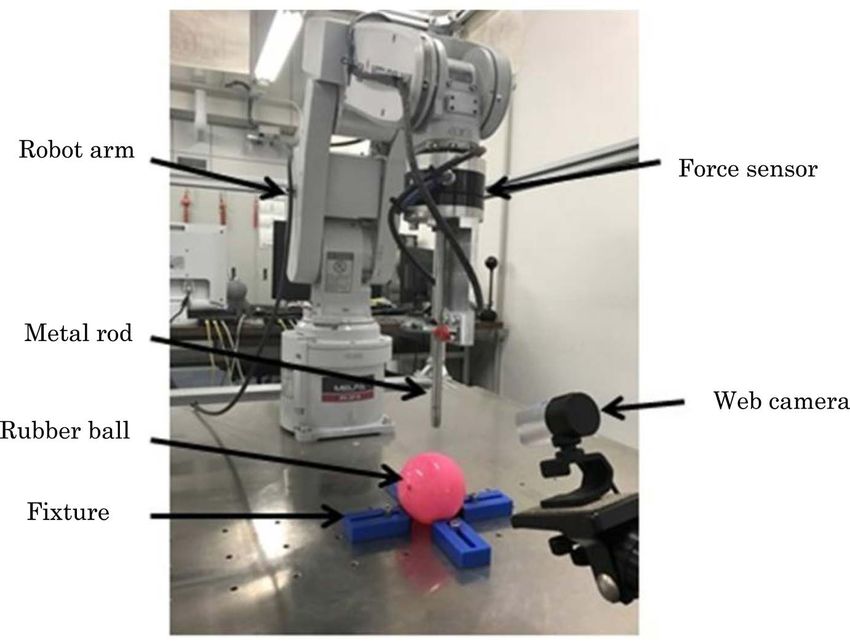
The configuration of the remote robot system with force feedback is shown in
Figure 1. The system consists of two terminals called the master terminal and
slave terminal. Each of the terminals consists of two PCs, and the PCs are connected
DOI: 10.4236/ijcns.2019.127008 100 Int. J. Communications, Network and System Sciences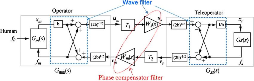
P. G. Huang et al.

                   Figure 1. Configuration of remote robot control system with haptics.

                                        to each other via a switching hub.
                                           At the master terminal, a haptic interface device (Geomagic Touch [15]) is
                                        connected to PC for haptic interface device, and another PC is used for video. At
                                        the slave terminal, one of the two PCs is used for web camera (produced by Mi-
                                        crosoft Corp., and video resolution is 1920 × 1080 pixels), and the other PC is
                                        used for industrial robot. The industrial robot consists of a robot arm (RV-2F-D
                                        by Mitsubisi Electric Corp. [16]), a robot controller (CR750-Q [16]), and a force
                                        sensor (1F-FS001-W200 [17]). The force sensor is attached to the surface of the
                                        flange of the robot arm. The force sensor is connected to the robot controller via
                                        the force interface unit. In order to investigate the effect of the proposed me-
                                        thod, we handle objects (balls) with different types of softness in this paper.

                                        2.2. Remote Operation
                                        A user at the master terminal can operate the industrial robot at the slave ter-
                                        minal by using the haptic interface device while watching video (coding scheme:
                                        Motion JPEG, average bit rate: 4.5 Mbps). The default position of the haptic in-
                                        terface device is set to the origin, and the position corresponds to the default po-
                                        sition of the industrial robot [9].
                                           The master terminal updates the position information, calculates the reaction
                                        force, and outputs the reaction force every millisecond. The master terminal also
                                        transmits the position information to the slave terminal by User Datagram Pro-
                                        tocol (UDP). At the slave terminal, the command information which is based on
                                        the position information received from the master terminal is sent to the indus-
                                        trial robot every 3.5 milliseconds by the real-time control function [18]. The
                                        force information is also acquired by the real-time control function, and the in-
                                        formation is transmitted to the master terminal by UDP.
                                          The reaction force Ft ( ) applied to the haptic interface device at time t
                                                                  m

                                        ( t ≥ 1 ) is calculated as follows:

                                                                                Ft (
                                                                                       m)
                                                                                            = K scale Ft (−1)
                                                                                                           s

                                        where Ft (−1) denotes the force receviced from the slave terminal, and K scale is a
                                                     s

DOI: 10.4236/ijcns.2019.127008                                   101            Int. J. Communications, Network and System Sciences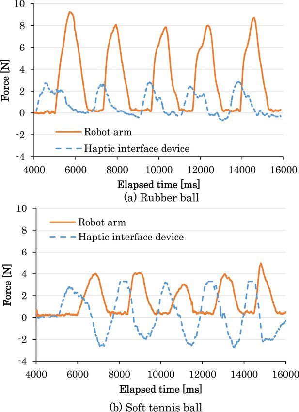
P. G. Huang et al.
force scale which is set to 1 in this paper. Furthermore, since the maximum ex-
ertable force applied to the haptic interface device is 3.3 N, the reaction force is
set to 3.3 N when the calculated force is larger than 3.3 N.
The position vector St of the industrial robot outputted at the time t ( t ≥ 2 )
is calculated as follows:
M t −1 , ( if M t −1 − M t − 2 ≤ Vmax )
St = Vmax
M M t −1 , ( otherwise )
t −1
where M t −1 is the position vector of haptic interface device received from the
master terminal, and Vmax is the maximum movement velocity. That is, in or-
der to operate the robot arm safely, the maximum movement velocity is limited
to Vmax ( Vmax = 5 mm/s in this paper).
3. Stabilization Control
3.1. Conventional Method
In bilateral control systems, unstability phenomena occur more easily as the
network delay increases [6]. The reason is as follows: The master terminal calcu-
lates reaction force by using the force information received from the slave ter-
minal, and updates the position based on the reaction force. The updated posi-
tion is transmitted to the slave terminal and the slave terminal updates its posi-
tion based on the position received from the master terminal. This means that
there exists a mechanical closed loop. The phase delay of the loop increases
when there exist network delays, and if the phase delay is larger than 180 deg,
the system becomes unstable. This is an unpreventable problem when we use a
network.
Therefore, one of solutions for the problem is to carry out stabilization control
using the wave filter together with the phase control filter [6] which was pre-
viously proposed by the authors. The block diagram of the control is shown in
Figure 2. In Figure 2, Gm(s) is the transfer function of the master terminal, and
Gs(s) is that of the slave terminal; fs is the force information which is transmitted
to the mater terminal from the slave terminal, and fm is the output force for the
master terminal; xm is the position vector obtained at the master terminal, and xr
Figure 2. Block diagram of stabilization control.
DOI: 10.4236/ijcns.2019.127008 102 Int. J. Communications, Network and System Sciences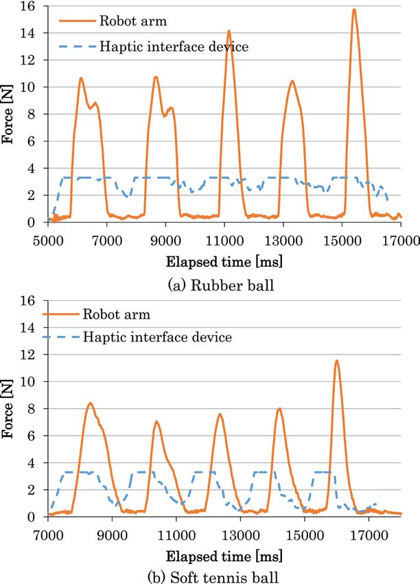
P. G. Huang et al.

                                 is the position vector for the slave terminal; fh is the force exerted from the user
                                 at the master terminal.
                                   The wave filter includes the cross part and the coefficient b. The phase control
                                 filter includes Ws(s) and Wm(s). For further details, the reader is referred to [9]
                                 and [13].

                                 3.2. Enhancement Method
                                 In a preliminary experiment, when we apply the conventional method to the
                                 remote robot system in the three axes, unstability phenomena (vibrations of the
                                 robot and device) occured when users tried to push a hard object such as a
                                 tennis ball.
                                   In order to solve the problem, we propose an enhancement method in which
                                                                                   1 0.25s + 1
                                 we incorporate a phase lead compensation filter ( ×           ) to Gm(s) and a
                                                                                   2 0.08s + 1
                                                                1 0.05s + 1
                                 phase lag compensation filter ( ×          ) to Gs(s). The former filter is used
                                                                2 0.25s + 1
                                 to solve the phase lag caused by the second order integration from the force to
                                 position. In order to avoid unstability due to the useless time of the industrial
                                 robot, the later filter is employed to lower the gain in high frequency ranges.
                                                                                     1
                                 Furthermore, Ws(s) and Wm(s) are set to                      , and b at the master
                                                                               ( 0.03s + 1)
                                                                                            2

                                 terminal is set to 0.3 and that at slave terminal is set to 0.6 (this means that the
                                 mapping ratio [6] from the work space of the haptic interface device to that of
                                 the industrial robot is 2:1).

                                 4. Assessment Method
                                 In our experiment, we employ a network emulator (NIST Net [19]) instead of
                                 the network of Figure 1. A metal rod is fixed at the tip of the force sensor which
                                 is attached to the surface of the flange of the robot arm. Four fixtures are setting
                                 on the top of rack which is used to fix the industrial robot arm to fix objects as
                                 shown in Figure 3. We generate a constant delay (called the additional delay in
                                 this paper) for each packet transmitted between the master and slave terminals.
                                 We handle two types of work (work 1 and work 2) to investigate the effect of
                                 proposed method. In work 1, each subject is asked to push a ball by operating
                                 the robot arm while watching video, and in work 2, the subject pushes a ball by
                                 operating the robot arm and identify what kind of the ball is pushed according
                                 to the softness without watching video. In the two types of work, the subject
                                 pushes the ball by the metal rod fixed at the robot arm.
                                   In work 1, the subject pushes a ball from above and return back after pushing
                                 the ball for about 4 seconds, and he/she repeats the work three times (the subject
                                 is also asked to push the ball from the obliquely upward and the side, since the
                                 results are almost the same as those from above, we show only the results when
                                 the subjects push the ball from above). Because the effects of the conventional

DOI: 10.4236/ijcns.2019.127008                         103        Int. J. Communications, Network and System Sciences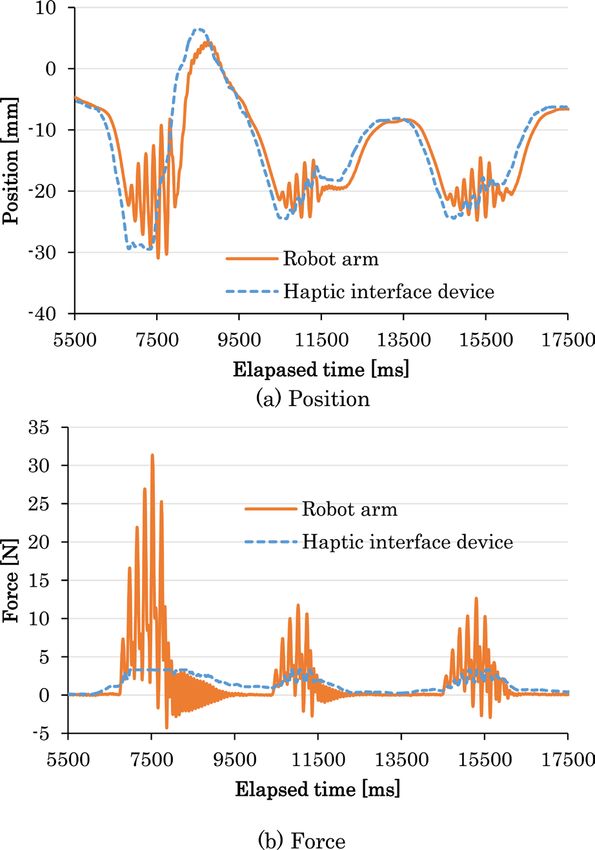
P. G. Huang et al.

                                 Figure 3. Appearance of robot arm.

                                 method for soft objects have been confirmed, we here deal with only a tennis
                                 ball, which is used as a hard object in the work. In order to compare the pro-
                                 posed method with the conventional method, we carry out the assessment by
                                 changing the constant delay as follows: 0 ms, 100 ms, 200 ms, 400 ms, and 800
                                 ms. We measure the position of the haptic interface device, the position of the
                                 industrial robot, the output force of the haptic interface device, and the force
                                 obtained from the force sensor of the robot arm.
                                   In work 2, we handle two balls with different softness as in [18]; one is a rub-
                                 ber ball (diameter: 70 mm), and the other is a soft tennis ball (diameter: 65 mm).
                                 Each subject pushes a ball from above and identifies the ball only by the softness
                                 he/she perceived. Therefore, we do not use the camera and the PCs for video in
                                 Figure 1. Furthermore, the robot arm is set to move only in vertical direction
                                 (the y axis) so that all the subjects can do the work under the same condition
                                 [20]. Also, we use papers with thickness of 5 mm under the soft tennis ball so
                                 that the height of the two balls is the same.
                                   Before the experiment, each subject practices to push the two balls to confirm
                                 the softness about 1 minute without any additional delay. In the practice, the
                                 type of ball is told to the subject, and then he/she tries to push a ball from above
                                 five times for each ball.
                                   In the experiment, the subject pushed a ball as in the practice to identify the
                                 ball only by perceived softness without telling what the ball is. Each ball was se-
                                 lected 5 times, and the order was random for each subject. We carried out the
                                 experiment by setting the constant delay to 0 ms, 50 ms, 100 ms, 200 ms, and
                                 300 ms, and obtained the average of correct answer rate. The number of subjects
                                 (males) whose ages were between 21 to 25 is 15.

DOI: 10.4236/ijcns.2019.127008                           104          Int. J. Communications, Network and System Sciences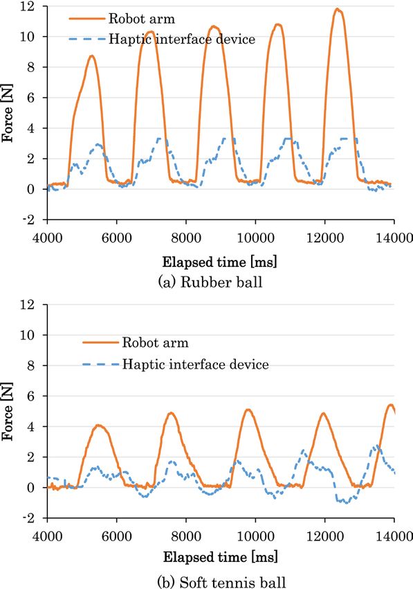
P. G. Huang et al.

                                 5. Assessment Results
                                 5.1. Work 1 (Push Ball) (3 Axes)
                                 Experiment results of work to push a ball (tennis ball) are shown in Figure 4
                                 through Figure 6. The results of the conventional method are shown in Figure
                                 4, and those of the proposed method are shown in Figure 5. Since the system
                                 with the conventional method becomes unstable, we show only the results of the
                                 proposed method when the additional delay is 800 ms in Figure 6. Also, because
                                 the results in the x and z axes are almost the same as those in the y axis, we
                                 demonstrate only the results in the y axis.
                                    From Figure 4, we see that the instability phenomena (vibrations) occur when
                                 the subject tries to push the ball. This means that the system is instable. From
                                 Figure 5, we find that there are almost no vibrations; we can say that the system
                                 is stable. However, the position of the haptic interface device is twice as that of
                                 the industrial robot. This is because the coefficient b is set as described in 3.2.
                                    From Figure 6, we can also notice that the system is stable as that in Figure 5.
                                 However, the position of the haptic interface device is delayed, and the delay is
                                 proportional to the network delay [8].
                                    Furthermore, we carried out the experiment by using a soft tennis ball and a
                                 rubber ball, and we found that the stability can be attained by both conventional
                                 method and proposed method.

                                 Figure 4. Position and force in conventional method (y axis, additional delay: 0 ms).

DOI: 10.4236/ijcns.2019.127008                            105             Int. J. Communications, Network and System Sciences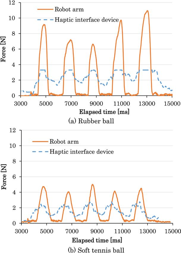
P. G. Huang et al.

                                  Figure 5. Position and force in proposed method (y axis, additional delay: 0 ms).

                                 Figure 6. Position and force in proposed method (y axis, additional delay: 800 ms).

DOI: 10.4236/ijcns.2019.127008                   106            Int. J. Communications, Network and System Sciences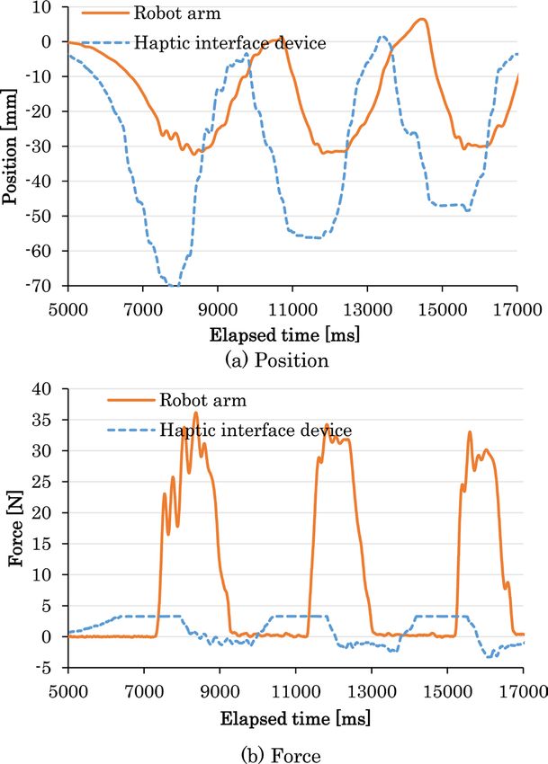
P. G. Huang et al.

                                 5.2. Work 2 (Ball Identification) (1 Axis)
                                 The average of correct answer rate versus the additional delay is shown in Fig-
                                 ure 7. We also plot the 95% confidence intervals in the figure.
                                   From Figure 7, we notice that the average of correct answer rate of the pro-
                                 posed method is better than that of the conventional method. In order to clarify
                                 the reasons, we compare the force of the haptic interface device and that of the
                                 robot arm in the proposed method with those in the conventional method. The
                                 results are shown in Figure 8 through Figure 11. From Figure 8 and Figure 9,

                                      Figure 7. Average of correct answer rate versus additional delay.

                                                Figure 8. Force in conventional method (additional delay: 0 ms).

DOI: 10.4236/ijcns.2019.127008                          107            Int. J. Communications, Network and System Sciences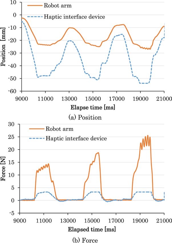
P. G. Huang et al.

                                    Figure 9. Force in proposed method (additional delay: 0 ms).

                                 Figure 10. Force in conventional method (additional delay: 200 ms).

DOI: 10.4236/ijcns.2019.127008            108            Int. J. Communications, Network and System Sciences
P. G. Huang et al.
Figure 11. Force in proposed method (additional delay: 200 ms).
when the additional delay is 0 ms, we can see similar tendencies between the
conventional method and the proposed method. Since the force of the haptic in-
terface device and that of the robot arm are very different when the object is the
rubber ball or the soft tennis ball, it is easy to identify the ball by the perceived
softness, and the average of correct answer rate is almost 100%. From Figure 10
and Figure 11, we find that the force of the haptic interface device and that of
the robot arm are very different from each other when the balls are different in
the proposed method. Therefore, the average of correct answer rate of the pro-
posed method is higher than that of the conventional method. However, from
Figure 10 and Figure 11, we see that when the object is the rubber ball, the force
of the haptic interface device is more close to the real feeling of pushing the ball
in the proposed method. However, when the object is the soft tennis ball, the
force of the haptic interface device in the proposed method is more close to the
real feeling of pushing the ball in the conventional method. In the proposed me-
thod, the subject felt larger reaction force which is opposite to the movement di-
rection always, and it is difficult for the subject to perceive the softness of the
ball.
From above discussion, we can say that the proposed method is more suitable
for objects with certain hardness, and the conventional method has much better
effects when the objects are not so hard.
DOI: 10.4236/ijcns.2019.127008 109 Int. J. Communications, Network and System SciencesP. G. Huang et al.
6. Conclusions
In this paper, we applied stabilization control using the wave filter together with
the phase control filter which was previously proposed by the authors to the re-
mote robot system with force feedback and proposed a method to enhance hap-
tic quality. We carried out the experiment to investigate the effect of the pro-
posed method and compare the effect with that of the conventional method. As
a result, the proposed method is more suitable for objects with certain hardness,
and the conventional method has much better effects when the objects are not so
hard.
As the next step of our research, we need to clarify the effective domain by
carrying out other types of work such as writing characters. It is also important
to study QoS control and stabilization control together in multiple remote robot
systems with force feedback.
Acknowledgements
The authors thank Yuichi Toyota and Eijirou Taguchi at Nagoya Institute of
Technology for their support of the experiment. This work was supported by
JSPS KAKENHI Grant Number 18K11261.
Conflicts of Interest
The authors declare no conflicts of interest regarding the publication of this pa-
per.
References
[1] Ohnishi, K. (2013) Real World Haptics: Its Principle and Future Prospects. The
Journal of the Institute of Electrical Engineers of Japan, 133, 268-269. (In Japanese)
https://doi.org/10.1541/ieejjournal.133.268
[2] Kawai, T. (2013) Haptics for Surgery. The Journal of the Institute of Electrical En-
gineers of Japan, 133, 282-285. https://doi.org/10.1541/ieejjournal.133.282
[3] Ishibashi, Y. and Huang, P. (2016) Improvement of QoS in Haptic Communication
and Its Future. The IEICE Transactions on Communications, J99-B, 911-925. (Jap-
anese Edition)
[4] Huang, P. and Ishibashi, Y. (2013) QoS Control and QoE Assessment in Mul-
ti-Sensory Communications with Haptics. The IEICE Transactions on Communica-
tions, E96-B, 392-403. https://doi.org/10.1587/transcom.E96.B.392
[5] ITU-T Rec. I. 350 (1993) General Aspects of Quality of Service and Network Per-
formance in Digital Networks.
[6] Miyoshi, T., Maeda, Y., Morita, Y., Ishibashi, Y. and Terashima, K. (2014) Devel-
opment of Haptic Network Game Based on Multi-Lateral Tele-Control Theory and
Influence of Network Delay on QoE. Transactions of the Virtual Reality Society of
Japan, Special Issues on Haptic Contents, 19, 559-569. (In Japanese)
[7] Huang, P., Miyoshi, T. and Ishibashi, Y. (2017) Stability Control in Remote Bilateral
Robot Control System with Force Feedback. IEEE the 3rd International Conference
on Control, Automation and Robotics, Nagoya, 22-24 April 2017.
[8] Huang, P., Miyoshi, T. and Ishibashi, Y. (2017) Stabilization of Bilateral Control in
DOI: 10.4236/ijcns.2019.127008 110 Int. J. Communications, Network and System SciencesP. G. Huang et al.
Remote Robot System. IEICE Technical Report, CQ2016-125. (In Japanese)
[9] Suzuki, K., Maeda, Y., Ishibashi, Y. and Fukushima, N. (2015) Improvement of
Operability in Remote Robot Control with Force Feedback. 4th Global Conference
on Consumer Electronics, Osaka, 27-30 October 2015, 16-20.
https://doi.org/10.1109/GCCE.2015.7398509
[10] Banthia, V., Maddahi, Y., Zareinia, K., Liao, S., Olson, T., Fung, W., Balakrishnan,
S. and Sepehri, N. (2017) A Prototype Telerobotic Platform for Live Transmission
Line Maintenance: Review of Design and Development. Transactions of the Insti-
tute of Measurement and Control, 40, 3273-3292.
https://doi.org/10.1177/0142331216687021
[11] ITU-T Rec. G. 100/P. 10 Amendment 1 (2007) New Appendix I: Definition of Qual-
ity of Experience (QoE).
[12] Matsunaga, K., Ishibashi, Y., Fukushima, N. and Sugawara, S. (2012) Effect of
Adaptive Reaction Force Control in Remote Control System with Haptic Media and
Video. The 27th International Technical Conference on Circuits/Systems, Comput-
ers and Communications, Sapporo, 15-18 July 2002.
[13] Miyoshi, T., Terasima, K. and Buss, M. (2006) A Design Method of Wave Filter for
Stabilizing Non-Passive Operating System. IEEE Conference on Computer Aided
Control System Design, 2006 IEEE International Conference on Control Applica-
tions, 2006 IEEE International Symposium on Intelligent Control, Munich, 4-6 Oc-
tober 2006, 1318-1324. https://doi.org/10.1109/CCA.2006.286029
[14] Duong, M.D., Miyoshi, T., Terashima, K. and Rodriguezseda, E.J. (2008) Analysis
and Design of Position-Force Teleoperation with Scattering Matrix. 17th IFAC
World Congress, Seoul, 6-11 July 2008, 12715-12720.
https://doi.org/10.3182/20080706-5-KR-1001.02151
[15] http://www.geomagic.com/en/products/phantom-omni/overview
[16] http://www.mitsubishielectric.co.jp/fa/products/rbt/robot/lineup/manual/f/bfp-a88
99k.pdf (In Japanese)
[17] http://dl.mitsubishielectric.co.jp/dl/fa/members/document/manual/robot/bfp-a8940
/bfp-a8940Z.pdf (In Japanese)
[18] http://dl.mitsubishielectric.co.jp/dl/fa/members/document/manual/robot/bfp-a8080
/bfp-a8080e.pdf (In Japanese)
[19] Carson, M. and Santay, D. (2003) NIST Net—A Linux-Based Network Emulation
Tool. ACM SIGCOMM Computer Communication Review, 33, 111-126.
https://doi.org/10.1145/956993.957007
[20] Taguchi, E., Ishibashi, Y. and Huang, P. (2017) Experiment on Softness Identifica-
tion of Objects in Remote Robot System with Haptics: Effect of Stabilization Con-
trol. IEICE Technical Report, CQ2017-38. (In Japanese)
DOI: 10.4236/ijcns.2019.127008 111 Int. J. Communications, Network and System SciencesYou can also read