Development of a Climbing Robot with Vacuum Attachment Cups
←
→
Page content transcription
If your browser does not render page correctly, please read the page content below
Proceedings of International Conference On Innovations, Recent Trends And Challenges In Mechatronics,
Mechanical Engineering And New High-Tech Products Development –
MECAHITECH’11, vol. 3, year: 2011
Development of a Climbing Robot with Vacuum Attachment Cups
T.C. Apostolescu*, C. Udrea**, D. Duminica**, G. Ionascu**, L. Bogatu**, Laurenţiu Adrian Cartal**
*“Titu Maiorescu” University, str. Dâmbovnicului, nr. 22, 040441
Bucharest, Romania, E-mail: apostolescucatalin@yahoo.com
**Mechatronics and Precision Mechanics Department, "Politehnica" University of Bucharest,
Spl. Independentei 313, 060042 Bucharest, Romania
Abstract
The problem of a wall-climbing robot is holding on the wall. There are many factors, which effect in
holding, all forces, robot movement and mechanical design. In this paper an autonomous mobile robot, which
moves on horizontal and vertical surfaces using an electro-pneumatically vacuum cups attachment system is
presented. The original robot construction, developed as a cleaning robot, includes two triangular platforms that
provide a light weight. The system modelling and simulation were performed by means of SolidWorks – Cosmos
Motion software package. The robot driving is ensured by a comand system developed using LabView software
facilities.
Keywords
Mechatronics concept, climbing robot, cleaning, vacuum fixing, electro-pneumatic actuation.
Introduction
By its nature, the theoretical and experimental research in the field of robotics has an interdisciplinary
character specific to the mechatronics concept through which mechanics, electronics and informatics are
sinergically integrated.
Wall-climbing robots are helpful systems for various applications on vertical surfaces. Wall cleaning for
buildings is one of the areas which is expected to obtain a strong benefit from these robots. The most common
attachment principle is the vacuum adhesion [1]-[3], where the robot carries an onboard pump to create a
vacuum inside the cups, which are pressed against the wall. This system enables the robots to adhere on any type
of material, with low energy consumption. The vacuum adhesion is suitable for usage on smooth surfaces,
because the roughness can influence a leakage loss in the vacuum chamber such as suction cup.
The mobile robots endowed with platforms and legs with cups are widely spread in practical
applications due to high relative forces of locomotion, mobility and good suspension. The disadvantage of
increased overall size less disturbs in applications of cleaning and inspection of large vitrified surfaces covering
the buildings [4].
A new generation of cleaning robots based on all-pneumatic technology is on study [5].
The objective of this research was to develop a robot of small sizes and reduced weight for window
cleaning. The novelty of the approach consists of the robot capability to move on vertical surfaces, which
involves basic studies enlarging the horizon of knowledge related to: displacement cinematic structures, robot
leg anchoring solutions, actuating solutions, as well as control system of such robots.
Climbing robot construction
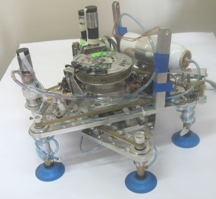
The autonomous robot, which is the subject of a vast research work [6], is shown in two positions in
Figure 1: robot placed on a horizontal surface (a) and robot placed on a vertical surface (b).
As shown, the fixing system consists of six suction cups, three for each of the two triangular platforms
through which the cinematic operating scheme ensures horizontal or vertical movement of the robot.
Platform 5, that is the nearest to the support surface, will be referred to as the interior platform and the
other platform 2 will be the exterior platform. For the interior platform are used the suction cups 4 and for the
exterior platform - suction cups 1.
Other components are the followings: motor-reduction gear 3 for controlling linear motion of the
platforms, electro valves 6 and 11 for controlling vacuum in suction cups, vacuum micro pump 7, motor-
reduction gear 8 for controlling rotation motion of the platforms, motor-reduction gear 9 for controlling motion
of suction cups of the interior platform, motor-reduction gear 10 for controlling motion of suction cups of the
258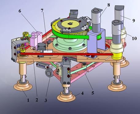
Proceedings of International Conference On Innovations, Recent Trends And Challenges In Mechatronics,
                    Mechanical Engineering And New High-Tech Products Development –
                                    MECAHITECH’11, vol. 3, year: 2011

exterior platform.

                                                          a)

                      2

                     5

                                                                            11

                                                          b)
                                     Figure 1: 3D Model of the robot placed on
                                    horizontal surface (a) and vertical surface (b)

          To obtain an autonomous robot, the electric actuation of all degrees of freedom was chosen, as well as
for the depressurization of the cups. An original driving system was introduced for the moving of robot legs. The
system uses screw mechanisms synchronized by a toothed belt transmission. The developed system for the
relative translation of the platforms contains a ball guide way of reduced size and good guiding accuracy. The
use of a rack mechanism allows a compact and fast actuation. The rotation of the robot is achieved by modifying
                                                         259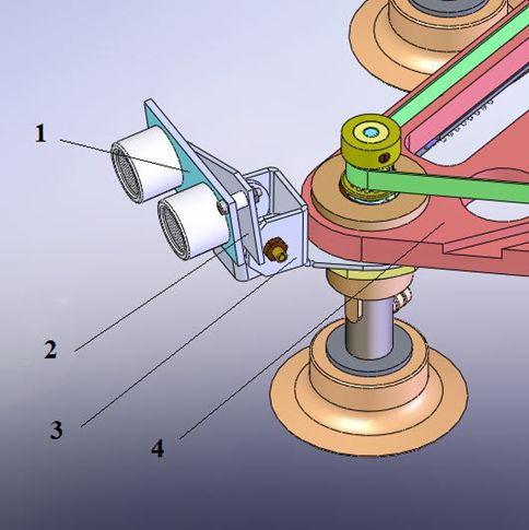
Proceedings of International Conference On Innovations, Recent Trends And Challenges In Mechatronics,
                    Mechanical Engineering And New High-Tech Products Development –
                                    MECAHITECH’11, vol. 3, year: 2011

the relative angular position of the two platforms.
          The cinematic scheme of the robot is presented in Figure 2: 1, 9 - vacuum cups; 2, 8 - screw
mechanisms; 3 - exterior platform (PLE); 4, 6 - toothed driving belts; 5 - shaft; 7 - interior platform (PLI); 10 –
guiding part; 11 - rolling guide way; 13 - rack; 14 - gear; M1R1, M2R2, M3R3, M4R4 - motor-reduction gears; m1 -
raising and lowering of PLI legs; m2 - raising and lowering of PLE legs; m3 - orienting rotation; m4 - translation
between platforms.

                                         Figure 2: Cinematic scheme of robot

         The pneumatic diagram used for reducing the pressure inside the cups of the robot legs, in order to
ensure the contact force when vacuumed suction cups adhere on the surface to be cleaned, is presented in Figure
3: PV - vacuum micro pump (NMP 015 B – KNF Neuberger); Ac - tank; EM1, EM2 - electromagnets for the
electro valve operating; V1, V2, V3 - suction cups for the interior platform; V4, V5, V6 - suction cups for the
exterior platform; D - depression; A - atmospheric pressure.
                                                     A
                                                                    Ac

                                     M                   PV

                                                D    A                        D   A
                                      EM1                           EM2

                                           v1       v2   v3              v4       v5   v6

                                            Figure 3: Pneumatic diagram

          Although the robot attaches itself to the glass surface vacuum suction cups, a significant miniaturization
was achieved. The overall sizes of the robot, 350 x 350 x 220 mm, prove that degree of miniaturization is
optimal, also presenting a high quality of autonomous movement.
          The main parameters of the robot (Figure 4) are:
•    triangular platform side length L = 247 mm, corresponding to a stroke S of about 100…110 mm;
•    full cycle for a translation step: 200…220 mm;
•    maximum angle of relative rotation between platforms: 30º;
•    duration of a cycle: 8s;
•    depression Δp = 0.57 bar;
•    diameter of the vacuum cups (ESS 50 – FESTO type): 50 mm;
•    normal detachment force: 86 N;
•    lateral detachment force: 110 N;
        • cup raising and lowering speed: approx. 6mm/s.
                                                              260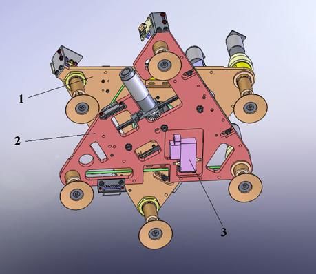
Proceedings of International Conference On Innovations, Recent Trends And Challenges In Mechatronics,
                    Mechanical Engineering And New High-Tech Products Development –
                                    MECAHITECH’11, vol. 3, year: 2011

                  Figure 4: Photo of the autonomous mobile robot used for cleaning operations

Cup behavior under external force

         An important part of the research concerned with the robot fixing on the vacuum cups. In order to
establish their bearing capacity, the cups were subjected to external (normal, lateral and combined) loads. Tests
were performed for different depressions. The influence of the different supporting (cleaned) materials was also
studied, as well as the behaviour of the cup in presence of different liquids on the surface.
         Force determinations with Δp = 0.57 bar using the pump NMP 015 B from the robot were performed,
Figure 5. The results are useful for supporting simulation on the robot legs. The characteristic in this case, for
glass surfaces, is shown in Figure 6.
         Regarding the force determinations on wet surfaces, the characteristic shape is maintaining, but with
some differences of the values. The cup behaviour at wetting with water diminishes a little the performance,
because water is eliminated during the connection on the surface, in the contact zone of the cup. An enhanced
reduction of the force can be observed at wetting with detergent, which persists partially after connecting.
         The maximum detachment force values for the conditions from above, at different depressions, are
given in Figure 7. A more substantial reduction of cup capacity, only for wetting with detergent (of about 6 %),
was found.

                                  Figure 5: Cup characteristic for Δp = 0.57 bar

                                                      261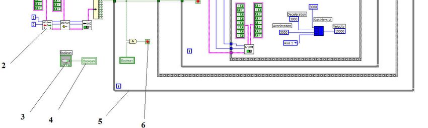
Proceedings of International Conference On Innovations, Recent Trends And Challenges In Mechatronics,
                    Mechanical Engineering And New High-Tech Products Development –
                                    MECAHITECH’11, vol. 3, year: 2011

                  Figure 6: Cup behaviour on glass for different conditions: FSt06 – dry surface,

           FstUd06 – wet surface with water, FstDet – wet surface with detergent for window washing

               Figure7: Cup detachment force from glass for different conditions: Fd – dry surface,

             FdUd – wet surface with water, FdDet – wet surface with detergent for window washing

Modelling and simulation of the robot displacement relative to the cups

          As the robot functions are in a sequential mode, the simulations can be performed separately for
translations and rotations [7]. Simulations are obtained with Cosmos Motion program attached to SolidWorks
software. The robot displacement relative to the cups is the displacement of one platform related to the other
platform on whose cups the robot fixing was made. The simulation results are similar for both PLE and PLI
because the movable masses are similar. A parabolic variation was imposed for the acceleration. The numerical
values for simulation are the followings: nM max = 4280 rot/min (maximum rotation speed of the motor), vmax = 5
mm/s (maximum translation speed), amax = 20 mm /s2 (maximum acceleration), tac = 0,19 s (acceleration time),
treg = 1,22 s (displacement time with constant speed), and ttot = 2 tac + treg = 1,6 s (periodic time of the full
movement). Figures 8, 9, and 10 present the simulation results for acceleration, velocity, and displacement. From
Figure 10, the stroke ΔS = 20 mm was checked.
          The variation of the instantaneous power during the robot translation relative to the cups results from
Figure 11. The maximum value of the instantaneous power can be consequently computed: Ptr c = 0.56 W.
Considering the losses at the motor level, the necessary power at the exit of the driving motor was determined as
equal to PM tr c = 4.49 W. This is ensured by that one of 6.5 W of the chosen motor. The results of all simulations
                                                       262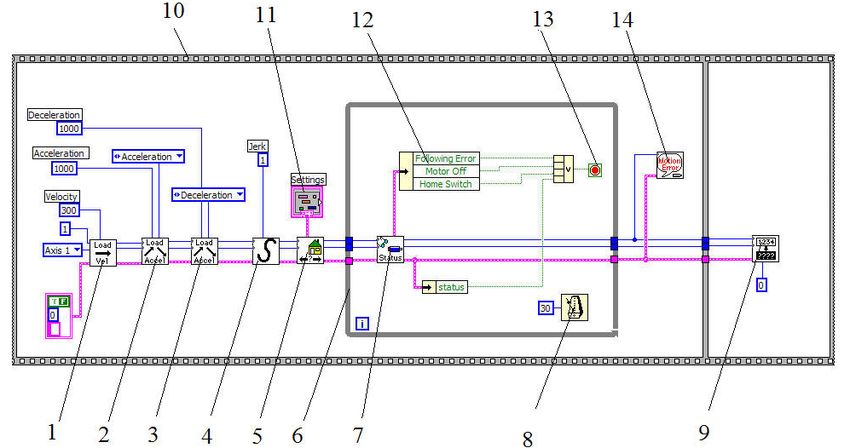
Proceedings of International Conference On Innovations, Recent Trends And Challenges In Mechatronics,
                   Mechanical Engineering And New High-Tech Products Development –
                                   MECAHITECH’11, vol. 3, year: 2011

have been used in dimensioning and choosing of the driving motor-reduction gears M1R1 … M4R4 (MAXON
type). They were validated by experimental data, performed on the actual experimental model of autonomous
mobile robot.

                Figure 8.:Acceleration variation during the robot translation relative to the cups

                  Figure 9: Velocity variation during the robot translation relative to the cups

               Figure 10: Displacement variation during the robot translation relative to the cups

                                                      263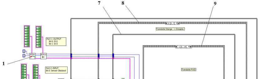
Proceedings of International Conference On Innovations, Recent Trends And Challenges In Mechatronics,
                    Mechanical Engineering And New High-Tech Products Development –
                                    MECAHITECH’11, vol. 3, year: 2011

             Figure 11: Instantaneous power variation during the robot translation relative to the cups

Control of the robot

         The robot can be controlled with a data acquisition board 7344 National Instruments and LabView
programming or with microcontrollers. The microcontroller BS2 (Parallax) is used, easy to program but with a
number of limitations concerning the control of motor speeds.
         Using a data acquisition board allows introducing home switches for each of four servo axes in order to
find the reference position. For axis 1 (robot translation) and axis 4 (orienting rotation), home switches are
mounted between the limiting micro switches. For axes 2 and 3, representing cup translations for PLE and PLI,
respectively, micro switches are used only as stroke limit. The reference position is found with the help of a
photoelectric system, as shown in Figure 12. The system consists of a light stop 6 fixed on the mobile plate 4
whose displacement s gives the position of the cups. The light stop moves between the sides of the photoelectric
sensor 2 (of type OPB 916).

    Figure 12: Photoelectric system used in order to establish the reference position of axes 2 and 3. 1 – corner support;
      2 – photoelectric sensor; 3 – rod for movement obstruction; 4 – plate attached to the mobile rod; 5 – mobile rod;
                                               6 – light stop; 7 – microswitch.

        Figure 13 presents the scheme of the photoelectric system used to determine the reference position.
When the light stop reaches the optical axis of the sensor, the state of its output changes. The emitter diode is
supplied through the resistor Ra for current limitation. A power amplifier OPB916 is connected at the circuit
                                                            264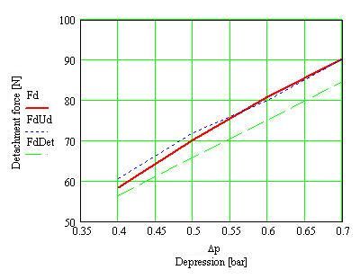
Proceedings of International Conference On Innovations, Recent Trends And Challenges In Mechatronics,
                    Mechanical Engineering And New High-Tech Products Development –
                                    MECAHITECH’11, vol. 3, year: 2011

output. The suppressor diode Ds protects the transistor during its disconnection. Connection to the data
acquisition board is made through the NO contact of the relay Rel.

                                         Figure 13: Scheme of the photoelectric circuit

         The LabVIEW software program that allows founding the home switch is shown in Figure 14. The
activation of limit switches is also needed during the search. After the reference is found, the position counter is
reset. The program is applied for each of four axes of the acquisition board.

        Figure 14: LabVIEW program for founding the home switch: 1 – maximum speed load; 2 – acceleration load;
     3 – deceleration load; 4 – elements of curve S (kinematics without jerk); 5 –home switch use; 6 –while type cycle;
    7 – reading of search state; 8 – delay producing; 9 – position counter reset; 10 – sequential cycle with two sequences;
   11 – search settings; 12 – reading of different interrupt situations; 13 –end cycle condition; possible errors indication of
                                                          possible errors

         The programs consists of two sequences introduced by the cycle 10. The first one searches the reference
position and the second resets the position counter (subVI 9).
         The subVI 1 loads the maximum search speed and performs axis selection. The subVIs 2 and 3 load the
maximum acceleration and deceleration. The subVI 4 defines the movement kinematics (S curve of the speed).
A while type cycle is introduced. The subVI 7 reads the state of the search. The subVI 12 seizes various
interruption cases. The subVI 13 stops the cycle.
         In order to clean glass surfaces, the robot must cover the whole window area, paying especial attention
to corners. The main control program of the robot controls the travel on the vitrified surface by horizontal and
vertical movements, as well as by rotations that allow changing the direction. An ultrasonic PING sensor
(Parallax) was introduced as decision element for changing the direction and stopping. The sensor is mounted on
the PLI platform using the corner 3 and the jointed holder 2, as shown in Figure 15.
                                                              265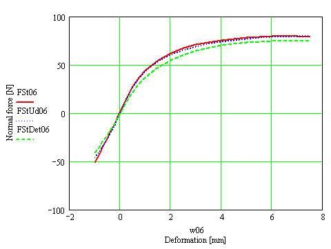
Proceedings of International Conference On Innovations, Recent Trends And Challenges In Mechatronics,
                    Mechanical Engineering And New High-Tech Products Development –
                                    MECAHITECH’11, vol. 3, year: 2011

        Figure 15: The ultrasonic sensor mounted on the interior platform: 1 – sensor; 2 – sensor holder; 3 – corner;
                                          4 – interior platform PLI of the robot

         Figure 16 presents a sequential cycle of travel. The cycle consists of the following sequences:
         0. sequential translation from left to right. This sequence ends at the appearance of the signal (given by
the sensor S) of proximity of the rim from right side;
         1. clockwise rotation with 90º;
         2. lowering with a step;
         3. clockwise rotation with 90º;
         4. sequential translation from right to left. This sequence ends at the appearance of the signal (given by
the sensor) of proximity of the rim from left side;
         5. counterclockwise rotation with 90º;
         6. lowering with a step;
         7. counterclockwise rotation with 90º.

                                            Figure 16: Travel cycle of the robot

         The robot covers the whole window area by repeating the travel cycle. The robot stops if the sensor S
sends the signal of proximity of the bottom rim of the vitrified surface.

                                                            266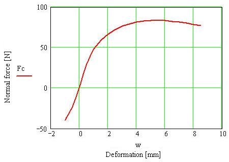
Proceedings of International Conference On Innovations, Recent Trends And Challenges In Mechatronics,
                    Mechanical Engineering And New High-Tech Products Development –
                                    MECAHITECH’11, vol. 3, year: 2011

        The block diagram of the program is shown in Figure 17.

   Figure 17: Block diagram of main control program of the robot: 1 - setting port 1 as output; 2 - setting port 2 as input;
     3 - initialization of local variable; 4 - boolean local variable; 5 – while cycle of the travel program; 6 – travel stop;
           7 – first order while cycles; 8 – sequences of the first order cycles; 9 – sequences of the first order cycles

         The program uses the ports 1 and 2 of the acquisition board. The port 1 is used as program output,
sending the commands towards the electro valves. The port 2 is used as input, receiving the signal from the
sensor S. The control 3 initializes the boolean local variable as “False”. The variable changes its state to “True”
during vertical displacement. The signal from the sensor S is used also for stopping the horizontal translation
sequences.

Conclusions

         Some aspects regarding design and control of a prototype of climbing autonomous robot with vacuum
attachment cups, for cleaning operations on vitrified surfaces, are presented. An optimal degree of
miniaturization, and at the same time, a high quality of autonomous movement is ensured. The modelling and
simulation of the robot functioning certifies that its performances are comparable to similar solutions conceived
worldwide.

References
[1] F. Cepolina, R. Michelini, R. Razzol and M. Zoppi, “Gecko, a Climbing Robot for Wall Cleaning”, 1 st Int.
Workshop on Advances in service Robotics ASER03, March 13-15, Bardolino, Italia, 2003,
http://www.dimec.unige.it/PMAR/
[2] T. Miyake, H. Ishihara and M. Yoshimura, “Basic Studies on Wet Adhesion System for Wall Climbing
Robots”, in Proceedings of the 2007 IEEE/RSJ International Conference on Intelligent Robots and Systems, San
Diego, CA, USA, Oct.29-Nov.2, 2007, pp. 1920-1925.
[3] Fr. Novotny and M. Horak, “Computer Modelling of Suction Cups Used for Window Cleaning Robot and
Automatic Handling of Glass Sheets”, in MM Science Journal, June, 2009, pp. 113-116.
[4] D. Sun, J. Zhu and S. K. Tso, “A climbing robot for cleaning glass surface with motion planning and visual
sensing, Climbing & walking robots towards new applications”, Hao Xiang Zhang (ed.), I Tech Education and
Publishing, Vienna, Austria, 2007, pp.546.
[5] G. Belforte, G. Mattiazzo and R. Grassi, “Innovative solution for climbing and cleaning on smooth surfaces”,
Proceedings of the 6th JFPS International Symposium on Fluid Power, Tsukuba, Japan, 2005, pp. 251-255.
[6] T.C. Apostolescu, “Autonomous robot with vertical displacement and vacuummetric attachment system” (in
Romanian), Ph.D. Thesis, POLITEHNICA University of Bucharest, Romania, 2010.
[7] N. Alexandrescu, T.C.Apostolescu, C. Udrea, D. Duminica, and L.A. Cartal, “Autonomous mobile robot
with displacement in a vertical plane and applications in cleaning services”, Proceedings of IEEE International
Conference on Automation, Quality and Testing, Robotics (AQTR 2010_R-S1-6 2923), Cluj-Napoca, Romania.

                                                              267
You can also read