Installation, Operation, Inspection and Maintenance Manual - Kelso ...
←
→
Page content transcription
If your browser does not render page correctly, please read the page content below
Installation, Operation, Inspection
        and Maintenance Manual

ANGLE VALVE MODELS:
K2AV – Kelso 2” Angle Valve Series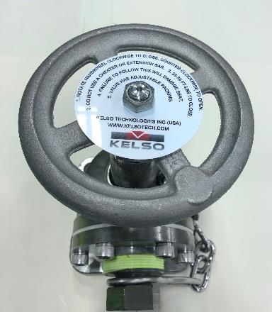
1
                                                                                                                    K2AV SERIES ANGLE VALVE

                                               Table of Contents
1.0               Introduction                                                                                                                                   2
      1.1. Precautions                                                                                                                                           2
      1.2. Regulations                                                                                                                                           2
      1.3. Technical Specifications                                                                                                                              3
      1.4. Required Tools                                                                                                                                        4

2.0               Valve Installation                                                                                                                             5
       2.1 Preliminary Considerations                                                                                                                            5
       2.2 Installation Procedure                                                                                                                                5
       2.3 Leak Inspection                                                                                                                                       6
       2.4 Valve Operation                                                                                                                                       6

3.0               Disassembly                                                                                                                                    7
       3.1 Procedure                                                                                                                                             7

4.0               Inspection                                                                                                                                    13
       4.1 Components                                                                                                                                           13
       4.2 Cleaning                                                                                                                                             14

5.0               Assembly                                                                                                                                      15
       5.1 Procedure                                                                                                                                            15

6.0               Pressure Testing and Final Assembly                                                                                                           20
       6.1 Testing Procedure                                                                                                                                    20
       6.2 Final Assembly                                                                                                                                       21

7.0               Maintenance                                                                                                                                   23

       7.1 Testing Valves in Storage                                                                                                                            23
       7.2 Valve Repair                                                                                                                                         23

8.0               Special Guidelines                                                                                                                            24

9.0               Warranty Information                                                                                                                          24

10.0              Revisions                                                                                                                                     24

                 © 2021 Kelso Technologies (USA) Inc. All Kelso Valves are Patent Protected. Detailed designs are subject to change without notice.
                                       Kelso Technologies Inc. 1526 Texas Ave, Bonham, TX 75418, Phone: (903) 583-9200
Document No. – IOIM008
Revision 2 – 6/1/2021 (Original Release 6/30/2016)                       www.kelsotech.com                                                            Printed in U.S.A.
2
                                                                                                                    K2AV SERIES ANGLE VALVE

1.0 Introduction
            Kelso Technologies is known for offering innovative products with
            safety and reliability in mind. Our K2AV Angle Valve has been
             designed and engineered to withstand the harsh commodities and
            severe environmental conditions present in rail tank car service.

               1.1 Precautions
                          The 2” Angle Valve can be used as a safety device in the storage and
                          transportation of a wide variety of fluids, many of which are hazardous and
                          could cause serious injury or damage. Only personnel which are properly
                          qualified should install, repair or rebuild the Angle Valve. Only certified
                          parts from Kelso or one of its authorized representatives should be used in
                          the Angle Valve. The Angle Valve may be installed on DOT tank cars that
                          carry hazardous chemicals and may travel under pressure.

                          Read these instructions prior to performing periodic maintenance or
                          repairs.

               1.2 Regulations
                          Kelso valves are used in contact with a variety of products,
                          many of which are hazardous. The acceptance and
                          transportation of products are regulated by DOT and AAR in the
                          U.S.A and in Canada by CTC and Transport Canada.
                          Regulations of other governmental bodies must be complied
                          with. All personnel should be familiar with and follow these
                          regulations. Nothing in these instructions is intended to conflict
                          with or supersede these regulations.

                          NOTE: Specifications are subject to change without notice.
                 © 2021 Kelso Technologies (USA) Inc. All Kelso Valves are Patent Protected. Detailed designs are subject to change without notice.
                                       Kelso Technologies Inc. 1526 Texas Ave, Bonham, TX 75418, Phone: (903) 583-9200
Document No. – IOIM008
Revision 2 – 6/1/2021 (Original Release 6/30/2016)                       www.kelsotech.com                                                            Printed in U.S.A.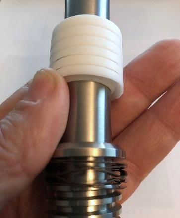
3
                                                                                                                    K2AV SERIES ANGLE VALVE

               1.3 Technical Specifications
                          1.3.1                 Figure 1.1 shows attributes of the K2AV Angle Valve. Figure 1.2
                                                shows the General Arrangement of the valve and Figure 1.3 is a
                                                general Bill of Materials for the given arrangement.

               Valve Model                             Orifice (In)                          Weight (lbs.)                         Flange
                                                                                                                                Thickness (In)
                       K2AV                                 2.125                                    30                                   0.75
                                                                                                       Figure 1.1 K2AV Series Attributes

                                                                          Figure 1.2 K2AV Series General Arrangement

                 © 2021 Kelso Technologies (USA) Inc. All Kelso Valves are Patent Protected. Detailed designs are subject to change without notice.
                                       Kelso Technologies Inc. 1526 Texas Ave, Bonham, TX 75418, Phone: (903) 583-9200
Document No. – IOIM008
Revision 2 – 6/1/2021 (Original Release 6/30/2016)                       www.kelsotech.com                                                            Printed in U.S.A.
4
                                                                                                                    K2AV SERIES ANGLE VALVE

                   ITEM NO.                              QTY.        DESCRIPTION
                      1                                    1         BODY
                      2                                    1         STEM
                      3                                    1         PACKING SCREW
                      4                                    1         SEAL DISC
                      5                                    1         SEAT
                      6                                    1         SEAL RETAINER
                      7                                    1         K2AV HANDLE
                      8                                    1         KAV OPERATION DECAL
                      9                                    1         FACE PLATE
                      10                                   1         PACKING BOTTOM WASHER
                      11                                   1         FACE PLATE GASKET
                      12                                   1         2" NPT PLUG & CHAIN
                      13                                   1         JAM NUT
                      14                                   1         SHOULDER BOLT
                      15                                   1         WAVE SPRING
                      16                                   1         O-RING
                      17                                   1         JAM NUT
                      18                                   1         HEX NUT
                      19                                   1         PACKING KIT
                      20                                   6         SOCKET HEAD CAP SCREW
                      21                                   1         KAV NAMEPLATE (NOT SHOWN)
                                                     Figure 1.3 K2AV Series General Arrangement Bill of Materials

               1.4 Required Tools and Torque Values
                          Required Tools

                            Sockets/Wrenches – ½” and ¾”
                            Adjustable Wrench                                        Lint Free Cloth
                            Hook and Pick Tool                                       400 Grit Alum. Oxide Emery Cloth
                            Ratchet                                                  Thread Locker
                            Torque Wrench                                            Anti-Seize
                            Wire Brush                                               Hey Key/Allen Wrench 3/8”

                          Torque Values

                                            Item No.                           Description                                       Torque Value
                                               14                            Seal Disc Bolt                                         8 ft.-lbs.
                                               13                          Seal Retainer Nut                                       20 ft.-lbs.
                                               18                              Handle Nut                                          30 ft.-lbs.
                                                3                            Packing Screw                                         25 ft.-lbs.
                                               17                        Packing Screw Jam Nut                                     40 ft.-lbs.
                                               20                           Face Plate Bolt                                        45 ft.-lbs.
                                               12                              Valve Plug                                        Wrench Tight

                 © 2021 Kelso Technologies (USA) Inc. All Kelso Valves are Patent Protected. Detailed designs are subject to change without notice.
                                       Kelso Technologies Inc. 1526 Texas Ave, Bonham, TX 75418, Phone: (903) 583-9200
Document No. – IOIM008
Revision 2 – 6/1/2021 (Original Release 6/30/2016)                       www.kelsotech.com                                                            Printed in U.S.A.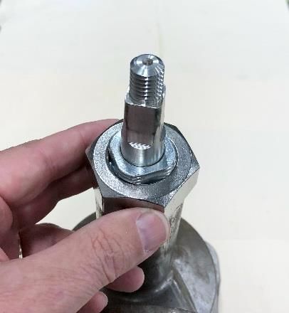
5
                                                                                                                    K2AV SERIES ANGLE VALVE

2.0 Valve Installation
                          Only companies and their personnel which are certified by the Association
                          of American Railroads shall perform maintenance and testing of Kelso
                          angle valves, pursuant to either M1002 or M1003.

               2.1 Preliminary Considerations
                          New valves are tested, adjusted and sealed at Kelso. If a new valve has
                          been left in its original packaging, is undamaged and is not more than six
                          months old, it may be installed on a tank car without retesting or
                          recalibration. If the valve has exceeded six months, it must be returned
                          for retesting and recalibration. Prior to installation, ensure that the valve
                          remains clean and that the gasket sealing surfaces are not damaged in
                          any way, shape or form.

               2.2 Installation Procedure
                              1. Prior to removing any valve or fitting from a tank, ensure
                                 that the internal pressure is atmospheric and that
                                 personnel exposure to hazardous chemicals are
                                 eliminated.
                              2. When the securement bolts have been removed from the
                                 mounting flange, remove the valve and discard the old
                                 flange gasket.
                              3. The flange mating surface should be free from gouges,
                                 scrapes, and excessive corrosion. With a tongue and
                                 groove mating surface, ensure that while removing the
                                 old gasket no damage is done to the bottom of the
                                 groove. Any burrs, radial gouges and debris should be
                                 removed.
                              4. A new valve should be kept in its original packaging to
                                 prevent damage to the valve or its components.
                              5. A test certificate should be available to verify the test
                                 date of the valve, if the last known test date was within
                                 six months, the valve can be installed without retesting or
                                 requalifying.
                              6. Place a new gasket on the tank mounting flange. Kelso
                                 Technologies does not supply the flange gasket. Gasket
                                 material should be compatible with the chemical being
                                 shipped. Inspect the valve mating flange for defects as
                                 described in Paragraph 3 above. Install the valve on the
                                 mounting flange and secure using bolts, tightening to a
                                 prescribed

                 © 2021 Kelso Technologies (USA) Inc. All Kelso Valves are Patent Protected. Detailed designs are subject to change without notice.
                                       Kelso Technologies Inc. 1526 Texas Ave, Bonham, TX 75418, Phone: (903) 583-9200
Document No. – IOIM008
Revision 2 – 6/1/2021 (Original Release 6/30/2016)                       www.kelsotech.com                                                            Printed in U.S.A.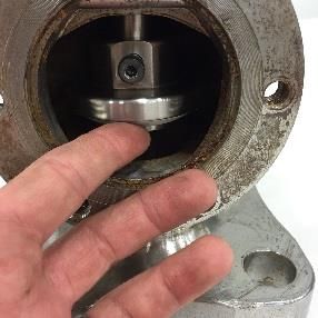
6
K2AV SERIES ANGLE VALVE
7. Torque of 200 to 250 ft.-lbs. Our suggested value is only
to be used in the event your company does not have a
procedure for this.
8. Once the angle valve has been secured to the car, a
suitable leak test should be performed to ensure the
flange mating surfaces are pressure tight.
2.3 Leak Inspection
All newly installed valves must be tested under pressure to
confirm that no leaks are present.
WARNING: Loose nuts, improper tongue seating in the
flange, damaged and wrong size gaskets can result in leaks at
the valve mating surfaces.
2.4 Valve Operation
Operation of all valves must conform to all applicable TC,
AAR, DOT (Part 173.31, 174.67, etc.) and other
governmental bodies. Follow install facilities company
policies regarding valve operation.
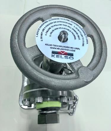
1. A handle extension or “cheater” bar should not be used
to close valve. Excessive force will shear the angle
valve’s Teflon seat, making valve inoperable or difficult
to seal. Leaking valves that will not close by normal
means (closing using hand wheel) are defective and
should be removed from service.
2. Pipe plug threads should be clean, free from corrosion
and crossed and/or worn threads. The mating threads
of the valve body should also be in proper working
condition.
3. The angle valve contains an adjustable packing gland.
The Gland is factory set and under normal
circumstances a new valve needs no adjustment. To
prevent the packing screw jam nut from backing off,
torqueing it to 40 ft.-lbs. is required. Its primary function
is to prevent the packing screw from backing out while
the stem is turning.
© 2021 Kelso Technologies (USA) Inc. All Kelso Valves are Patent Protected. Detailed designs are subject to change without notice.
Kelso Technologies Inc. 1526 Texas Ave, Bonham, TX 75418, Phone: (903) 583-9200
Document No. – IOIM008
Revision 2 – 6/1/2021 (Original Release 6/30/2016) www.kelsotech.com Printed in U.S.A.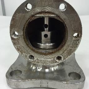
7
                                                                                                                    K2AV SERIES ANGLE VALVE

3.0 Disassembly
            Prior to any servicing of a Kelso Valve, ensure all participating
            personnel have adequate personal protective equipment.

               3.1 Procedure
                                 1. Use an adjustable wrench to remove the valve plug from the face
                                 plate of the angle valve. (Figures 3.1 & 3.2)

                                                     Figures 31. and 3.2 Valve Plug Removal

                                 2. A 3/8” Allen/hex key wrench with ratchet/socket is needed to
                                 remove the six bolts securing the face plate. Remove the face plate
                                 and the face plate gasket. (Figures 3.3 & 3.4)

                                                     Figures 3.3. and 3.4 Face Plate Removal

                 © 2021 Kelso Technologies (USA) Inc. All Kelso Valves are Patent Protected. Detailed designs are subject to change without notice.
                                       Kelso Technologies Inc. 1526 Texas Ave, Bonham, TX 75418, Phone: (903) 583-9200
Document No. – IOIM008
Revision 2 – 6/1/2021 (Original Release 6/30/2016)                       www.kelsotech.com                                                            Printed in U.S.A.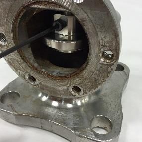
8
                                                                                                                    K2AV SERIES ANGLE VALVE

                                 3. Turn handle until the head of the seal disc bolt is visible. Loosen
                                 and remove the seal disc bolt with a 5/32” hex key wrench. Turn
                                 handle counterclockwise until the stem is free from the seal disc.
                                 (Figures 3.5, 3.6 & 3.7)

                                                                                                            Figure 3.7

                                               Figures 3.5, 3.6 and 3.7 Seal Disc Removal

                              4. Remove seal disc from angle valve. Set aside.
                              (Figure 3.8)

                                                     Figure 3.8 Seal Disc Removed

                 © 2021 Kelso Technologies (USA) Inc. All Kelso Valves are Patent Protected. Detailed designs are subject to change without notice.
                                       Kelso Technologies Inc. 1526 Texas Ave, Bonham, TX 75418, Phone: (903) 583-9200
Document No. – IOIM008
Revision 2 – 6/1/2021 (Original Release 6/30/2016)                       www.kelsotech.com                                                            Printed in U.S.A.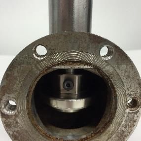
9
                                                                                                                    K2AV SERIES ANGLE VALVE

                                 5. With 3/4” wrench or socket remove handle nut and lift
                                 the handle from the stem. (Figures 3.9 & 3.10)

                                                     Figures 3.9 and 3.10 Handle Removal

                                  6. Loosen and remove the packing screw jam nut using
                                           an adjustable wrench. (Figure 3.11)

                                                        Figure 3.11 Jam Nut Removal

                 © 2021 Kelso Technologies (USA) Inc. All Kelso Valves are Patent Protected. Detailed designs are subject to change without notice.
                                       Kelso Technologies Inc. 1526 Texas Ave, Bonham, TX 75418, Phone: (903) 583-9200
Document No. – IOIM008
Revision 2 – 6/1/2021 (Original Release 6/30/2016)                       www.kelsotech.com                                                            Printed in U.S.A.
10
K2AV SERIES ANGLE VALVE
7. Loosen and remove the packing screw using an
adjustable wrench. Remove O-ring from packing screw
using a hook and pick. (Figures 3.12, 3.13 & 3.14)
Figures 3.12, 3.13 and 3.14 Packing Screw / O-Ring Removal
8. Rotate the stem counter clockwise to remove the
stem from the angle valve body. (Figure 3.15)
Figure 3.15 Valve Stem Removal
© 2021 Kelso Technologies (USA) Inc. All Kelso Valves are Patent Protected. Detailed designs are subject to change without notice.
Kelso Technologies Inc. 1526 Texas Ave, Bonham, TX 75418, Phone: (903) 583-9200
Document No. – IOIM008
Revision 2 – 6/1/2021 (Original Release 6/30/2016) www.kelsotech.com Printed in U.S.A.11
K2AV SERIES ANGLE VALVE
9. Remove packing kit, packing base ring/bottom washer
and wave spring from stem. (Figures 3.16, 3.17 & 3.18)
Figures 3.16, 3.17 and 3.18 Stem Components Removal
10. To disassemble the seal disc, first remove the seal
retainer nut with a ½” wrench. (Figure 3.19)
Figure 3.19 Disassemble Seal Disc
© 2021 Kelso Technologies (USA) Inc. All Kelso Valves are Patent Protected. Detailed designs are subject to change without notice.
Kelso Technologies Inc. 1526 Texas Ave, Bonham, TX 75418, Phone: (903) 583-9200
Document No. – IOIM008
Revision 2 – 6/1/2021 (Original Release 6/30/2016) www.kelsotech.com Printed in U.S.A.12
K2AV SERIES ANGLE VALVE
11. Lift off seal retainer. (Figure 3.20)
Figure 3.20 Seal Retainer Removal
12. Remove seal from seal disc. Use a hook and pick as
needed. (Figures 3.21 & 3.22)
Figures 3.21 and 3.22 Seal Removal
© 2021 Kelso Technologies (USA) Inc. All Kelso Valves are Patent Protected. Detailed designs are subject to change without notice.
Kelso Technologies Inc. 1526 Texas Ave, Bonham, TX 75418, Phone: (903) 583-9200
Document No. – IOIM008
Revision 2 – 6/1/2021 (Original Release 6/30/2016) www.kelsotech.com Printed in U.S.A.13
K2AV SERIES ANGLE VALVE
4.0 Inspection
The valve and most components can be visually inspected without
removal from the tank car, however, a proper inspection should be
made whenever the valve is rebuilt or when suspect operation
warrants.
4.1 Components
1. Seal - The seal must be replaced when the valve is rebuilt.
Upon inspection the seal should be secured and concentric in
the sealing disc groove. For seals with etch, install with etch
facing up, toward (against) sealing disc. The etch identifies the
current seal pedigree compound and should be validated with
the car owner specifications. If the seal is installed with etch
down (away from) the sealing disc, it will not impact form, fit or
function but it may impact the integrity of the etch. Impact of
etch is not cause for condemnation. The seal should be free
from tears, folds, abrasions, cracking and a buildup of debris.
Replace when any of these defective conditions occur.
The seal has been manufactured with a proprietary
composition and should only be replaced with Kelso supplied
material.
It is recommended that any replacement parts be purchased
through Kelso Technologies for form, fit and function.
2. Seal Disc - The seal disc seat face and the seal retainer should
be smooth and free from scratches, nicks and gouges. The seat
face should also be free from paint, dirt, rust and scale prior to
the application of the seal.
3. Valve Seat - The valve seating area within the valve body must
be free from radial cuts, rust, and corrosion. The valve seat is
most crucial for correct valve operation and any discontinuity
can cause the valve to leak.
4. Stem - The stem once removed from the valve body should
have its threads examined. Some dings and wear are allowed
as long as the parallel wrenching surfaces at the top of the
screw remains square. If the surfaces become rounded, the
stem must be replaced. The threads of the stem should be
clean and lightly lubricated. An appropriate sized thread die
can be used to correct small imperfections and a flat file can be
used to correct slightly damaged ACME threads. If cracks
and/or fractures are discovered, replace the stem. The area
© 2021 Kelso Technologies (USA) Inc. All Kelso Valves are Patent Protected. Detailed designs are subject to change without notice.
Kelso Technologies Inc. 1526 Texas Ave, Bonham, TX 75418, Phone: (903) 583-9200
Document No. – IOIM008
Revision 2 – 6/1/2021 (Original Release 6/30/2016) www.kelsotech.com Printed in U.S.A.14
K2AV SERIES ANGLE VALVE
where the packing screw contacts the body must be free from
nicks, scratches and/or dings.
5. Body - Inspect body for corrosion degradation, particularly in the
seat area. Clean seat area from corrosion, contamination, pits,
etc., that may form leak paths. Tapped holes at side flange are
7/16-14. Discard body if threads are stripped, crossed or corroded.
6. Outlet Flange - The 2” NPT flange must be in good condition,
threads should not be stripped, crossed, etc. Threads can be
cleaned using a standard 2” NPT tap. A thread gage should be
used to ensure threads are not oversized. The standard hand-
tight engagement is 0.436” for 2” thread. The acceptable
tolerance is plus or minus one thread. If tolerance is exceeded
a new part must be obtained.
7. Packing Screw - The thread should be clean and sharp
without nicks, scratches, defects, etc. that will strip of gall the
threads when screwed into the body.
8. Plug – 2” NPT plug must be in good condition, threads should
not be stripped, crossed, etc. Threads can be cleaned using a
standard 2” NPT die. A thread gage should be used to ensure
threads are not oversized. The standard hand-tight
engagement is 0.436” for 2” thread. The acceptable tolerance
is plus or minus one thread. If tolerance is exceeded a new
part must be obtained.
4.2 Cleaning
All components, excluding the Packing Kit and seal, of the
Kelso Angle Valve may be cleaned using the following:
1. Wire brushes and/or clean towel / cloth
2. Low pressure water, glass bead, sand or soda blasting
provided the blast media is not angular in form
3. A chemical / surfactant application, in conjunction with
manufactures prescribed instructions, to achieve a desired
result. It is suggested the chemical / surfactant be of neutral
pH to ensure the integrity of the metal composition
4. Regardless of cleaning method, it is suggested that the parts
be double rinsed and dried (w/ sanitary towel) prior to
reinstallation and immediately after any chemical / surfactant
application.
Disposal should be managed in accordance with all applicable
state and federal regulations.
© 2021 Kelso Technologies (USA) Inc. All Kelso Valves are Patent Protected. Detailed designs are subject to change without notice.
Kelso Technologies Inc. 1526 Texas Ave, Bonham, TX 75418, Phone: (903) 583-9200
Document No. – IOIM008
Revision 2 – 6/1/2021 (Original Release 6/30/2016) www.kelsotech.com Printed in U.S.A.15
K2AV SERIES ANGLE VALVE
5.0 Assembly
5.1 Procedure
1. Insert the seal in the seal disc and ensure that the seal is seated.
Install so that the flat portion of the seal is against the seal disc and
the bevel of the seal is away from the seal disc. (Figures 5.1 & 5.2)
Figures 5.1 and 5.2 Seal Area and Orientation
2. Install the seal retainer with the bevel facing away from the seal
disc. (Figures 5.3 & 5.4)
Figures 5.3 and 5.4 Seal Retainer and Orientation
© 2021 Kelso Technologies (USA) Inc. All Kelso Valves are Patent Protected. Detailed designs are subject to change without notice.
Kelso Technologies Inc. 1526 Texas Ave, Bonham, TX 75418, Phone: (903) 583-9200
Document No. – IOIM008
Revision 2 – 6/1/2021 (Original Release 6/30/2016) www.kelsotech.com Printed in U.S.A.16
K2AV SERIES ANGLE VALVE
3. Apply thread locker to retainer thread of seal disc and
install the seal retainer nut. Tighten and torque to 20 ft-
lb. (Figure 5.5)
Figure 5.5 Seal Retainer Installation
4. Place assembled seal disc into valve body. The seal faces down
and flat portion that accepts stem should face out through the face
of the body. (Figures 5.6 & 5.7)
Figures 5.6 and 5.7 Seal Disc in Valve Body
© 2021 Kelso Technologies (USA) Inc. All Kelso Valves are Patent Protected. Detailed designs are subject to change without notice.
Kelso Technologies Inc. 1526 Texas Ave, Bonham, TX 75418, Phone: (903) 583-9200
Document No. – IOIM008
Revision 2 – 6/1/2021 (Original Release 6/30/2016) www.kelsotech.com Printed in U.S.A.17
K2AV SERIES ANGLE VALVE
5. Apply lube to the outside diameter of the stem and the interior of
the packing kit. Then insert the wave spring, packing base
ring/bottom washer (flat side against wave spring) and packing kit
onto stem. The packing kit should interlock with the peaks fitting
into the groove, place on stem groove face first. Note: 6 spacers
are in the packing kit. Install on the square end of stem. (Figures
5.8 & 5.9)
Figures 5.8 and 5.9 Packing Kit onto Stem
6. Apply a thin coating of dry moly lube to the stem threads and thread
stem into valve body with square end of stem up, until the through
hole of the stem is centered in face of valve. (Figures 5.10 & 5.11)
Figures 5.10 and 5.11 Stem into Valve Body
© 2021 Kelso Technologies (USA) Inc. All Kelso Valves are Patent Protected. Detailed designs are subject to change without notice.
Kelso Technologies Inc. 1526 Texas Ave, Bonham, TX 75418, Phone: (903) 583-9200
Document No. – IOIM008
Revision 2 – 6/1/2021 (Original Release 6/30/2016) www.kelsotech.com Printed in U.S.A.18
K2AV SERIES ANGLE VALVE
7. Apply thread locker to seal disc bolt threads before
installation. Lift seal disc and install seal disc bolt.
Tighten to 8 ft-lbs. (Figure 5.12)
Figure 5.12 Seal Disc Installation
8. Insert O-ring into packing screw. (Figure 5.13)
Figure 5.13 O-Ring Installed into Packing Screw
9. Thread packing screw into body, square end up. Tighten
and torque to 25 ft-lbs. (Figure 5.14)
Figure 5.14 Packing Screw into Valve Body
© 2021 Kelso Technologies (USA) Inc. All Kelso Valves are Patent Protected. Detailed designs are subject to change without notice.
Kelso Technologies Inc. 1526 Texas Ave, Bonham, TX 75418, Phone: (903) 583-9200
Document No. – IOIM008
Revision 2 – 6/1/2021 (Original Release 6/30/2016) www.kelsotech.com Printed in U.S.A.19
K2AV SERIES ANGLE VALVE
10. Apply a thin layer of lube to packing screw jam nut. Then install
packing screw jam nut. While holding packing screw in place,
tighten jam nut. (Figure 5.15)
Figure 5.15 Packing Screw Installation
11. Align face plate gasket and face plate with holes on valve body.
Apply thread locker to bolt before installing onto valve body.
Tighten to 45 ft-lb. (Figures 5.16 & 5.17)
Figures 5.16 and 5.17 Face Plate Installation
NOTE: After assembly is complete, assure that the valve
plug is available, in order to proceed to testing.
© 2021 Kelso Technologies (USA) Inc. All Kelso Valves are Patent Protected. Detailed designs are subject to change without notice.
Kelso Technologies Inc. 1526 Texas Ave, Bonham, TX 75418, Phone: (903) 583-9200
Document No. – IOIM008
Revision 2 – 6/1/2021 (Original Release 6/30/2016) www.kelsotech.com Printed in U.S.A.20
K2AV SERIES ANGLE VALVE
6.0 Pressure Testing and Final Assembly
Because of the valve’s simplicity, testing is only required to check the valve
for leaks.
Refer to AAR publication “Regulations for Tank Cars”. Appendix A
applies specifically to valves. This section prescribes pressures and
their tolerances.
Test stand must have an appropriate mounting for valve. Test gauges
must meet requirements of AAR D 4.5.
If your company has its own process and procedure for assembly and
testing, follow it; otherwise this procedure offers only the essential steps
and guidelines.
6.1 Testing Procedure
1. Perform bubble leak testing in accordance with an approved
procedure.
2. Secure valve to test fixture.
3. Raise pressure on test fixture and test. If valve fails, investigate
seal and gasket mating surfaces and torque on face plate to
resolve problem. Also, check the packing gland for any leaks.
4. Remove valve from the test fixture and forward to final assembly.
© 2021 Kelso Technologies (USA) Inc. All Kelso Valves are Patent Protected. Detailed designs are subject to change without notice.
Kelso Technologies Inc. 1526 Texas Ave, Bonham, TX 75418, Phone: (903) 583-9200
Document No. – IOIM008
Revision 2 – 6/1/2021 (Original Release 6/30/2016) www.kelsotech.com Printed in U.S.A.21
K2AV SERIES ANGLE VALVE
6.2 Final Assembly
1. Remove valve plug and open valve.
2. Rinse valve to remove test solution and foreign material
from the valve assembly.
3. Dry valve by wiping with a cloth or using pressurized air.
4. Place plastic tongue protector on valve body to prevent
unintentional damage.
5. Open valve to ensure retainer is not in contact with the
valve seat. Apply preservative to valve body.
6. While holding packing screw in place, torque jam nut to 40
ft-lbs. (Figure 6.1)
Figure 6.1 Torque Packing Screw
7. Place valve plug chain ring on stem. (Figure 6.2)
Figure 6.2 Plug Chain Ring on Stem
© 2021 Kelso Technologies (USA) Inc. All Kelso Valves are Patent Protected. Detailed designs are subject to change without notice.
Kelso Technologies Inc. 1526 Texas Ave, Bonham, TX 75418, Phone: (903) 583-9200
Document No. – IOIM008
Revision 2 – 6/1/2021 (Original Release 6/30/2016) www.kelsotech.com Printed in U.S.A.22
K2AV SERIES ANGLE VALVE
8. Place handle on stem. Then place operation decal on
handle. Attachment point for handle is a tapered to fit. Add
thread locker to thread and install handle nut. Tighten to
30 ft-lbs. (Figures 6.3 & 6.4)
Figures 6.3 and 6.4 Handle Installation
9. Apply teflon tape to threads of valve plug then insert plug
into outlet flange. Engage only 2 or 3 threads. (Figure 6.5)
Figure 6.5 Valve Plug Engagement
© 2021 Kelso Technologies (USA) Inc. All Kelso Valves are Patent Protected. Detailed designs are subject to change without notice.
Kelso Technologies Inc. 1526 Texas Ave, Bonham, TX 75418, Phone: (903) 583-9200
Document No. – IOIM008
Revision 2 – 6/1/2021 (Original Release 6/30/2016) www.kelsotech.com Printed in U.S.A.23
K2AV SERIES ANGLE VALVE
7.0 Maintenance
Under normal operating conditions, the K2AV Series 2” Angle Valve
should not require maintenance until a periodic retest is required by
code or there are signs of leakage through the valve (not leakage
between the tank car and valve mounting flanges). DOT and AAR
have set forth a retesting interval between tests.
These instructions only describe maintenance to a valve that
has been removed from the tank car and is located in a suitable
environment for retest. Kelso recommends all maintenance only
be performed on valves that have been removed from the tank
car.
7.1 Testing Valves in Storage
Valves that are factory set and sealed, have been left in their original
packaging, are undamaged and are no more than six (6) months old, may
be installed without being retested. If the valve has exceeded six months,
it must be returned for retesting and recalibration.
7.2 Valve Repair
Repair work on valve involving machining, grinding, welding or
other alterations and modifications can only be performed by
the valve manufacturer, the car owner or user with the valve
manufacturer's permission. The flat gasket face on the valve
body mounting surface or the gasket tongue may be machined
to remove nicks and burns. (AAR M1002 Appendix A,
Paragraph 3.11) Unless otherwise specified standard
tolerances for decimal dimensions are +/- 0.003 in.
The tolerances on the gasket tongue must not be exceeded.
© 2021 Kelso Technologies (USA) Inc. All Kelso Valves are Patent Protected. Detailed designs are subject to change without notice.
Kelso Technologies Inc. 1526 Texas Ave, Bonham, TX 75418, Phone: (903) 583-9200
Document No. – IOIM008
Revision 2 – 6/1/2021 (Original Release 6/30/2016) www.kelsotech.com Printed in U.S.A.24
K2AV SERIES ANGLE VALVE
8.0 Special Guidelines
AAR requires that new seals are installed when a valve is
rebuilt. AAR M1002 Appendix D 3.4
Test Stand and Pressure Gauge Requirements:
It is recommended that the test stand mounting must be
equivalent to the AAR M1002 figures in Appendix E for the
valve being tested. The pressure gauge must meet the
requirements of AAR M1002 Appendix D 4.5 “Test Gauge
Standards” and must be date-tagged accordingly.
9.0 Warranty
See the Warranty Terms and Conditions.
10.0 Revision Log
10.1 Original Release 6/30/2016
10.2 Revision 1 3/23/2017
10.2.1 Routine document maintenance performed
10.3 Revision 2 6/1/2021
10.3.1 Revised document format
10.3.2 Updated to latest recommended standards &
practices
© 2021 Kelso Technologies (USA) Inc. All Kelso Valves are Patent Protected. Detailed designs are subject to change without notice.
Kelso Technologies Inc. 1526 Texas Ave, Bonham, TX 75418, Phone: (903) 583-9200
Document No. – IOIM008
Revision 2 – 6/1/2021 (Original Release 6/30/2016) www.kelsotech.com Printed in U.S.A.You can also read