Darling, Robot for Roborodentia 2018 - Michael Le, Steven Liu Spring 2018 - Digital Commons @ Cal Poly
←
→
Page content transcription
If your browser does not render page correctly, please read the page content below
Darling, Robot for Roborodentia 2018

            Michael Le, Steven Liu
Department of Computer Science and Computer Engineering
         California Polytechnic State University
            San Luis Obispo, CA 93401, USA
        mle14@calpoly.edu sliu18@calpoly.edu
                   Advisor: John Seng

                     Spring 2018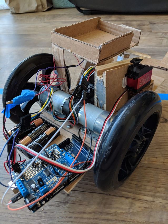
2

Darling, Robot for Roborodentia 2018               1
   Michael Le, Steven Liu                          1
           Spring 2018                             1
   1 Introduction                                  4
   2 Problem Statement                             5
   3 Software                                      6
       3.1 Functions                               6
           3.1.1 forward(int time, int speed);     7
           3.1.2 backward(int time, int speed);    7
           3.1.3 turn(int dir, int duration );     7
           3.1.4 servo_routine();                  7
           3.1.5 servo_reset();                    7
       3.2 Libraries Used                          7
           3.2.1 Wire.h                            7
           3.2.2 Adafruit_MotorShield.h            7
           3.2.3 Servo.h                           7
       3.3 Code                                    7
   4 Hardware                                     10
       4.1 Push-to-Start Button                   11
       4.2 2x4 AA Battery Case                    11
   5 Mechanical                                   12
       5.1 Flywheel Launcher                      12
       5.2 Axle Bracing                           13
       5.3 Wheels                                 14
       5.4 Mechanical Drawings                    14
   6 Budget and Bill of Materials                 17
   7 Lessons Learned                              18
       7.1 Project Management                     18
       7.2 Research                               18
       7.3 Start Early & Test Early               18
   8 Conclusion                                   18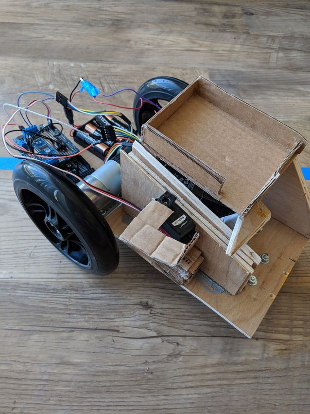
3
4
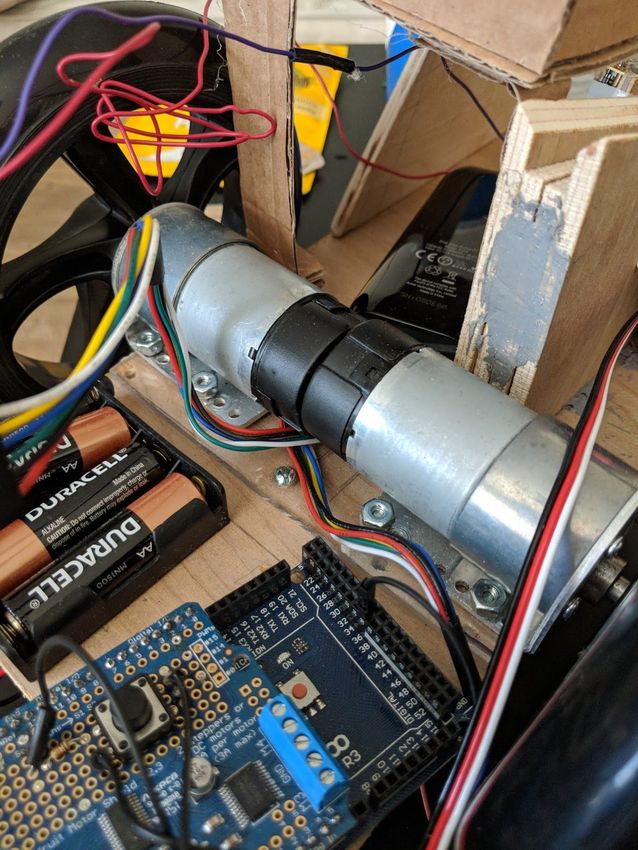
1 Introduction
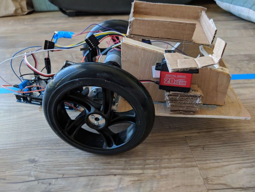
Figure 1. Side view of Darling
For our senior project, our group decided to build a robot to participate in Roborodentia
2018, an annual robotics competition overlooked by Professor Seng that takes place during open
house. When taking into consideration the classes that Computer Engineering students had to
have taken and the skills that we have developed throughout our time here on campus, a robotics
project seemed to be an appropriate culmination of both the technical and non-technical skills
that we have acquired.
Figure 2. Angled view of Darling (left)
Figure 3. Rear view of Darling (right)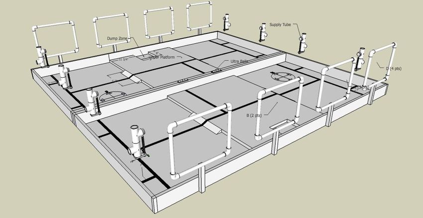
5

2      Problem Statement

                                     Figure 4. Robotics Course

         The robot was to be made from scratch, meaning no robotics kits were to be used. The
robot’s two main tasks that it had to be able to do were collecting balls from a dispenser, and
firing those balls into a target goal to be weighted for points. The objective of Roborodentia was
to compete one on one against another robot, and try to score more points than them. The robot
had to be completely autonomous without any use of radio frequency devices or transmitters, in
other words, once we started the robot, we could not affect the robot in any way, except for soft
resets, in the case penalties and deductions would apply.

                                      Figure 5. Ball dispenser
        The robot is to autonomously complete its task of running through the predesignated
course as seen in Figure 4, collecting balls from a specified ball collector as seen in Figure 5,
while it is competing against another robot that may or may not impede your robot’s ball
collecting or ball shooting.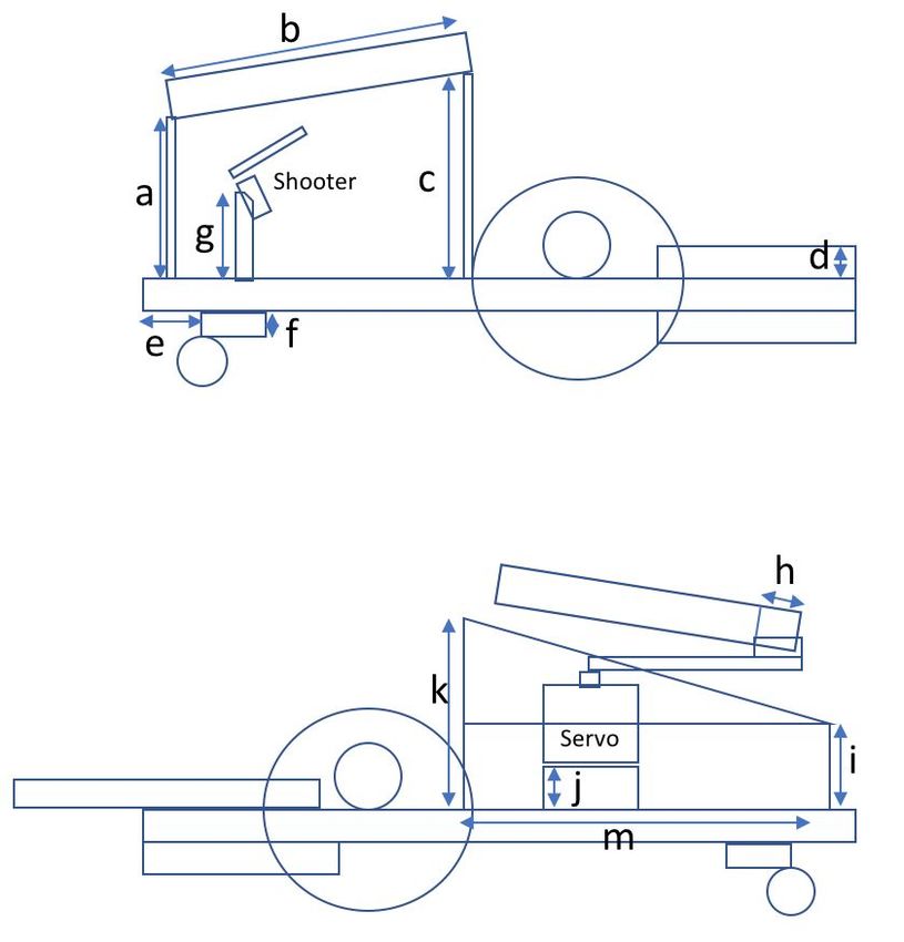
6

3      Software
        The robot was programmed using a Arduino Mega 2560 r3. We used the Arduino IDE to
develop, compile and flash the movement and shooting routines onto the onboard
microcontroller.
        An Adafruit motor shield was placed on top of the board., and the robot was coded in C,
which is optimal considering that the language is small and portable, without the use of a
garbage collector. The motor shield had a compatible library that was used to make the
controlling of the motors a lot easier. Since the robot was to be completely autonomous, our
robot doesn’t have many software components.
        The robot runs in a loop, going to collecting balls, shooting the balls, and then repeating
that process for all of the dispensers. All of the functions in our robot deal with robot movement.
We have functions made to control the motors, and code to control the servo. The functions all
accept variables that can alter the movement of the robot. For example, we have a forward()
function that takes two variables, speed, and time. By changing these variables, we are able to
control how fast and for how long the robot goes forward. Doing this made writing the routine
for the robot a lot easier, as we could simply adjust values if the robot was not going far enough,
or we wanted to optimize our speed, which came in handy when calibrating the robot to the
specific surface that the team was practicing on for that particular day.

                                     Figure 3. Software Architecture

3.1    Functions
       Basic methods and variable manipulation were used in this robotics project, without a
       need for data structures or I/O flow handling since the only input device used was the
       push button and reset button on the Arduino.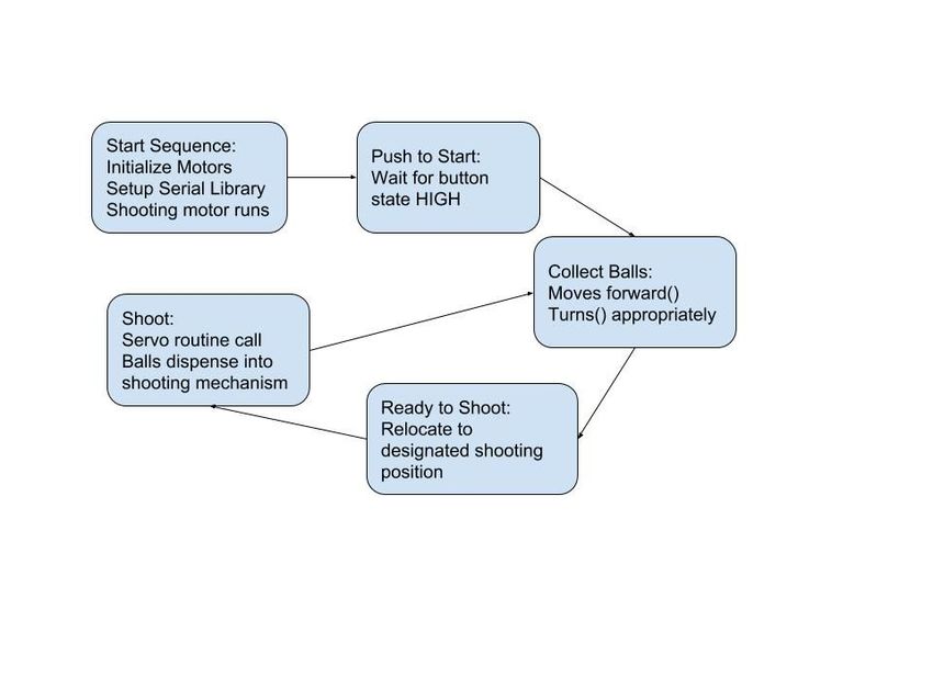
7
3.1.1 forward(int time, int speed);
Moved the robot forward for time seconds at speed speed.
3.1.2 backward(int time, int speed);
Moved the robot backwards for time seconds at speed speed.
3.1.3 turn(int dir, int duration );
Turned the robot corresponding to the value of direction. A “0” would turn the robot
right, and a “1” would turn the robot left. The duration variable controls for how long the
robot turns, also in seconds.
3.1.4 servo_routine();
Turned the servo, release the gate that kept the balls in the ball catching, effectively
shooting the balls.
3.1.5 servo_reset();
Closed the gate, allowing for more balls to be caught.
3.2 Libraries Used
The methods and wrapping defined and used by the following header files were not
written by us, and were provided by Arduino and Adafruit, the manufacturers and
developers of the components that were used.
3.2.1 Wire.h
Allowed the robot to use to motor shield. Enabled the pins that were used by the motor
shield.
3.2.2 Adafruit_MotorShield.h
Contained the functions, and structures used to control the motors.
3.2.3 Servo.h
Contained the functions needed for the use of a servo.
3.3 Code
Wire.h>
#include <
#include
#include < Servo.h>
Adafruit_MotorShield AFMS = Adafruit_MotorShield();
Adafruit_DCMotor *lMotor = AFMS.getMotor(1);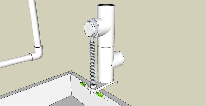
8
Adafruit_DCMotor *rMotor = AFMS.getMotor(2);
Adafruit_DCMotor *launcher1 = AFMS.getMotor(3);
Servo myservo; // create servo object to control a servo
// twelve servo objects can be created on most boards
int pos = 0;
int shootSpeed = 2
55;
const int button = 36;
void setup() {
Serial.begin(9600); // set up Serial library at 9600 bps
Serial.println("Robot starting up!");
AFMS.begin();
myservo.attach(9); // attaches the servo on pin 9 to the servo object
pinMode(button, INPUT);
}
void loop() {
Serial.println("while loop begins!\n");
int buttonState = 0;
int wentForward = 0;
while (1){
buttonState = digitalRead(button);
Serial.println(buttonState);
if (buttonState == HIGH){
if (wentForward == LOW){
servo_reset();
Serial.println("resetting servo\n");
Serial.println("button was pressed\n");
delay(500);
forward(255,2);
delay(1000);
backward(255,1);
turn(0, 500); //turn left for 500ms
forward(255,1);
turn(1, 300); //turn right for 500ms
forward(255,.5);
Serial.println("servo routine starting\n");
wentForward = HIGH;
}
servo_routine();
delay(2000);
delay(1000);
}
}
}
void servo_routine(){
for (pos = 90; pos >= 0; pos -= 2) { // goes from 90 degrees to 0 degrees
myservo.write(pos); // tell servo to go to position in
variable 'pos'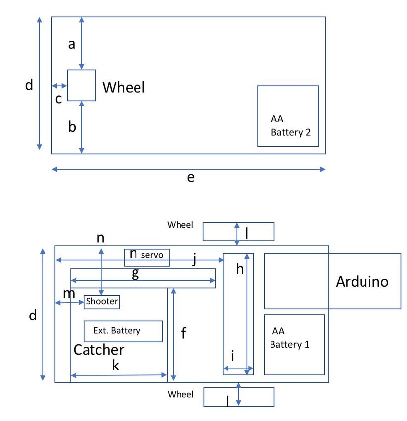
9
delay(15); // waits 15ms for the servo to reach the
position
}
}
void servo_reset(){
for (pos = 0; pos setSpeed(speed - 40);
rMotor->setSpeed(speed);
lMotor->run(FORWARD);
rMotor->run(FORWARD);
delay(time*1000);
lMotor->run(RELEASE);
rMotor->run(RELEASE);
}
// one second delay
void backward(int speed, int time){
Serial.println("Going backward!");
lMotor->setSpeed(speed - 40);
rMotor->setSpeed(speed);
lMotor->run(BACKWARD);
rMotor->run(BACKWARD);
delay(time*1000);
lMotor->run(RELEASE);
rMotor->run(RELEASE);
}
void shoot(){
launcher1->setSpeed(shootSpeed);
launcher1->run(FORWARD);
delay(2000);
launcher1->run(RELEASE);
}
//delay 4 seconds
void turn(int dir, int duration){
lMotor->setSpeed(255 - 40);
rMotor->setSpeed(255);
if(dir == 0){
//RIGHT TURN
lMotor->run(BACKWARD);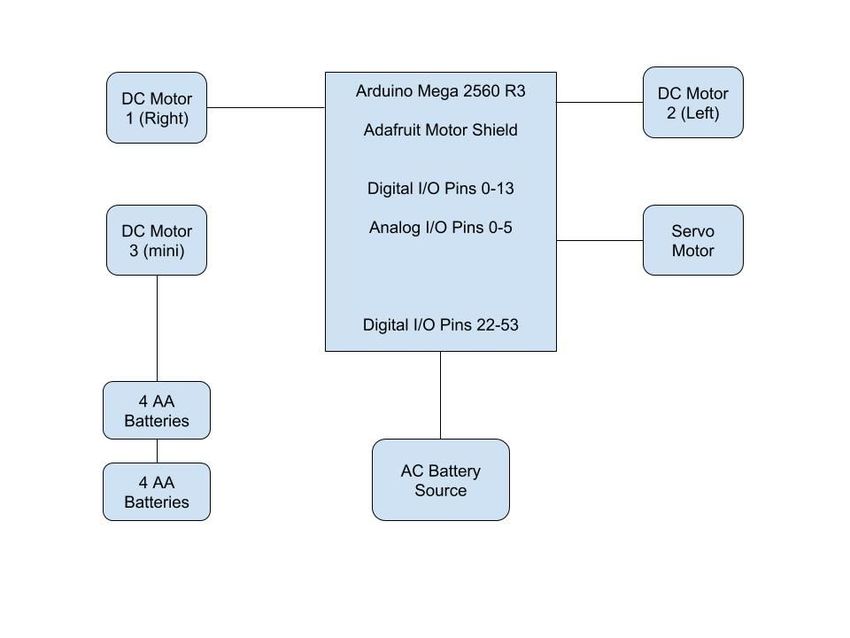
10
rMotor->run(FORWARD);
}else{
//LEFT TURN
lMotor->run(FORWARD);
rMotor->run(BACKWARD);
}
delay(duration);
lMotor->run(RELEASE);
rMotor->run(RELEASE);
}
Figure 6. Code implemented onto the Arduino
4 Hardware
There were two main hardware systems that were crucial to the functionality of the robot.
The first was the motor control system. This system is made up of the Arduino, the motor shield,
an external battery pack, the two motors, and the servo. These components in conjunction with
each other, handle the movement of the robot, and the collecting and dispensing of the balls. The
Arduino is powered via USB by the external battery pack. The motor shield is placed on top of
the Arduino, and the motors and the servo are connected to the motor shield. The start button is
also placed on the motor shield to enable push-to-start functionality.
Figure 7. Hardware Architecture11
4.1 Push-to-Start Button
One of the criteria for a competition eligible robot is the use of a push-to-start button
which when pressed at the competition’s beginning will begin the robot’s routine. The circuit
used for this button was a simple design, requiring a 5V line, ground, 10k ohm resistor and one
of the digital pins on the arduino. Although Figure 8 shows usage of a different Arduino
microcontroller, the circuit is the same.
Figure 8. Circuit used for Push-To-Start Button
4.2 2x4 AA Battery Case
A simple modification that we had to do in order to accommodate for our power issues
when driving our motors and powering our motor shield was to solder our two 4xAA battery
cases so that they were in series with each other. This way, more voltage would be supplied to
our system, allowing the proper voltage and current flow to our components, ensuring no routine
interrupts and further issues.
Figure 9. Simple batteries in Series12
The second hardware system is the shooting system. This system is composed of two
components, a motor and a battery pack. The battery pack consists of eight AA batteries. This
powers the 12V mini shooting motor continuously, which is an expensive operation considering
the current and voltage costs, but since a round in the competition is 3 minutes, and 8 AA
batteries will supply enough voltage for that duration easily, this was a price we were willing to
pay, so that there would not be any additional ramp-up time to the shots.
There isn’t any logic to this system, the motor is connected directly to the batteries, and
so while our robot is running, the motor is constantly spinning. We found that we didn’t need to
provide any start and stop logic to the shooting motor because that is pretty much handled by the
servo.
5 Mechanical
Decisions regarding the materials purchased, the mechanisms to implement, and the
physical design used on our robot development were simple and were deliberated out of
inexperience. The bulk of the design of the robot was fabricated using wood and cardboard, as
that provided a simple yet sturdy implementation to begin testing as early as possible. However,
we adapted the wood into our final design since our group lacked SolidWorks experience.
Cardboard was used to supplement an angled compartment that would catch and collect balls, as
well as attached to a servo motor that would be able to release the balls in a stream when
released.
5.1 Flywheel Launcher
Figure 10. Spin provided by flywheel design
Much deliberation was given to whether or not to use two motors on opposing sides of
the ball to launch, or just one motor to launch the ball. Ultimately, after several drafts, we had
determined the use of two motors would enforce conflicting spins on the ball, which would
actually decrease distance of the balls shot as well as adding complexity to forcing both motors
to rotate at the same speeds.13
Figure 11. Theoretical trajectories of ball with varying initial velocities
Projectiles were planned according to launch from the robot at a 45 degree angle, and so
with an initial velocity, the robot was designed to shoot from a fixed, designated position, and
calibrated to only complete shots from a specified position on the board.
5.2 Axle Bracing
Figure 12. Laser cut acrylic axle bracing
A simple, yet often overlooked challenge when developing a hand-calibrated robotics
project is how straight the robot will actually go. If the motors are not mounted correctly, any
deviation in angle to each other will cause the robot to traverse in an arc, while the robot is
intended to move forward. In order to combat this obstacle, a piece of acrylic was added as a
makeshift axel to align the motors to each other so that they will not deviate from their calibrated
paths. However, our robot encountered issues traversing in a straight line because of a defective
motor that was discovered during the final parts of testing.14
5.3 Wheels
Another design decision we made very early in the development of our robot was the
size, and number of wheels we should use. Bigger wheels would go up the ramp easier, but
might be less precise. In the end, we settled for large wheels. We weighed getting up and down
the ramp to be more important than precision.
In terms of the number of wheels, the debate was between using two or four motorized
wheels. Four wheels would would provide more power, but at the same time aligning four
wheels to be perfectly parallel with each other would have been much more difficult than with
just two wheels. Four wheels would also drain the battery pack more quickly.
A third decision we made involving the wheels was what to put on the back of the robot
to support it. Two wheels on either side of the robot would mean the robot would tip back and
forth like a see-saw. Something needed to be put on the back of the robot to prevent this, and the
debate was between legs with little friction, or a third wheel that is non motorized. We settled on
the third wheel, because it was easier to get. If we had the means to 3D print something, then we
would have leaned more towards the legs, but because we didn’t, we settled on the method that
was easier to procure.
5.4 Mechanical Drawings
a. 2 in.
b. 2 in.
c. 1 in.
d. 5.5 in.
e. 12.25 in.
f. 4 in.
g. 6 in.
h. 5.5 in.
i. 2 in.
j. 7 in.
k. 5 in.
l. 1 in.
m. 2.68 in.
n. 2 x 1 in
Figure 13. Top and Bottom View Mechanical Drawing15
a. 4 in.
b. 4.875 in.
c. 4 in.
d. 2.5 in.
e. 1 in.
f. 1.5 in.
g. 2 in.
h. 1 in.
i. 2 in.
j. 1.5 in.
k. 4 in.
Figure 14. Side Views Mechanical Drawings
a. 2 in.
b. 2.5 in.
c. 1 in.
d. 1 in.
e. .5 in.
f. .5 in.
Figure 15. Shooter Dimensions16
a. 1.75 in.
b. 1 in.
c. 1 in.
d. 2 in.
e. 1 in.
f. 2 in.
g. .2 in.
Figure 16. Servo Dimensions17
6 Budget and Bill of Materials
Item Quantity Cost Per Shipping Fees Total Cost
Wheel Adapter 2 4.95 8.95 18.85
Wheels 2 5.95 0.00 11.90
Screws 1 1.75 00.00 1.75
DC Motors 2 12.00 0.00 24.00
Arduino Mega r3 2560 1 16.15 0.00 16.15
Adafruit Motor Shield 1 18.99 0.00 18.99
Small Motors 2 17.95 1.97 37.87
Mounting Brackets 1 7.95 00.00 7.95
LeWan Soul Servo Motor 1 17.99 00.00 17.99
Small wheels 1 4.95 19.95 24.90
2x4 AA battery holder 1 6.95 00.00 6.95
Rechargeable AA batteries 1 18.99 0.00 18.99
Wood 1 7.32 0.0 7.32
Fuzeit surface glue 1 6.97 0.00 6.97
Wood screws 1 1.18 0.00 1.18
Total Cost: $221.76
Overall, the budget for this project was very manageable. We were able to get $200 of
funding from the CPE Office, so the majority of the project was covered by that. Our goal was to
stay as close to $200 as possible, and we were able to successfully do that. A few of our
purchases were questionable and done prematurely as a precaution. The Fuzeit Surface Glue that
was purchased was redundant since hot glue proved to be a better solution because it dried faster
and proved to be a better adhesive. We had purchased rechargeable AA batteries, but had not
accounted for the voltage requirement in our circuit, and our lack of space for a 3rd battery case
compartment. Rechargeable lithium batteries individually hold a smaller voltage, so we would
need to hold more rechargeable batteries and would therefore need to implement a 3rd battery
case compartment in series, and that would require more real estate on the robot. So we had just
used regular AA batteries.18
7 Lessons Learned
This project was an invaluable lesson for us, not only in robotics, programming,
machining, but in good engineering practices as well.
7.1 Project Management
The largest takeaway we had after completing this project is that making a good design
before you start building anything is crucial in making an effective project. During the
construction of our robot, we would often go into the machine shop with a vague idea of what we
wanted to get done, and so not much would actually done during our time there, even though we
spent numerous hours machining various parts. The lack of project management experience on
both of our parts had led to a poor project flow and directly affect the project’s local scope.
Having a concrete and precise idea of what we wanted to get done (i.e. exact measurements for
parts) would have helped us in being much more productive and efficient with our time.
7.2 Research
Another lesson we learned through this project was that more research would have
definitely helped us. Both group members are Computer Engineering majors, with little to no
experience in machining and mechanical design. Both of us got red tags just for the purpose of
completing this project. This lack of mechanical experience proved to be huge disadvantage for
us. We noticed what a lot of other groups did was 3D print their parts, or use laser cut acrylic.
Both of these methods have a lot more precision than cutting pieces of wood with various saws,
and would have saved us tremendous time. Taking the time to invest in those skills would have
helped us greatly, and would have definitely improved the performance of the robot.
7.3 Start Early & Test Early
A poor oversight on our part was the late finalization of a working prototype. It was not
until the day before the seeding round that we were able get a robot able to run, if we had
developed a catcher sooner, then we would have noticed that the Adafruit motor shield would
reset during its routine due to lack of consistent current flow. This bug was a huge hurdle since
we had not anticipate it and it had ultimately rendered our robot unable to compete in time.
Having a working prototype early also allows room to implement more components, such as
sensors to detect the line and goal posts, adding complexity and functionality to the robot.
8 Conclusion
This project was a great experience to cap off our fourth years. We were able to get new
experience in many fields, and learned different ways to refine what skills we already had.
Although we were not able to actually complete in Roborodentia, the experience of building the
robot, and all of the ups and downs that we faced through the process, matured us as engineers
and problems solvers. A robotics project is a great way to culminate skills acquired in the major
Computer Engineering classes, such as Programmable Logic, Microcontrollers, Digital and
Integrated Circuits.You can also read