Investigation of the influence of tank geometry on a vessel's stability under free surface effect when in coastal waters
←
→
Page content transcription
If your browser does not render page correctly, please read the page content below

Journal of Physics: Conference Series

PAPER • OPEN ACCESS

Investigation of the influence of tank geometry on a vessel’s stability
under free surface effect when in coastal waters
To cite this article: Ross Fuge and Jahir Rizvi 2021 J. Phys.: Conf. Ser. 1834 012010

View the article online for updates and enhancements.

                               This content was downloaded from IP address 46.4.80.155 on 29/07/2021 at 02:37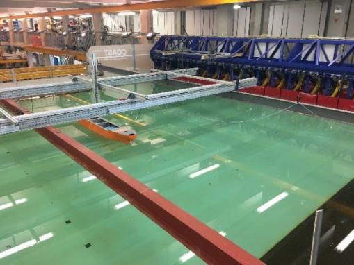
2020 International Joint Conference on Civil and Marine Engineering (JCCME) 2020                                         IOP Publishing
Journal of Physics: Conference Series                         1834 (2021) 012010               doi:10.1088/1742-6596/1834/1/012010

Investigation of the influence of tank geometry on a vessel’s
stability under free surface effect when in coastal waters

                     Ross Fuge1,* and Dr Jahir Rizvi1
                     1
                      School of Engineering, Computing and Mathematics, Faculty of Science and
                     Engineering, University of Plymouth, Drake Circus, Plymouth, PL4 8AA, UK

                     *E-mail: rfuge98@gmail.com

                     Abstract. Tank sizes on liquid cargo carriers are becoming larger to minimise wasted spaces
                     on-board and maximise payload capacity. This trend can significantly affect a vessel’s stability
                     and its design. Therefore, this paper investigates whether spherical tanks provide better
                     stability than a traditional tank formed with vertical sides under a range of free surface
                     scenarios. The motions of a model liquid cargo carrier hull with various sizes of tanks and
                     various fill levels has been investigated in a coastal basin. Regular waves of various heights
                     and frequencies have been generated and the rolling motions of the hull have been documented.
                     Results have shown that spherical tanks offer less free surface effects compared to vertical
                     sided tanks thus create less rolling motion. In contrast, when the hull has four tanks, all of
                     those with free surfaces, the vertical sided tanks provide better stability up to 50% fill levels
                     whereas spherical tanks induce less roll between the fill levels 50% and 100%.

1. Introduction
With increasing demand for liquid cargo to be transported [1] , there is a growing interest in using
unbaffled tanks, instead of baffled tanks to maximise cargo carrying capacity [2]. It is of importance to
maximise space to maximise profit while not putting the safety of the vessel at risk. This highlights a
gap in research regarding direct comparisons among various tank designs. Typically, vertical sided
tanks are used in crude oil tankers for cargo storage [3] . Cruise ships also utilise those tanks for
potable water storage. However, spherical tanks are utilised on some LNG vessels [4] [5]. This design
is favourable mainly due to the pressure that the LNG is stored under [6] . However, spherical and
vertical sided, both types of tanks typically have large volume of liquids with varying free surfaces.
    A vessel with partially filled tank(s) and exposed to external forces (e.g. wind and waves) results in
sloshing within the tank(s). Sloshing is a nonlinear movement of liquids inside tanks that are not full
or completely empty [7]. Liquid movement creates dynamic loads on the tank that are transmitted into
the vessel [8] . Besides the impact forces on the tank walls, sloshing may also have an effect on the
vessel’s motions [9].
    No known research has previously compared between spherical and vertical sided tank designs.
Therefore, this paper looks to identify and compare the differences when the tanks have free surfaces
and are subjected to wave loads. This paper compares vertical sided tanks to spherical tanks with a
range of free surfaces through a study conducted using a model liquid cargo carrier hull within a
coastal basin at the University of Plymouth, UK.

              Content from this work may be used under the terms of the Creative Commons Attribution 3.0 licence. Any further distribution
              of this work must maintain attribution to the author(s) and the title of the work, journal citation and DOI.
Published under licence by IOP Publishing Ltd                          1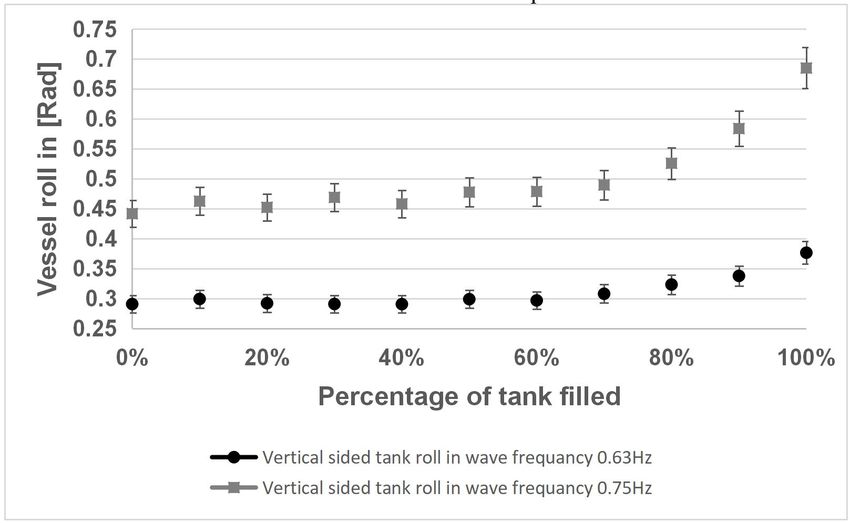
2020 International Joint Conference on Civil and Marine Engineering (JCCME) 2020                        IOP Publishing
Journal of Physics: Conference Series                1834 (2021) 012010            doi:10.1088/1742-6596/1834/1/012010

   The aim of this paper is to identify how both tank designs affect a liquid cargo carrier’s roll
motions when the vessel experiences wave loads in coastal waters. The aims have been achieved
through direct comparison between the two tank designs and identifying how increasing levels of fluid
within the tanks affects the vessel’s stability. The effects of wave heights and frequencies have also
been investigated to identify the effect this has on the vessel as a comparison between the two tank
designs.

2. Methodology
It is common to use a wave machine and/or towing tank for vessel testing [10] . In recent years,
computer software has become more capable of doing this [11] . However, using a combination of
physical and computer modelling is more efficient, as physical modelling is more expensive but
allows confirmation that computer-based results are accurate.
    To achieve the aims of the project, model spherical tanks were manufactured in-house using
laboratory facilities as shown in figure 1 whereas off the shelf food containers (shown in figure 2)
were used as model vertical sided tanks. The experiment was conducted using the University of
Plymouth’s coastal basin and model hull was utilised and the vertical sided tanks were installed,
shown in figure 4.
    The model hull used for this experiment has a depth of 20cm. LNG vessels typically have a depth
of 26 metres, therefore, it would be feasible to consider an LNG vessel with a depth of 20 metres for
the purpose of this experiment [10] . This then allows a scale of 1cm:1m to be used. The size of the
hull allowed for four tanks to be installed upon it. Using steady wind at a speed of 30 knots over 24
hours with a fetch of 340 miles, this would equate to an end average wave height of 3 metres and a
significant wave height of 5 metres [12]. This has allowed for a sensible model wave height of 2- and
3-metre waves to be used in the basin.

   Figure 1. Manufactured sphere tanks left on their            Figure 2. Off the shelf food container used
   supports. Behind the spheres is the model vessel.                  as model vertical sided tank.

2.1. Tank manufacturing
The spheres used in the experiments were manufactured by hand laminate with weaved glass fibre and
epoxy resin. First, pre-inflated soccer balls of 23 cm diameter were wrapped with glass fibre fabrics
prior to apply the resin. A coat of yacht varnish was also applied to ensure the spheres were watertight.
The capacity of the spheres slightly varied between each sphere. This is believed to have been the
result of the balls being pre-inflated with air and thus the exact dimension would vary.

2.2. Experimental set up
The centre of gravity (CoG) was calculated for the spheres and the vertical sided tanks. The vertical
sided tanks were raised from the hull bottom to keep the CoG of the tanks (when at maximum capacity)
at the same height as that of the spherical tanks.
    The hull has been fitted with four tanks, that have been assigned a tank number running from the
bow of the vessel to the stern, starting with the most forward tank being “Tank 1”. The spherical tanks
have the following capacities; tank 1 – 5.0 litres, tank 2 – 5.2 litres, tank 3 – 5.1 litres and tank 4 – 4.7

                                                           2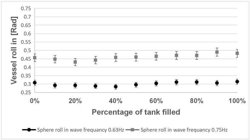
2020 International Joint Conference on Civil and Marine Engineering (JCCME) 2020 IOP Publishing
Journal of Physics: Conference Series 1834 (2021) 012010 doi:10.1088/1742-6596/1834/1/012010
litres. Fill levels for each sphere were adjusted accordingly, while vertical sided tanks, made from
food containers, were purchased with a total capacity for each tank as 5.2 litres. The minor
discrepancies in size (up to 0.5 litres) would only have a minor impact, which can be addressed
through discounting anomalies.
The hull was tested under two different conditions, one with vertical sided tanks installed and
another with spherical tanks installed. Initial controls were taken with empty tanks installed on the hull.
These were then exposed to wave heights of 2 or 3 cm and at a frequency of 0.75 Hz or 0.63 Hz.
Tests were conducted for 2 minutes and each test was repeated 3 times with a 2-minute interval to
allow time for the water to settle. A six degrees of freedom motion sensor (6DOF) was installed at the
hull’s CoG. The 6DOF is an analogue sensor that includes outputs of three gyroscope/rate sensors and
three DC accelerometers. The 6DOF recorded hull motions, with the X axis has been assigned to the
direction of the waves, Y axis longitudinally to the waves and Z vertically. The 6DOF is calibrated at
+24 ⁰C at 10 Vdc. The sensitivity is in 20 mV and has an accuracy of ±15%.
The volume of liquid within the tanks was increased by 10% per test up to the maximum volume or
until the vessel became too unstable and risked damaging the 6DOF. Results generated from the 6DOF
have been recorded in radians and then organised highest to lowest. The highest and the lowest 1%
has been averaged as results have been taken at set timed intervals. There is also a discrepancy within
the wave height of ±1 cm.
2.3. Coastal basin set up
Distance of the hull from the wave generation paddles was 583 cm. Three wave gauges were used to
determine the height of the wave (see figures 3 & 4).
Wave gauge 1 was located 222 cm from the hull in the direction of the travel of the wave.
Wave gauge 2 was located 100 cm in the direction of the travel of the wave.
Wave gauge 3 was located 98 cm beyond the hull away from the direction of travel of the wave.
The beach started 251 cm from the port side of the vessel.
The water line ended 910 cm from the port side of the vessel.
To improve data accuracy, before testing commenced each day, the three wave gauges were
calibrated. The coastal basin was set to a water depth of 500 mm, the maximum daily variation to this
was ±10 mm. This change in level will have had an impact upon the waves generated. However, this
was minimised by topping the basin up with water daily to achieve the correct working level.
The wave gauges are calibrated using the manufactures supplied computer program, this involved
setting the correct basin working water level of 500 mm. The wave gauges where raised 10 cm, from
there working level and the water allowed to settle before calibrating. The gauges where then lowered
10cm, from there working level and the water allowed to settle, then calibrated. Lastly, the gauges
were set to the working level and calibrated. The program uses the current flow across the sensors at
each depth to calculate the changes in water level.
Figure 3. The hull’s setup within the coastal basin showing the wave generation paddles along with
the supporting structure holding the vessel in position. The wave gauges are fixed to the supporting
structure.
3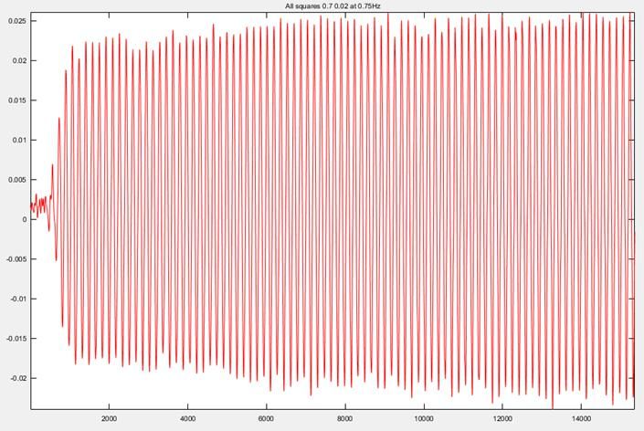
2020 International Joint Conference on Civil and Marine Engineering (JCCME) 2020                        IOP Publishing
Journal of Physics: Conference Series                1834 (2021) 012010            doi:10.1088/1742-6596/1834/1/012010

                Figure 4. Experimental set up details within the coastal basin (Not to scale).

3. Results
Upon completion of testing, the generated data has been imputed to Microsoft Excel and MATLAB to
generate workable data to compare between different run settings. All test setups were repeated three
times to improve the accuracy of the data and allow for anomalies within the results to be identified.
The results from all three runs have been averaged using the maximum 1% of roll data generated.

3.1. Wave data
All wave height data utilised has been inputted into MATLAB software and de-noised to develop
readable and accurate sinusoidal wave graphs. This software also has developed the maximum and the
minimum heights of the waves. A sample of wave data primarily from wave gauge 1 (figure 5) has
been taken to appraise how the waves formed compared to desired wave height and thus how this
could have affected the data generated.

  Figure 5. Waves generated with a wave set height of 0.02 m and frequency of 0.75 Hz. Data points
                                    taken from wave gauge 1.
   It has been observed that there was a variation between the set wave height and the wave height
generated. This has resulted in some deviation within the results, however, as an average of maximum
1% of roll was taken this has minimised discrepancies within varying wave heights. This also gives
results closer to what would be expected within a real-world scenario as natural waves will have
variable heights. It has been observed that some wave gauges appeared to have failed to calibrate
correctly in some of the data. The wave gauge results have been compared with the other two gauges
to determine the actual height of waves and thus the defective wave gauge has been discounted from
the results.

                                                           4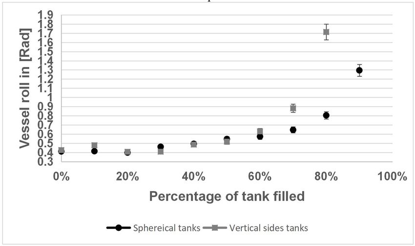
2020 International Joint Conference on Civil and Marine Engineering (JCCME) 2020                        IOP Publishing
Journal of Physics: Conference Series                1834 (2021) 012010            doi:10.1088/1742-6596/1834/1/012010

3.2. Hull stability
The hull’s stability has been compared among three variables: wave height, frequency and the tank
shape. From the results, it is surprising to see that the hull becomes slightly more stable when it had a
low percentage of water in the tanks. It was expected that the roll angle would increase when the free
surface was increased. This is likely due to the CoG of the vessel becoming lower.
   The wave data has shown that there is some variation between the wave set height and the wave
height achieved. This has varied slightly between run to run of the same setting. The results shown
within the following figures have been calculated using the highest or the lowest one percent
depending on the direction of roll. This equates to around 157 results per direction of roll. All figures
within the “hull stability” show the hull’s roll angle in radians and when the hull was side-on to the
waves.
   Tests were repeated by increasing the fill levels of all the tanks by 10% for each test setup, wave
height and frequency. Once all variations were conducted for one tank design, the tanks were changed,
and the same tests conducted on the hull with the other tank design. These was repeated until the hull
became too unstable and risked damaging the 6DOF sensor located in the hull.

3.2.1. A wave height of 0.03 m and at a frequency of 0.63 Hz
Figure 6 shows the average results for a wave height of 0.03 m and at a frequency of 0.63 Hz. It is to
be noted that the vertical sided tanks resulted in less roll between 10% and 60% fill levels than that of
the spherical tanks. Greater than 60% fill level, the spherical tanks impact upon the hull’s stability is
less than that of the vertical sided tanks.
    The roll increases quicker after 60% of fill level as seen in figure 6. It is to be noted however, that
although the roll of the hull with spherical tanks increases, the roll angle is lower than that of the
vertical sided tanks. It has also been observed that the hull when fitted with spherical tanks was able to
hold a greater volume of water before becoming too unstable to continue testing.
    Fascinatingly at 30% fill level, the vertical sided tanks only induce a roll of 0.408 radians whereas
spherical tanks have an average roll angle of 0.461 radians. At 70% fill level, the vertical sided tanks
induce a roll of 0.881 radians whereas the hull with spherical tanks had a roll of 0.645 radians.

 Figure 6. Comparison between vertical sided tanks and spherical tanks with a wave height of 0.03 m
                                 and at a frequency of 0.63 Hz.

3.2.2. A wave height of 0.02m and at a frequency of 0.75 Hz
Figure 7 shows all tanks filled with varying percentage of water with a wave height of 0.02m and at a
frequency of 0.75 Hz. It was noted that in this set up, the hull handled in a similar manner to when the

                                                           5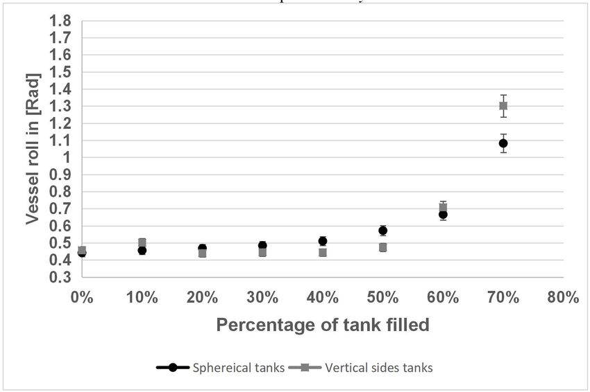
2020 International Joint Conference on Civil and Marine Engineering (JCCME) 2020                        IOP Publishing
Journal of Physics: Conference Series                1834 (2021) 012010            doi:10.1088/1742-6596/1834/1/012010

wave height was 0.03 m and at a frequency of 0.63 Hz. However, the hull became unstable at 70% fill
level for both types of tanks.
    The hull has greater roll from the spherical tanks between 20% to 50% fill levels. However, past
50% fill level, the spherical tanks become more stable. It can be said that at 40% fill level, the
spherical tanks have an average roll of 0.51 radians whereas the vertical sided tanks’ average roll is
only 0.44 radians, a difference of 15%, when at a wave height of 0.02 m and wave frequency of 0.75
Hz.
    In contrast, when the tanks were at 70% fill level, the roll with spherical tanks was only 1.08
radians whereas the vertical sided tanks achieved an average roll of 1.3 radians, a difference of 20%. It
is expected that this trend would have continued if it had been possible to test to 100% capacity. Both
tank designs would have increased the roll of the hull whereas it is predicted that the roll from the
spherical tanks would have been less than that experienced by the vertical sided tanks.

 Figure 7. Comparison between vertical sided tanks and spherical tanks with a wave height of 0.02 m
                                 and at a frequency of 0.75 Hz.

3.2.3. Only filling one tank identified as tank two
Figure 8 compares vertical sided tanks with a wave height of 0.02 m and frequency of 0.75 Hz against
the same wave height and at a frequency of 0.63 Hz. Figure 9 shows the same set up, however using
the spherical tanks. This has shown that changing just the frequency of the waves has a direct impact
upon a hull’s stability. It is noted in both figures 8 and 9 that the hull handles comparatively the same
rolling motion. Although the roll angle has increased by a factor of approximately 1.5 when the wave
frequency is increased from 0.65 Hz to 0.75 Hz.
    Although the angle increased, both followed the same pattern. As can be seen with the spherical
tank between 10% and 50% fill levels in figure 9, the stability of the hull is improved. Whereas for the
vertical sided tanks, the stability did not improve once the fill levels were increased, it stayed at a
constant stability between 10% and 60% fill levels as seen in figure 8.
    Surprisingly, the vertical sided tank shows a similar trend to that of the spherical tanks up to 80%
fill level. After this, it is seen that the hull’s roll increases. The increase in roll for the vertical sided
tank is probably because the top of the container was much higher in the hull compared to that of the
sphere. Just using spherical tank 2, it has been observed in both frequency settings to have altered the
roll of the hull less than that of the vertical sided tanks.

                                                           6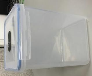
2020 International Joint Conference on Civil and Marine Engineering (JCCME) 2020                        IOP Publishing
Journal of Physics: Conference Series                1834 (2021) 012010            doi:10.1088/1742-6596/1834/1/012010

   The roll angle when at 0.63 Hz wave frequency and 100% full is on average 0.3139 radians.
Whereas at 10% fill level, the average roll is 0.2919 radians. In contrast, for the vertical sided tank at
100% fill level, the roll has increased to 0.3765 radians. This highlights the effect of the higher mass
within the hull. At 10% fill level, the vertical sided tank has a similar roll angle of 0.2993 radians. The
negative roll recorded shows that the hull in both directions experienced the same motion behaviour.

   Figure 8. Vertical sided tank 2 only being filled at varying percentages showing a comparison of
                        waves at 0.02 m and a frequency of 0.75 Hz or 0.63 Hz.

Figure 9. Spherical tank 2 filled at varying percentages showing a comparison of waves at 0.02 m and
                                   a frequency of 0.75 Hz or 0.63 Hz.

4. Conclusion
It is seen in all scenarios tested that vertical sided tanks with increasing percentage of liquid above
50% fill levels have an increased impact upon the vessel. Otherwise, the vertical sided tanks had less
of an impact upon the vessel’s stability. Above 50% fill levels, the vessel’s roll increases for the

                                                           7
2020 International Joint Conference on Civil and Marine Engineering (JCCME) 2020 IOP Publishing
Journal of Physics: Conference Series 1834 (2021) 012010 doi:10.1088/1742-6596/1834/1/012010
vertical sided tanks whereas it stabilises for the spherical tanks. Although both tanks have the same
CoG, there is more mass higher in the vessel in the vertical sided tanks than in the spherical tanks.
Overlaying the data with all tanks filled shows that at 20% fill level, the vertical sided tanks did not
affect the vessel’s stability as greatly when compared to the spherical tanks. Between 50% and 60%
fill levels, the spherical tanks’ impact upon the vessel becomes less than that of the vertical sided tanks.
As the fill level increased past 60%, the stability of the spherical tanks was greater than that of the
vertical sided tanks.
It is believed that the larger roll experienced by the vessel between 20% and 50% fill levels is due
to the sphere having a greater possible surface area below 50% capacity compared to the vertical sided
tanks. However, past 50% of capacity the space reduces as the sphere curves back on itself. Thus,
experiencing a smaller surface area, and reducing the effect of the sloshing water. This data opens
questions on the possibility of hybrid tanks with vertical sided tank sides in the lower section of the
tank and opening to a spherical top half.
This also highlights the importance of correct tank designs with how the vessel and tank shall be
operated. From the data produced for this paper, the frequency of the waves greatly impacts the
vessel’s stability.
Acknowledgments
My utmost thanks to Dr Richard Cullen for his support and expertise to enable me to manufacture the
spheres out of composites. I would also like to thank Andrew Oxenham and everyone from the
COAST laboratory in the University of Plymouth for allowing me to use the coastal basin and their
support in setting up my testing.
References
[1] Shell 2019 Shell LNG Outlook 2019 [Online]. Available: https://www.shell.com/energy-and-
innovation/natural-gas/liquefied-natural-gas-lng/lng-outlook-2019.html. [Accessed 19th
January 2020].
[2] Busciglio A Caputo G and Scargiali F 2013 Free-surface shape in unbaffled stirred vessels:
Experimental study via digital image analysis Chemical Engineering Science vol. 104 no.
1st pp. 686 - 880.
[3] National Research Council 1991 Tanker Spills: Prevention by Design 1st ed Washington DC:
The National Academies Press.
[4] Vanem E Anta P Østvik I and de Comas F, 2007 Analysing the risk of LNG carrier operations
Reliability Engineering and System Safety vol. 93 no. 9.
[5] Mokhatab S Jaleel J and Wood V 2014 LNG Fundamentals Handbook of Liquefied Natural
Gas (Oxford: Gulf Professional Publishing) pp. 1-106.
[6] Kumar A 2017 Why do some fuel tanker ships use spherical tanks rather than cylindrical ones?
[Online]. Available: https://www.quora.com/Why-do-some-fuel-tanker-ships-use-spherical-
tanks-rather-than-cylindrical-ones. [Accessed 29 January 2020].
[7] Brizzolara S Savio L Viviani M Chen Y Temarel P Couty N and Hoflack S 2011 Comparison of
experimental and numerical Ships and Offshore Structures vol. 6 no. 1 pp. 15- 43.
[8] Graczyk M Moan T and Wu M 2007 Extreme sloshing and whipping-induced pressures and
structural response in membrane LNG tanks Ships and Offshore Structures vol. 2 no. 36, pp.
201 - 16.
[9] Twillert E 2015 The effect of sloshing in partially filled spherical LNG tanks on ship motions
1st ed (Delft: Delft University of Technolog).
[10] Babicz J 2015 Encyclopedia of Marine Technology, 2nd ed Helsinki: WÄRTSILÄ corporation.
[11] Maeda H Williams J and Silverleaf A 1991 Modelling Techniques for Dynamics of Ships [and
Discussion] Philosophical Transactions: Physical Sciences and Engineering vol. 334 no.
1634 pp. 307 - 17.
[12] Dorn W 2013 Oceanography and Seamanship Second edition ed (Toronto: Second Story Press).
8You can also read