Design and Development of a Cooler used for Air Cooling and Refrigeration - IJRTE
←
→
Page content transcription
If your browser does not render page correctly, please read the page content below

International Journal of Recent Technology and Engineering (IJRTE)
ISSN: 2277-3878, Volume-8 Issue-5, January 2020
Design and Development of a Cooler used for
Air Cooling and Refrigeration
Bhupendra Sahare, Chhavikant Sahu
Abstract: In this research paper we have discussed the II. LITERATURE REVIEW
utilization of a cooler for air cooling as well as refrigeration. The
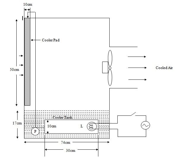
purpose of this paper is to design modification of the existing Classic book by Watt [1] is an excellent qualitative review
design of, in which a refrigeration box is made of mild steel is of the various concepts, devices and systems, which had been
attached inside the cooler tank and this tank of cooler is insulated in vogue by that time, though the corresponding quantitative
by rubber pad from outside to avoid any loss of heat. All the analysis was missing. The two papers by Mathur and Jain [2,
surfaces of the box are in contact with tank water except the front
face which is door of a refrigeration box. The proposed model is
3] presented mathematical model showing the performance of
experimentally validated by conducting a series of experiments in the air cooler fitted in a room, are typical publications in this
a controlled atmosphere inside a room in the climate of Raipur, area in 70s and early 80s. Singh et al [4] investigated the
Chhattisgarh, India. Box is loaded with fruits / vegetables and dependence of tropical summer index (TSI) in a room cooled
parallel to this, the same quantities of fruits / vegetables are kept by air washer type air cooler. Optimum values of the
outside in the room and daily weight loss is measured.
operating parameters viz packing factor, pad area, and the
Keywords: Air cooler, Evaporative cooling, Mathematical
modeling and Refrigeration box. airflow rate for which the mean daily TSI is minimum has
been determined for a typical set of a cooler, room and
I. INTRODUCTION meteorological conditions. Singh et al [5], developed a
mathematical model characterizing optimization of the
Evaporative air cooler generally referred as desert cooling performance of air cooler, and defined two new
conditions which determine the cooling capacity of this
coolers. Nowadays it is very popular for space cooling cooler. Dowdy et al [6] evaluated heat and mass transfer
providing a cheap alternative to standard air conditioning coefficient by conducting experiments with the help of
systems. It operates without the ozone harming various types of cellulose pads thickness. Sodha et al [7]
hydro-chlorofluorocarbons (HCFCs) which is used by analyzed the cooling tower’s thermal performance which is
refrigeration based systems as compare to air conditioning fitted in the building in terms of discomfort index for dry and
(AC) units. Northern regions of India are the very good warm climates. Singh, Tulsidasni, Swhney and Sodha [8-13]
locations for execution of this device when sufficient amount in series of 6 papers reported their work on optimization of
of water is available, low installation and operating cost in this coefficient of performance (COP), cooling potential, thermal
region than the AC units. Although the utilization of desert performance in building, recirculation effect on cooled room
coolers for space air conditioning is an effective alternate to and design evolution has been investigated in IEC (Indirect
compressors-based air conditioning systems but still the poor Evaporative Cooling) system. Plasencia et al [14] developed a
effectiveness of the evaporative cooling-based desert cooler new model which is based on transfer of heat and mass for
in humid climatic conditions is one of the reasons for the IEC; few simplifications were incorporated to make this
decline in popularity of evaporative cooling-based device. model as user friendly used for analysis of energy as well as
Still it is suitable in many parts of the country due to favorable adaption of system. Camargo et al [15] presented an
climatic conditions; it may be categorized as direct operational concept for both type of cooling systems and
evaporative cooling system and indirect evaporative cooling generated equations for mass and heat transfer between warm
system. Direct evaporative cooling introduces water directly air and wetted media. Above researches and mathematical
into the supply airstream. Water absorbs heat from supply air; models has been limited up to the conditioning of air coming
it evaporates and cools the air. Indirect evaporative cooling out of the coolers, and to increase the saturation efficiency or
lowers the temperature of air by the arrangement of some type effectiveness of cooler; however the use of cooled water
of heat exchangers; secondary sir is cooled by water and then stored in tank was not at all explored. This gap of not using the
successively cools the primary air. coolness of cooler water has been identified as a research gap
and thus becomes the main objective of the present work. The
coolness stored in tank water can be utilized for mild
Revised Manuscript Received on January 15, 2020.
* Correspondence Author
refrigeration or to cool. As in present work it is suggested that
Bhupendra Sahare*, M.Tech Student, Department of Mechanical the cooler water can be utilized to cool the objects stored in
Engineering, Government Engineering College Jagdalpur, Chhattisgarh, the cooler tank.
India. Email: bhupendrasahare24@gmail.com
Chhavikant Sahu, Assistant Professor, Department of Mechanical
Engineering, Government Engineering College Jagdalpur, Chhattisgarh,
India. Email: cksahu@gecjdp.ac.in
Published By:
Retrieval Number: E6886018520/2020©BEIESP Blue Eyes Intelligence Engineering
DOI:10.35940/ijrte.E6886.018520 5192 & Sciences Publication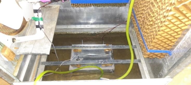
Design and Development of a Cooler used for Air Cooling and Refrigeration
III. MATHEMATICAL MODELING P R1T 2 R2T R3 , (8)
where R1 6.36 Nm 2 oC 2 , R2 112.8 Nm 2 o C 1 and
A. Determination of exit air temperature of cooler and
exit water temperature on pad R3 1890Nm2 .
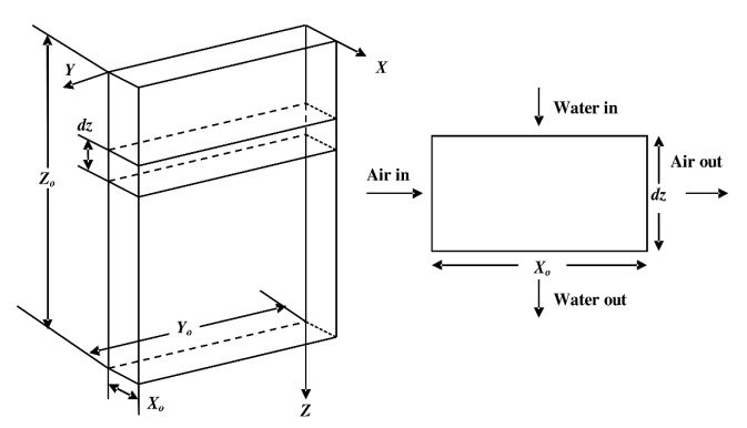
Following earlier mathematical model proposed by Sodha From Eqs.(3),(4),(5),(6),(7) and (8) one obtains,
and Somwanshi (2012), considering an evaporative pad (Fig. dTw
ATw2 BTw C , (9)
1), having water flow from up to down tray in z direction, flow dz
of water is normal to the pad in x direction. Dependence of where,
water temperature on z direction is taken into consideration. mwcw ,
N1
hc Fp xo yo
K1 1 exp( xo ) / xo ,
A R1Cn / N1 ,
B ( R2Cn K1 ) / N1 and
C [Cn R1 Tai 2 Tai ( K1 C R ) C R ( 1)] / N1
n 2 n 3
Integrating Eq.(9) one obtains,
Tw ( B / 2 A) C1
exp( 2 AC1 z ) ,
Tw ( B / 2 A) C1
where,
T ( B / 2 A) C
Fig.1 Pad profile and elemental volume wi 1 ,
The temperature of inside air to the pad is given by Wu et al. T ( B / 2 A) C
wi 1
(2009)
Ta Tw and
exp( x) , (1)
C1 ( B / 2 A) 2 C / A ,
Ta i Tw
where hc Fp / a va .The term Ta i is just the inlet where Twi represents as temperature at the upper side of
atmospheric air temperature, cooling pads ( z o )
From Eq. (1) mean and exit air temperature is given From Eq. (9) the exit and mean water temperature flowing in
Ta e Tw 1 exp(xo ) Tai exp(xo ) (2) the cooling pad and mean exit air temperature is given by,
(1 exp(2 AC1 zo ) (10)
Ta Tw Tai T w 1 exp(xo ) / xo , (3) Twe ( B / 2 A) C1
(1 exp( 2 AC1 zo )
Average of x is indicated by the bar. B 1 exp(2 AC1 zo )
Tw , (11)
thickness of pad dz (fig. 1) is considered, and for water engery ln C1
2 A Azo 1
balance equation is expressed as,
dTw Ta exp(xo ) Tao Tw Tw . (12)
m c
w w dz Q dz Q dz 0 ;
L S
(4)
dz Cn is a constant and it is given by,
Tiwari gives an equation for mass transfer which is associated
M wL
by heat transfer per unit area, (2002) Cn
q L Cn hc ( Pw Pa ). (5) RT a c pa Le 2/3
Cn is a constant and it is given by, c pa is represents as specific heat of moist air given by
M wL Gvozdenac [9],
Cn
RT a c pa Le 2/3 c pa [(1.0029 5.4 x10 5 T ) (1.856 2.0 x10 4 T )]kJ / kgK
Pa M a PM
a a a a
RT RT
L Mw 1 here Pa=PT
Cn
c pa M a PT Le 2/3 L Mw 1 here Pa=PT
Cn
' c pa M a PT Le 2/3
Le
Dab '
Le
Remembering that the evaporating surface in the element Dab
xo yo dz is Fp xo yo dz .
' represents as thermal diffusivity and Dab is diffusion
QL qL Fp xo yo
coefficient of water vapor in air and it is given by Boltz and
Cn hc ( Pw Pa ) F p xo yo ; (6) Tuwe [10],
further, Dab 2.775 x10⁶ 4.479 x10 8 T 1.656 x10 10 T 2
QS hc (Tw Ta ) Fp xo yo . (7) here T is the temperature in
The saturation vapor pressure of water can be represented by Kelvin.
good approximation
Published By:
Retrieval Number: E6886018520/2020©BEIESP
Blue Eyes Intelligence Engineering
DOI:10.35940/ijrte.E6886.018520
5193 & Sciences Publication
International Journal of Recent Technology and Engineering (IJRTE)
ISSN: 2277-3878, Volume-8 Issue-5, January 2020
B. Determination of box temperature and tank water X pre ( i ) X exp t ( i )
ei [ ] 100
temperature X pre ( i )
Rate of heat given by refrigeration box (Load) will be, Relationship between theoretical and experimental values is
Qh U x [Th (t ) Tt (t )] (13) presented by a coefficient called as correlation coefficient (r).
If the value of r is close to 1, then the theoretical and
Qh is heat transfer rate from refrigeration box to
experimental values are in strong correlation. Correlation
surroundings , Th and Tt are the temperature inside box and coefficient may be determined with the help of below
surrounding tank water temperature, U x is given by, expression as given by Tiwari [12],
N X pre X exp ( X pre )( X exp )
U x U (2 Ah 4 As ) , when rectangular box is completely r
N X exp 2 ( X exp ) 2 N X pre 2 ( X pre ) 2
surrounded by tank water (Experiment)
Here N is number of observations.
U x U (2 Ah 3 As ) , one of the vertical face is insulated
and exposed to atmosphere, door of refrigerator box. (Fig.3) D. Proposed design of cooler
Here, Ah and As are area of horizontal and vertical faces of Cubical air cooler which is the most commonly used cooler
box. U is represents as heat transfer coefficients between can be modified to a cooler which serves dual purpose of
water and refrigeration box. The energy balance equation for cooling air as well can be utilized as mild refrigeration. In
cooler tank is, desert cooler air is coming out by the fan, this air continuously
dTt cooled due to evaporation of water droplets trickling down the
M t cw Qh Qm Qe (14) evaporative pads. Heat and mass transfer principle gives the
dt result to cool the water & air. Cooled tank water is stored in
Qm is the rate of heat added by make-up water, the tank of cooler and not generally utilized. The new
Qm mmcw (Ta Tt ) (15) proposed design of cooler can be utilized as air-cooler as well
as refrigerator. It is shown in figure (2).
mm is the mass of make-up water added per sec. Ta is the
initial make-up water temperature assumed equal to
ambient Ta Tai
Qe is the rate of evaporative heat transfer from tank water
through cooler pads
Qe mc cw (Tpi Twe ) (16)
mc is rate of mass flow of tank water flowing into cooler pads,
Tpi is tank water temperature into cooler pad and Twe is exit
water temperature of cooler pad.
Neglecting pumping and pipe loses inlet water temperature in
pad will be equal to temperature of tank water Tt Tpi .
From Eqs. 2, 3 4 and 5,
dT
M t cw t Qh mm cw (Ta Tt ) mc cw (Tpi Twe ) (17)
dt Fig. 2 Proposed design of cooler
dTt
K1Tt K 2
dt
mm cw IV. FABRICATION AND EXPERIMENTAL SETUP
K1
M t cw
A. Fabrication of Experimental cooler
Qh mm cwTa mc cwTwe mc cwTpi Experimental cooler is fabricated to conduct the
K2
M t cw experiments in stable conditions. To fabricate the air cooler as
K (18) proposed the following cooler parts has been selected a
Tt 2 {1 exp( K1t )} Tt 0 exp( K1t )
K1 detailed criterion of selection is discussed below
By putting the value of Tt , Eqn. 1, the temperature inside the 1) Cooling Pad
refrigeration box is given by, Cooling pads are the material which is used in the cooler in
Qh (19) which water is flowing by any medium and then pads gets
Th (t ) Tt (t ) wetted, this wetted pads coming in contact with air stream
Ux
then air gets cooled, it may decrease the temperature about 10
C. Determination of root mean square of percentage to 200C. There are mainly two types of cooling pads are used
deviation (e) and correlation coefficient (r) in cooler.
Closeness of theoretical and experimental values can be
presented in terms of root mean square of percentage
deviation (e) it’s given by Tiwari [9],
e
(e ) i
2
n
Published By:
Retrieval Number: E6886018520/2020©BEIESP Blue Eyes Intelligence Engineering
DOI:10.35940/ijrte.E6886.018520 5194 & Sciences Publication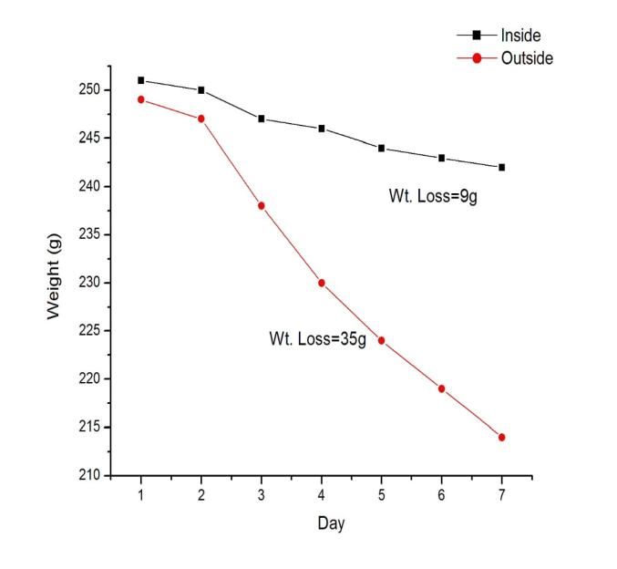
Design and Development of a Cooler used for Air Cooling and Refrigeration

         i. Aspen cooling pad
        ii. Cellulose pad (Honeycomsb pad)
 i. Aspen cooling pads
      Aspen cooling pads are made up of synthetic fiber and
   wood, and looks like a grass. Aspen cooling pads are cheap
   and economical, this is the reason Aspen cooling pads coolers
   are cheap but it require high maintenance and it is less durable
   material. Aspen pads are less effective than the cellulose pads.

                                                                                        Fig. 6 Refrigeration box
                                                                          D. Experimental Setup

                            Fig. 3 Aspen pad
ii.     Cellulose pads
         It is made up of cellulose material and also called
      honeycomb pads, it is very effective in cooling and require
      high maintenance or cleaning. This is high durable material
      and more effective than the aspen cooling pads. In desert air
      coolers cellulose pads are used because of their cooling
      potency of air in large scale.

                                                                          Fig. 7 Experimental cooler with loaded refrigeration box

                         Fig. 4 Honeycomb pad                                The rectangular refrigeration box is attached as shown.
                                                                          Capacity of the refrigeration box will depend on the size of
      B. Motor, Pump, Fan                                                 the cooler tank however, in the present work for further
                                                                          computations a mid-size cooler is considered and the capacity
         Other parts include the selection of motor driven exhaust
                                                                          of refrigerator box is taken as 30L. All surfaces of the box are
      fan to drive the flow of air into the room to be cooled. A pump
                                                                          in contact with tank water except the front face which is door
      is used for water carrying from tank of cooler to top
                                                                          of a refrigerator box.
      distribution systems, where it is distributed to the three
      different pads.
                                                                             Tank of cooler is insulated by rubber pad from outside to
                                                                          avoid any loss of heat. To analyze the performance of
                                                                          refrigerator, hot water with initial temperature as ambient is
                                                                          considered inside the refrigeration box.

                                                                                 V. EXPERIMENTAL VALIDATION AND
                                                                                     NUMERICAL COMPUTATION

                        Fig. 5 Fan, Motor, Pump                              To validate the mathematical model proposed in series of
                                                                          experiments were performed in controlled atmosphere inside
      C. Refrigeration box                                                a room in the climate of Raipur (Chhattisgarh), India. The
         The box we used in this project is made up of G.I. Sheet         experiment cooler has tank capacity of 90L is cubical shaped
      which is in rectangle shape, which is to be kept inside the         with the cellulose paper pad as evaporative media. An exhaust
      cooler tank for that purpose it has been fully insulated, so that   fan (100W) has been fixed in the front face to induce the hot
      we kept it inside the water. Inside the box we have fitted two      air coming into the cooler pad. A pump (40W) is placed into
      bulbs are fitted of 5W & 10W and also a sensor is fitted for        the tank of the cooler to allowing the flow of water from
      taking the reading of temperature inside the box. The box is        upside to downside into cooler pad. This cooler pad comes in
      having     the     sizes   (Length=30cm,        Breadth=35cm,       contact of air there will be transfer of heat and mass between
      Height=10cm).                                                       air and water as result of this both air and water gets cooled. In
                                                                          cooler’s tank this cooled water is
                                                                          stored. The proposed method is

                                                                                Published By:
        Retrieval Number: E6886018520/2020©BEIESP
                                                                                Blue Eyes Intelligence Engineering
        DOI:10.35940/ijrte.E6886.018520
                                                                      5195      & Sciences Publication
International Journal of Recent Technology and Engineering (IJRTE)
ISSN: 2277-3878, Volume-8 Issue-5, January 2020
to use stored cool tank water. A refrigeration box made of 15 24.3 23.8 22.4 22.5 25.4 25.6
mild steel plate is clamped inside the tank of the desert cooler 20 23.2 23.0 21.6 21.7 24.9 25.5
25 22.8 22.5 21.5 21.2 24.7 25.4
as shown in figure (6). To simulate the refrigeration load
30 22.6 22.2 20.6 20.9 24.8 25.3
electric bulbs (5W and 10W) is placed inside the refrigeration 35 21.8 22.0 20.5 20.8 24.6 25.3
box. Temperature sensors are fixed inside the box to measure 40 21.6 22.0 20.5 20.7 24.6 25.2
the transient temperatures of enclosure in the box. To measure 45 21.5 21.9 20.4 20.6 24.7 25.2
the temperature of tank water temperature sensor is placed 50 21.4 21.8 20.5 20.5 24.6 25.2
inside the tank of the cooler. Cooler was kept in a small room, e 2.44 3.17 1.90
r 0.98 0.97 0.96
having exit air duct. This duct is going out of the room to
Table-2 Theoretical and experimental temperature inside
provide stable conditions inside room. Air is coming into the
box, tank water and exit air with 10W Load
cooler from an open window opposite to the cooler. To
determine the humidity and temperature of inlet air RTD
( Ta 31.7 o C , 42% , va 1.5m / s )
sensors which have 0.2% to 1% accuracy and digital Time Box Tank water Exit air
(m) temperature temperature temperature
hygrometer with 5% accuracy are fixed at three different
(oC) (oC) (oC)
points inside room. The temperature of exit air was measured Ex. Th. Ex. Th. Ex. Th.
by two temperature sensors kept in exit air duct. Velocity of 0 31.4 31.4 32.6 32.6 31.8 31.8
inlet air was measured by electronic type digital anemometer 5 30.5 30.9 27.9 28.3 28.1 27.5
with 5% accuracy. The incident air velocity on pad is used for 10 29.3 28.3 25.5 25.7 26.9 27.2
computing convective heat transfer coefficient hc between 15 27.2 26.9 24.0 24.3 26.7 27.0
20 25.8 26.0 23.8 23.4 26.5 26.9
pad material and air. Two RTD temperature sensors are kept 25 25.5 25.5 23.4 22.9 26.4 26.8
inside refrigeration box to measure the temperature of 30 25.3 25.2 23.0 22.6 26.3 26.7
enclosure. Cooler is enclosed by evaporating pad of 35 25.0 25.0 22.9 22.5 26.4 26.7
dimensions 0.50 0.45 0.10 m3 . Front side is provided 40 24.8 25.1 22.7 22.4 26.3 26.7
45 24.5 24.9 22.6 22.3 26.3 26.7
with an exit air duct with a fan (Crompton, 1400 RPM), 50 24.5 24.8 22.7 22.3 26.3 26.7
connected to draw in outside air (warm air) into the cooler e 2.10 2.06 1.72
pad. A pump (Bajaj, 40W) is placed inside the cooler tank r 0.98 0.99 0.98
(0.74mx0.74mx0.17m) to feed water from tank into the cooler Graphical representation of theoritical and experimental
pads. The pad is made of honeycomb cellulose paper with an box temperature
evaporating surface of 370 m2 m3 (curtsey manufacturer)
and convective heat transfer coefficient hc given by [10],
le 0.12
Nu 0.10( ) Re0.8 Pr1/3
l
vo
le (Chartersticlength)
Ap
Here, le is characteristic length, l is thickness of pad which
is equal to x0 , ratio vo is the ratio between volume occupied
Ap
3 2
by pad material and total wetted surface area ( m / m )
Rate of mass flow of flowing water in pads is computed by
measuring time taken. Tank water temperature, exit air
temperature and preservation temperature (inside box) with
load is recorded at the time interval of 5mins. Cooler is
Graph 1. Relationship between theoretical and
allowed to run for 5mins only through pump to keep pads
experimental temperature inside box w.r.t. time for 5W
uniformly wet before starting the experiment. Computed and
Load
recorded preservation temperature, tank water temperature
and exit air temperature at two different loads 5W and 10W
are shown in tables 1-2 and relationship between theoretical
and experimental temperature inside box w.r.t. time are
shown in graph 1-2.
Table-1 Theoretical and experimental temperature inside
box, tank water and exit air with 5W Load
( Ta 30.6o C , 38% , va 1.5m / s )
Time Box Tank water Exit air
(m) temperature temperature temperature
(oC) (oC) (oC)
Ex. Th. Ex. Th. Ex. Th.
0 29.8 29.8 30.5 30.5 30.6 30.6
5 28.4 27.6 27.5 26.3 26.2 26.2
10 26.5 25.2 24.4 23.9 25.7 25.8
Published By:
Retrieval Number: E6886018520/2020©BEIESP Blue Eyes Intelligence Engineering
DOI:10.35940/ijrte.E6886.018520 5196 & Sciences Publication
Design and Development of a Cooler used for Air Cooling and Refrigeration

                                                                                     244g                      224g
                                                                      28-04-2019

                                                                                     243g                      219g

                                                                      29-04-2019

                                                                                     242g                      214g
                                                                      30-04-2019

                                                                   Graphical representation of weight loss between inside
                                                                   and outside apples

    Graph 2. Relationship between theoretical and
experimental temperature inside box w.r.t. time for 10W
                        Load

       VI. PERFORMANCE OF LOADED BOX
   Refrigeration box is loaded with apples and the freshness of
the stuff stored is observed daily. To save the electric power
the fan of the cooler is kept off during night time and the pump
of the cooler is kept on the water stored in the tank water is
pumped in to the top and circulated through cooler pad. The
water and air get cooled naturally by coming in contact with
surrounding air. The fan of cooler is kept on for all the day
during night it is kept off. The weight of the fruits stored is
measured daily and the loss in weight is determined. The
photographs of the stored items are shown in the Table 3 and
the graph showing the weight loss in Graph 3
   To determine the actual performance of the refrigeration                 Graph 3. Weight loss by apple w.r.t. days
box placed in the cooler tank experiments were performed           Set of experiments were perform to determine the freshness of
with loaded refrigeration box. In the experiment box is loaded     stored products upside clay pot as proposed by author.
with apples (fruits) and parallel to this, same quantity of        Experiment was performed by loading pot with apples. In
apples is kept outside in the room. The daily weight loss by       orders the product stored to assistant the quality of the product
the fruits is measured and the photographs of the fruits stored    preserved in the pot .The present used products is compared
are taken. The experiment was performed continuously for a         with those kept outside in the same environment.
week.

    Table-3 Determination of daily weight loss by apple            Freshness of apples is shown in table 3 and daily weight loss is
                                                                   shown in graph 3.
                 Weight of Apple             Weight of
    Dates
                   (inside box)            Apple(outside)                      VII. RESULTS AND DISCUSSION
                251g                     249g
                                                                      It is seen from Table 1-2 and Graph 1-2, that as a result of
 24-04-2019
                                                                   evaporation of water in pads, both temperature of tank water
                                                                   and exit air decreases and consequently the space inside box
                250g                     247g                      is also cooled this gives result of transfer of heat from box to
 25-04-2019                                                        tank water. Rate of cooling is more in the beginning and
                                                                   temperature inside the box becomes almost constant within 30
                                                                   to 35mins. Degree of cooling depends on the rate of cooling
                247g                     238g                      of tank water due to evaporation in cooling pads. It is
 26-04-2019                                                        influenced by the climatic parameters (outside temperature,
                                                                   relative humidity) as well as heat transfer coefficient between
                                                                   pad material and air. Experimental and theoretical values are
                246g                     230g                      nearly close to 1.
 27-04-2019

                                                                          Published By:
  Retrieval Number: E6886018520/2020©BEIESP
                                                                          Blue Eyes Intelligence Engineering
  DOI:10.35940/ijrte.E6886.018520
                                                               5197       & Sciences Publication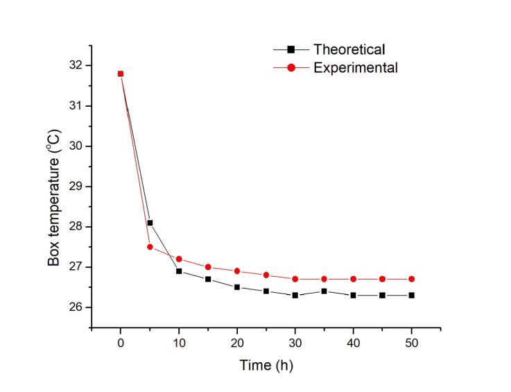
International Journal of Recent Technology and Engineering (IJRTE)
                                                                               ISSN: 2277-3878, Volume-8 Issue-5, January 2020

   From Table 3 it is seen that the weight loss from apples kept             8. Singh SP, Tulsidasani TR, Swahney RL, Sodha MS, “Recent research
                                                                                 on IEC Part-I: Optimization of the COP” (1997).
outside is more in comparison to the apples stored in the                    9. Singh SP, Tulsidasani TR, Swahney RL, Sodha MS, “Recent research
refrigeration box. The weight loss in seven days is about 35g                    on IEC Part-II: Thermal performance of a non-conditioned building
when kept outside where as weight loss is only 9g when stored                    coupled with an IEC” (1997).
inside box. Graph 3 shows temperature of inside apples is                    10. Singh SP, Tulsidasani TR, Swahney RL, Sodha MS, “Recent research
                                                                                 on IEC Part-III: Optimization of the cooling potential of a room-coupled
decreasing and the outside apples temperature increasing                         IEC” (1998).
continuously. Apples of inside the refrigeration box are in                  11. Singh SP, Tulsidasani TR, Swahney RL, Sodha MS, “Recent research
good condition in compare of outside apples.                                     on IEC Part-IV: Effect of recirculation on cooling of a room coupled to
                                                                                 an IEC” (1997).
                                                                             12. Singh SP, Tulsidasani TR, Swahney RL, Sodha MS, “Recent research
                      VIII. CONCLUSION                                           on IEC Part-V: Relative thermal performance of buildings coupled to
                                                                                 direct and indirect evaporative cooler” (1997).
   In present work a model of a dual purpose cooler utilized                 13. Singh SP, Tulsidasani TR, Swahney RL, Sodha MS, “Recent research
for air conditioning as well as refrigeration has been prepared.                 on IEC Part-VI: Evolution of design pattern for IEC” (1999).
This air cooler can be used to store fruit / vegetables etc. In              14. Alonso JS, Martinez FR, Gomez EV, Plasencia MA, ”Simulation model
                                                                                 of an IEC”, Energy and Buildings, (1998).
present work thermal performance of the cooler has been                      15. Camargo JR and Ebinuma CD, “A mathematical model for direct and
determined and following conclusions have been drawn:                            indirect evaporative cooling AC systems”, Thermal Engineering and
1) Mathematically of the proposed cooler utilized for air                        Sciences, Caxambu, Brazil, (2002).
                                                                             16. Riangvilaikul B and Kumar S, “An experimental study of a novel dew
     cooling and refrigeration has been developed by writing                     point evaporative cooling system”, Energy Build, 637-644 (2010).
     equations of energy balance for the various parts.
2) The mathematical model has been validated by                                                     AUTHORS PROFILE
     conducting a series of experiments under a small room in
                                                                                               Bhupendra Sahare is completed his BE degree in
     an experimental test rig, to simulate the refrigeration load                              Mechanical Engineering from MATS University - Raipur
     electric bulbs (5W and 10W) has fixed inside the                                          and pursuing his M. Tech degree in Thermal Engineering
     refrigeration box. It is seen that the experimental value                                 from GEC Jagdalpur, Chhattisgarh, India.
     are reasonably close to theoretical value, the value of “e”
     comes in between 1.72 to 2.68 and coefficient of
     correlation (r) value is in between 0.91 to 0.99 and it’s
                                                                                               Chhavikant Sahu is working as Assistant Professor in
     close to 1.
                                                                                               the Department of Mechanical Engineering, Government
3) In this experiment it is seen that the weight loss from                                     Engineering College Jagdalpur, Chhattisgarh, India.
     apples kept outside is more in comparison to the apple
     stored in the inside of refrigeration box, the temperature
     of apples is decreasing when it kept inside the box and the
     temperature of apples in increasing when it kept outside.
     Apple are in good condition in compare of outside
     apples, the weight of inside are decreasing less than in
     compare of outside.

                      IX. FUTURE SCOPE
   In this project, perception of room cooling and
refrigeration box was made for storage of biodegradable
items especially foodstuffs. Optimization of operating
parameters may be used to build a useful and cost effective
system.

REFERENCES
1. Watt JR, “Evaporative Air Conditioning”, The Industrial Press, New
   York, 1986.
2. Mathur ML and Jain BP, “Performance of a portable cooler: desert
   cooler”, Journal of Institute of Engineers (India), 241-245 (1979).
3. Mathur ML and Jain BP, “Experimental study of performance of
   portable air washer type air cooler”, Journal of Institute of Engineers
   (India), 38-40 (1982).
4. Singh SP, Sawhney RL, Bansal NK, Sodha MS, “Sizing of an
   evaporative cooler for thermal comfort inside a room”, Housiong
   Science, 141-148 (1987).
5. Singh SP, Sawhney RL, Bansal NK, Sodha MS, “Optimization of an
   evaporative cooler for space cooling”, Housing Science, 225-231
   (1987)’
6. Dowdy JR and Karabash NS, “Experimental determination of heat and
   mass transfer coefficients in rigid impregnated cellulose evaporative
   media”, ASHRAE Transactions, 382-395 (1987).
7. Sodha MS, Singh SP, Sawhney RL, “Evaluation of design patterns for
   direct evaporative coolers”, Building and Environment,278-291 (1995).

                                                                                     Published By:
    Retrieval Number: E6886018520/2020©BEIESP                                        Blue Eyes Intelligence Engineering
    DOI:10.35940/ijrte.E6886.018520                                      5198        & Sciences Publication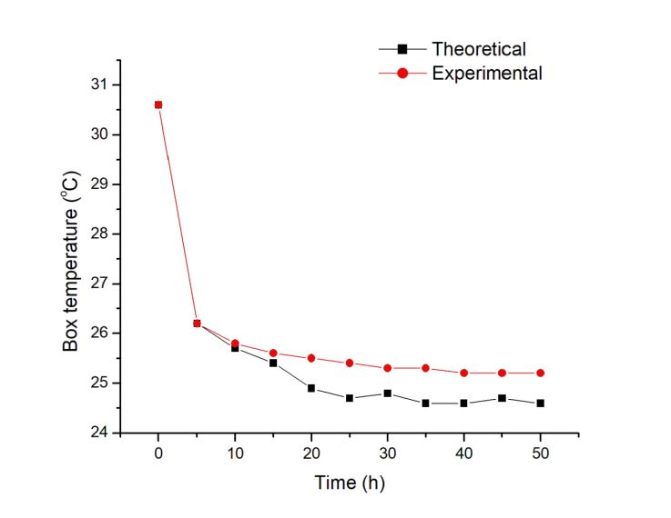
You can also read