Design of a filtering car air purifier - IOP Conference Series: Earth and Environmental Science - IOPscience
←
→
Page content transcription
If your browser does not render page correctly, please read the page content below

IOP Conference Series: Earth and Environmental Science

PAPER • OPEN ACCESS

Design of a filtering car air purifier
To cite this article: Xue Dong 2021 IOP Conf. Ser.: Earth Environ. Sci. 632 052095

View the article online for updates and enhancements.

                               This content was downloaded from IP address 46.4.80.155 on 10/10/2021 at 22:10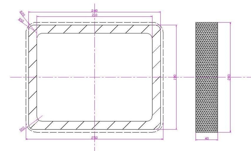
2020 Asia Conference on Geological Research and Environmental Technology                 IOP Publishing
IOP Conf. Series: Earth and Environmental Science 632 (2021) 052095  doi:10.1088/1755-1315/632/5/052095

Design of a filtering car air purifier

                     Xue Dong*
                     Department of Mechanical and Electrical Engineering, Shandong Transport
                     Vocational College, Weifang, 261000, Shandong, China
                     *
                         Corresponding author: dongxue966@sdjtzyxy.com

                     Abstract. Aiming at serious air pollution in the passenger car, in this paper, a filtering c
                     ar air purifier is designed. This paper mainly consists of selection of the fan, design of
                     the filter, design of the shell, processing of all parts, assembly of the complete machin
                     e, usage, operation process, and usage. Finally, through the detection of the filtering ca
                     r air purifier designed in this paper, the test shows that this filtering air purifier can rem
                     ove harmful substances, such as formaldehyde, in the car.

1. Introduction
With the popularization of cars, air pollution in the car attracts more and more attention. Pollutants in t
he car are mainly produced by the release of harmful substances in equipment and decorating materials
 in the car, and these materials in the car have large quantity of toxic gases, including benzene, formald
ehyde, xylene, etc [1]. The concentration of toxic gases in new cars leave factory is excessively high, an
d the volatilization time can last more than 6 months. These harmful substances can unconsciously poi
son people who will then have symptoms such as headaches, nausea, fatigue, coughing, sneezing, or ev
en cause serious diseases such as leukemia. In addition to materials in the passenger car, the leakage, e
vaporation of fuel, lubricants, and refrigerants, and mildew and nicotine produced by the air-conditioni
ng system are the main sources of air pollution in the car. At current, there have been many methods o
n the market to purify the air in the car, such as, fragrance deodorants and activated carbon bags, but m
ost of them have some hidden safety hazards or low cost performance. Therefore, it is necessary to acti
vely develop a set of air quality improvement devices in the passenger car so as to improve the air envi
ronment quality. After studying the purification methods, this paper designs and develops an efficient,
low-powered passenger car air purifier with no side effects, so as to provide the drivers and passengers
 with comfortable and safe riding environment.

2. Product design
Now, there are many types of car air purifier sold on the market, and according to the principles, there
are mainly four types, namely, filtering car air purifier, dust-accumulated car air purifier, ozone car air
purifier, and negative oxygen ion car air purifier [2]. The air purifier designed in this paper is a filtering
car air purifier. In general, the filtering car air purifier is composed by a shell, a fan (air supply system),
 and filter (purification system) [3]. In terms of its principle, it mainly uses the fan for forced ventilation,
 and adopts porous filter materials, such as non-woven fabrics, fibers, and foam, to adsorb and decomp
ose suspended particles and harmful gases in the air, thus purifying the air in the car. The structure dia
gram of the air purifier is shown in Figure 1.

              Content from this work may be used under the terms of the Creative Commons Attribution 3.0 licence. Any further distribution
              of this work must maintain attribution to the author(s) and the title of the work, journal citation and DOI.
Published under licence by IOP Publishing Ltd                          1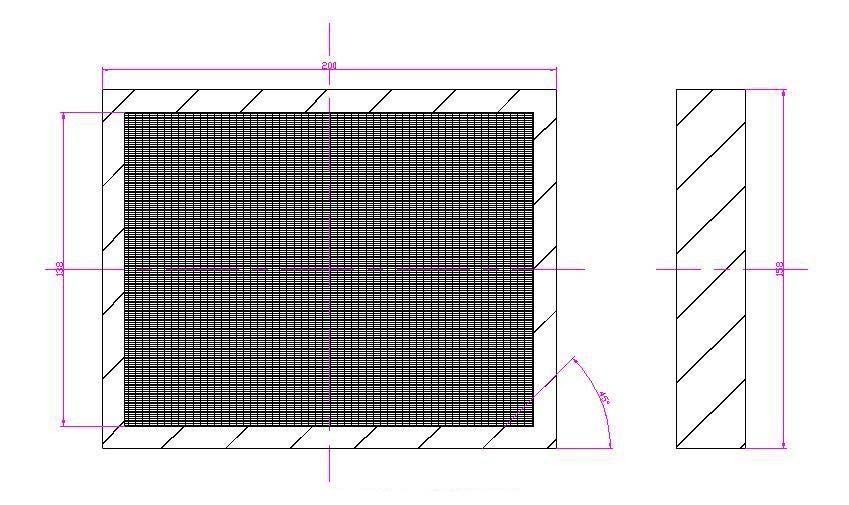
2020 Asia Conference on Geological Research and Environmental Technology                 IOP Publishing
IOP Conf. Series: Earth and Environmental Science 632 (2021) 052095  doi:10.1088/1755-1315/632/5/052095

                            Figure 1. Structure diagram of the air purifier.
  1-upper shell, 2-lower shell, 3-prefilter, 4-primary filter, 5-new high performance adsorbent,6- post
                                  filter, 7- protective screening, 8- fan.

2.1. Selection of the fan
The selection of the fan shall take the wind speed, wind pressure and resistance into account. There is
not too much pollution gases produced in the general passenger car per unit time. With comprehensive
consideration of the volume and effect of the filter designed, this design will adopt the German EBM
external-rotor axial flow fan with ultra-high performance. This fan has a rated voltage of 12V, 24V and
48V, and it is featured by compact structure, low noise and good heat dissipation effect. Integrating
external electronic equipment, it can efficiently adjust the air flow through precise open-loop or closed-
loop control, and at the same time, it has signal alarm, Lin / PWM output, and open-loop control and
bus interface depending on temperature or flow. The schematic diagram of the fan is shown in Figure 2:

          Figure 2. German EBM external-rotor axial flow fan with ultra-high performance.

                                                     2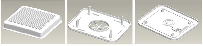
2020 Asia Conference on Geological Research and Environmental Technology                 IOP Publishing
IOP Conf. Series: Earth and Environmental Science 632 (2021) 052095  doi:10.1088/1755-1315/632/5/052095

2.2. Design of the filter
The filtering effect of the filter is not only related to the wind speed, wind pressure, and resistance, but
also directly related to the material and area selected [3]. The selection shall mainly consider adsorptio
n capacity, residence time, service life and adsorb ability.

2.2.1. Selection of filter layer materials. The adsorption media designed and selected in this paper
mainly take various purification materials with different adsorption functions, such as granular active
carbon and activated alumina, as the base materials.
    The high efficiency filter is filled with PIA and N4G1, and the chemical filter is filled with PCM. P
IA is mainly composed of spherical activated alumina and potassium permanganate, and the main gase
s it can remove are H2S, NO, formaldehyde, ethylene, organic acids, amines, etc .; N4G1 is mainly co
mposed of cylindrical broad-spectrum activated carbon, and the main gases it can remove are hydrogen
 compounds, benzene, acetone, chlorine, ozone, smoking odor, garbage odor, etc .; PCM is a compoun
d of 50% PIA and 50% N4G1, and the main gases it can remove are formaldehyde, hydrogen sulfide,
mercaptans, acetaldehyde, acetic acid, nitrogen oxides, ozone, VOCs, etc.

2.2.2. Parameter design of the filter. The filter is composed by a primary filter and a high efficiency fi
lter. The primary filter is a layer of rectangular foam to be installed with the high efficiency filter whic
h is installed at the air inlet. Both are designed as cuboids. Considering the service life, specific structu
re and site conditions, etc. of the filter, the parameters of the filter are designed as follows: The cuboid
has a length of 200mm, a width of 158mm and a height of 30mm. Considering the dust removal effect,
 the interior is made into folds to increase the contact area of the catalyst with pollutants. The structure
diagram is shown in Figure 3:

                              Figure 3. Primary and high efficiency filters.

    The chemical compound filter is composed by a metal filter (three layers), a chemical filter, and a p
ost filter.
    Considering the size of the fan selected, the internal structure of the reactor must ensure the full con
tact of the catalyst with pollutants, and the flow rate of the polluted air flow through the purifier. The c

                                                      3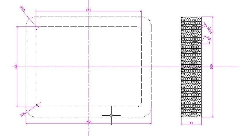
2020 Asia Conference on Geological Research and Environmental Technology                 IOP Publishing
IOP Conf. Series: Earth and Environmental Science 632 (2021) 052095  doi:10.1088/1755-1315/632/5/052095

hemical compound filter is initially designed as a rectangular frame with the outer diameter of 82 cm, t
he width of 73 cm, the height is 40mm, and the thickness is 15mm. The structure diagram is shown in
Figure 4.

                                     Figure 4. Chemical compound filter.

2.3. Design of the shell

2.3.1. Selection of shell materials. In order to reduce weight and costs, the shell material adopts ABS p
lastic with high strength, good toughness, and low price [4].

2.3.2. Parameter design of the shell. The space in a family car is about 2-3m³, and due to the mall spac
e, the purifier cannot be too large. Considering that it is necessary to ensure the full contact of the catal
yst with pollutants, and the flow rate of the polluted air flow through the purifier, the shell is designed t
o be composed by an upper cover, a middle shell, and a base. The size of the upper cover is 205mm * 1
63 * 40mm, and the size of the middle shell and the base is 250mm * 200mm * 40mm, with the wall th
ickness of 8mm. The upper cover is provided with a vent which allows the polluted air enter the reactio
n chamber of the air purifier under the driving effects of the fan. The base is used to install the fan and
chemical compound filter, and there are protruded grooves on it to fix the chemical filter. The structure
 diagram of the upper cover, middle shell and base is shown in Figure 5:

                   (a) upper shell                (b) lower shell                (c) base
                                Figure 5. Schematic diagram of the shell.

                                                      4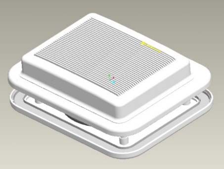
2020 Asia Conference on Geological Research and Environmental Technology                 IOP Publishing
IOP Conf. Series: Earth and Environmental Science 632 (2021) 052095  doi:10.1088/1755-1315/632/5/052095

2.4. Design of other parts

2.4.1. Protective screening. In order to protect the high efficiency filter from abrasion and prolong its l
ife, a layer of protective screening is installed to the outer and inner sides of the high efficiency filter.
The inner screening height is 44mm and the outer screening height is 46mm, as shown in Figure 6:

                        Figure 6. Schematic diagram of the protective screening.

2.4.2. Anti-slip mat. The anti-slip mat is installed at the bottom of the lower shell. Its material is heat-r
esistant rubber, and its main function is to fix the purifier firmly to the back of the seat, so as to preven
t friction for bump between the purifier and the seat. The parts drawing of the anti-slip mat is shown in
 Figure 7:

                              Figure 7. Schematic diagram of anti-slip mat.

                                                      5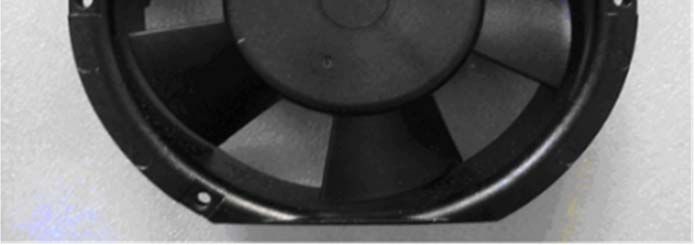
2020 Asia Conference on Geological Research and Environmental Technology                 IOP Publishing
IOP Conf. Series: Earth and Environmental Science 632 (2021) 052095  doi:10.1088/1755-1315/632/5/052095

3. Assembly of the purifier
After processing of dimension parameters and selected materials of all parts, the purifier is assembled
according to the assembly steps. The process is as follows:
    (1) Fix the fan in the center of the base, and connect the fan to the power adapter connector with a
wire.
    (2) Put the chemical compound filter into the base, and note to keep the end with the power socket a
ligned with the end of the filter with a gap bench to prevent air leakage.
    (3) Install the upper cover, primary and high efficiency filters, middle shell, chemical compound fil
ter, and rear seat with fan according to the direction of gas flow in order as shown in Figure 8:

                                      Figure 8. Installation drawing.

   The three-dimensional and physical map are shown in Figure 9:

                          (a) Three-dimensional map             (b) Physical map
                   Figure 9. Three-dimensional and physical map of the air purifier.

4. Usage and operation process

4.1. Usage
(1) Tie the built-in belts to the back of the seat.
    (2) Connect one end of the cable of the cigarette lighter to the purifier, and the other end to the car l
ighter socket. The machine starts to work, and disconnect the power when not in use.

4.2. Operation process of the air purifier
(1) The polluted air is absorbed into the air purifier through the strong negative pressure generated by t
he fan, and suspended solids such as inhalable particulate matter and dust with larger particle size are r
emoved by the primary filter.

                                                      6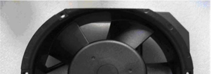
2020 Asia Conference on Geological Research and Environmental Technology                 IOP Publishing
IOP Conf. Series: Earth and Environmental Science 632 (2021) 052095  doi:10.1088/1755-1315/632/5/052095

    (2) The air filtered by the primary filter passes through the HEPA filter to remove dust mites, dust
(bacteria clumps), and fine dust particles larger than 0.3 micrometers, to complete the high-efficiency f
iltering;
    (3) The air highly filtered will pass through the chemical compound filter which is composed by the
 metal filter (three layers), the chemical filter, and the post filter. The metal filter can remove the charg
ed ions in the air, and completely removes the charged ions floating in the air; The chemical filter is co
mposed of composite adsorption and decomposition materials with no toxic and side effects, and mainl
y removes odors and toxic organic volatiles produced by decorative materials, breathing, smoke, and c
hemicals in the air; The post filter can block particles that may be produced in the filtering process so a
s to ensure the freshness of the air entering the car through the purifier. Finally, clean air is discharged
from the air outlet.

5. Detection

5.1. Detection methods
Currently, the method that can evaluate the purification efficiency of air purifiers more objectively is c
lean air delivery rate (CADR) which is proposed with reference to American standards. As a performa
nce index which is related to the use feature of air purifiers and can reflect the purifying capacity, it is
not only applicable to evaluate the ability of air purifiers to remove suspended particle, but also applica
ble to evaluate the ability to remove other air pollutants [9]. Due to the restrictions, this paper just tests
 formaldehyde.

5.2. Detection of closed testing device and test steps
Currently, the method that can evaluate the purification efficiency of air purifiers more objectively is c
lean air delivery rate (CADR) [5].
    (1) Evaluation device and conditions
    The volume of the closed testing chamber is 1m³, and the chamber is equipped with a circulating fa
n. The temperature in the testing chamber is maintained at (21 + 2.5) degrees, and the relative humidity
 is (50 + 5) %.
    (2) Test steps
    Place the air purifier to be tested in the middle of the testing chamber and adjust the air purifier to t
he operation state of the test. The detection is normal. Inject formaldehyde gas (concentration: 20mg /
m3) into the testing chamber at a flow rate of 5L / min (formaldehyde diluent) for 10min. Test the form
aldehyde concentration in the testing chamber with air purifier turned on and off within 140 minutes. T
he sampling port flow rate is 0.5L / min, and the sampling time is 20min.

                     Figure 10. Purification effect of purifier on formaldehyde gas.

                                                       7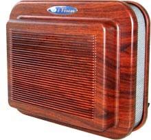
2020 Asia Conference on Geological Research and Environmental Technology                 IOP Publishing
IOP Conf. Series: Earth and Environmental Science 632 (2021) 052095  doi:10.1088/1755-1315/632/5/052095

5.3. Test results
It can be seen from Figure 10 that the purification effect of the air purifier is significant. For formaldeh
yde gas with an initial concentration of 1.2 mg / m3, the removal efficiency of formaldehyde is over 9
0% after the air purifier is operated for 140 minutes.

6. Conclusions
Aiming at the current situation of air pollution in the passenger car, this paper designs a filtering car air
 purifier. Based on the test analysis, the air purifier designed in this paper can effectively improve harm
ful substances, such as formaldehyde, in the car. The improvement of air quality in the car is a long-ter
m work, and the use of air purifiers for the improvement is only a small measure. To make sure people
 enjoy the pleasure of driving and not harmed by air pollution, the relevant government departments, e
nterprises for car research and development, and automotive interiors materials enterprises must reach
a consensus and do a good job of preventing pollution in the car.

Acknowledgements
2019 Shandong province vocational education teaching reform research project. Project no: 2019535.
   2020 Shandong Province Key Topics of Employee and Vocational Education. Project no: 2020-310.
   2020 Shandong Province Vocational Education Research Project no: 0SVE081

References
[1] Summary of mainstream technologies of car air purifiers and the development trend [J]. Tang Xi
        ngping. Green Environment Protection Building Materials. 2018 (04): 29
[2] Li Fan, Liu Kai, Wang Quanjie et al. Design and research of car air purifier. Utomobile Technol
        ogy 2018, (09): 65-68
[3] Meng Fanfang, Xu Kai, Wang Peiqin, et al. Appearance and structure design of car air purifier h
        ina Southern Agricultural Machinery 2018,49 (16): 97-98
[4] Sun Zhengyang, Han Quanquan, Wan Hongqiang, et al. Development of a filtering car air purifi
        er. Electronics World 2019, (19): 91-92
[5] Zhao Guifang, Photocatalytic treatment of indoor formaldehyde and design of air purifiers [D] D
        alian University of Technology, 2007: 42-44.

                                                      8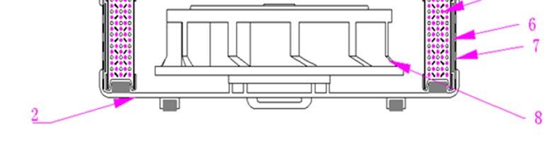
You can also read


