OPERATING & INSTRUCTION MANUAL
←
→
Page content transcription
If your browser does not render page correctly, please read the page content below
OPERATING & INSTRUCTION MANUAL
Renew™ Air Treatment Solution | Version 1.0

www.luminator.com
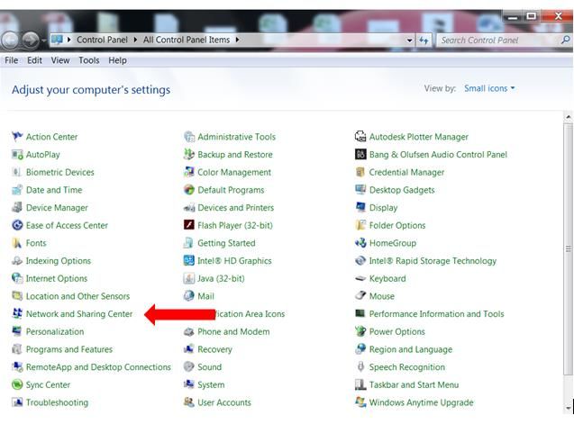
TABLE OF CONTENTS
1      INTRODUCTION.......................................................................................................................................................3
 1.1    Overview ............................................................................................................................................................ 3
 1.2    Disclaimer ......................................................................................................................................................... 3
 1.3    Warranty, Service and Support Information .................................................................................................... 3
 1.4    Safety Notes...................................................................................................................................................... 3
 1.5    System Components and Accessories ........................................................................................................... 3
2 System Atomizer .....................................................................................................................................................4
 2.1    Introduction ....................................................................................................................................................... 4
 2.2    Power................................................................................................................................................................. 4
 2.3    Mounting ........................................................................................................................................................... 4
 2.4    Mounting Illustrations ...................................................................................................................................... 4
 2.5    Connections ...................................................................................................................................................... 5
3 System Controller ....................................................................................................................................................6
 3.1    Introduction ....................................................................................................................................................... 6
 3.2    Power................................................................................................................................................................. 6
 3.3    Mounting ........................................................................................................................................................... 6
 3.4    Connections ...................................................................................................................................................... 6
 3.5    Configuration Settings...................................................................................................................................... 8
4 System Sensor ........................................................................................................................................................9
 4.1       Introduction ....................................................................................................................................................... 9
 4.2       Power................................................................................................................................................................. 9
 4.3       Mounting ........................................................................................................................................................... 9
 4.4       Connections ...................................................................................................................................................... 9
5 Initial System Setup...............................................................................................................................................10
 5.1    Install the Atomizer......................................................................................................................................... 10
 5.2    Install the Controller ....................................................................................................................................... 10
 5.3    Install the Sensor ............................................................................................................................................ 10
 5.4    Activate the Atomizer ..................................................................................................................................... 10
 5.5    Activate the Controller .................................................................................................................................... 11
6 Renew System Application ....................................................................................................................................12
 6.1     Introduction ..................................................................................................................................................... 12
 6.2     Accessing the Application.............................................................................................................................. 13
 6.3     Controller Status ............................................................................................................................................. 13
 6.4     Controller Configuration ................................................................................................................................. 14
 6.5     Controller Software Upgrade ......................................................................................................................... 15
 6.6     Controller Date and Time Settings................................................................................................................. 16
APPENDIX ...................................................................................................................................................................17
    Configure a Static IP Address ........................................................................................................................................ 17

Copyright 2020 Luminator Technology Group, Inc.

The information contained in this document is proprietary to Luminator Technology Group, Inc., and shall not be used or reproduced for any purpose
without prior written consent.

www.luminator.com                                                                                                                                                       Page 2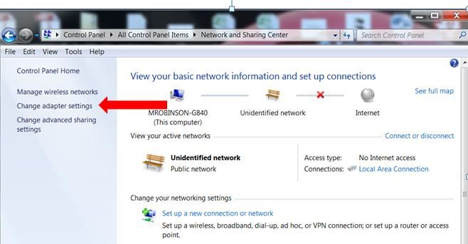
1 INTRODUCTION
1.1 OVERVIEW
This version of Luminator Technology Group’s Renew™ Air Treatment System is manufactured and designed
for installation and use in transit, rail and vehicle applications.
This guide has basic product information such as mounting information, connections, and startup procedures
for the system – including the Atomizer, Controller and Sensor.
1.2 DISCLAIMER
The information and specifications contained in this guide are subject to change without notice.
1.3 WARRANTY, SERVICE AND SUPPORT INFORMATION
For warranty, service and additional information including technical support, please visit: www.luminator.com
or contact technical support by email: support.na@luminator.com.
1.4 SAFETY NOTES
Do not submerge any components
Always disconnect components from power before manual cleaning
Do not operate the Atomizer if the housing, fluid tank, or cables appear damaged
In the event of a serious operating problem, stop using immediately
The system is designed for use only with Grignard PURE™
o Grignard PURE should not be diluted - do not add anything to the fluid
o Do not drink the fluid
o Avoid direct contact with skin or eyes
Only connect electrical components to a grounded and protected circuit
1.5 SYSTEM COMPONENTS AND ACCESSORIES
Operating and Instruction Manual (this guide)
Renew Atomizer
Renew Controller
Renew Sensor
Atomizer Power Cord
Remote Reservoir
Sensor to Controller Cable
Controller to Atomizer Cable
www.luminator.com Page 3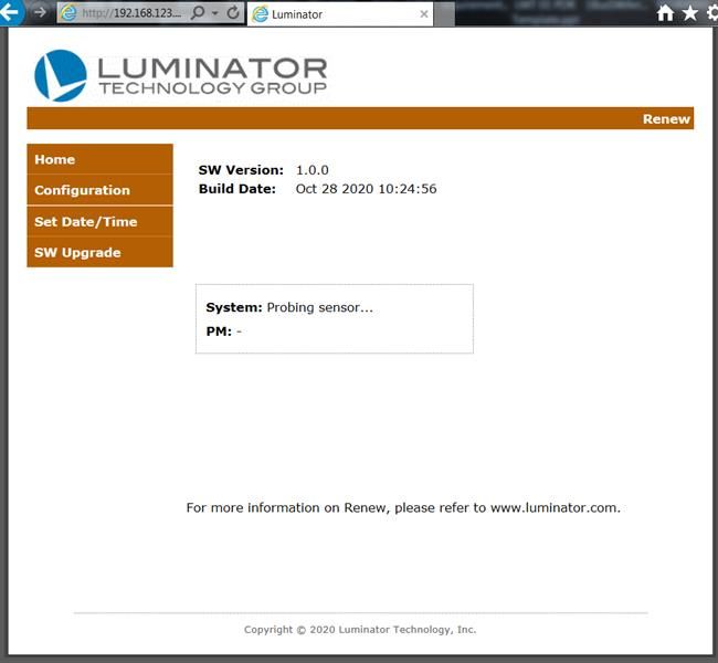
2         SYSTEM ATOMIZER
2.1 INTRODUCTION
       The Renew System Atomizer includes a fluid pump, air pump, heating element, power supply, and
       microcontroller. The Atomizer is designed to disperse Grignard Pure and is designed to be controlled
       autonomously using the Renew Controller and Renew Sensor.

2.2 POWER
       This product is designed to operate from a 120VAC power source.
       NOTE: THE ATOMIZER MAXIMUM POWER DRAW IS 365 WATTS @ 120VAC

2.3 MOUNTING
       NOTE: BEFORE MOUNTING THIS PRODUCT, REFER TO THE SAFETY NOTES.

    1. The Atomizer can mount to a side wall of a structure or bolted to a platform (for example luggage rack in a
       train/bus). ¼” -20 bolts are recommended fasteners.
    2. The Atomizer has been designed to allow for remote mounting directly into an HVAC plenum or duct to
       maximize dispersion characteristics of Grignard Pure in large spaces.
    3. For best results, HVAC plenum or duct mounting should be located after the HVAC filter, blower fan, and
       evaporator coil.
    4. When mounting outside of the HVAC duct or plenum but still using the HVAC system as a dispersion
       mechanism, a 4” O.D. duct (not included) can be attached to the outlet of the machine and piped to the HVAC
       duct or plenum.

       NOTE: IF PLENUM PRESSURE IS TOO HIGH FOR THE ATOMIZER FAN, THE ATOMIZER CAN BE CONNECTED
       IN BYPASS MODE. BYPASS MODE UTILIZES A 4” DUCT ATTACHED FROM THE HVAC PLENUM TO THE INLET
       OF THE ATOMIZER AND A SECOND 4” DUCT OF EQUAL LENGTH ATTACHED TO THE OUTLET OF THE
       ATOMIZER BACK TO THE HVAC PLENUM.

2.4 MOUNTING ILLUSTRATIONS
                                            FIGURE 1: ANCHOR TO SURFACE

      Anchor to surface with
          ¼” -20 bolts

www.luminator.com                                                                                         Page 4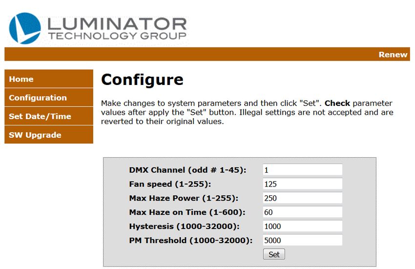
FIGURE 2: BRACKET POSITION FOR FLOOR MOUNT
FIGURE 3: BRACKET POSITION FOR WALL MOUNT
2.5 CONNECTIONS
5 pin XLR Pin Receptacle connector
Used to control the Atomizer
Half duplex RS485
DMX Protocol
RDM protocol (Future)
Data +/-, GND
3 Pin Twist Lock Receptacle connector
Used to power the Atomizer
120VAC
www.luminator.com Page 5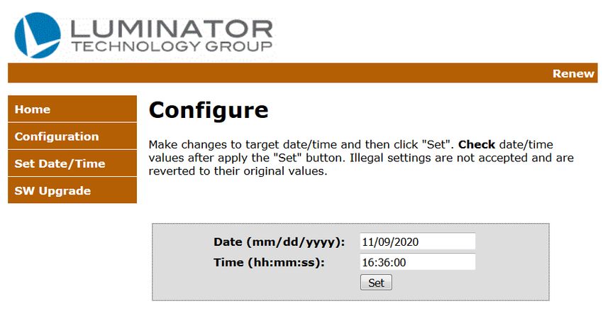
3 SYSTEM CONTROLLER
3.1 INTRODUCTION
The Renew System Controller obtains data from the Sensor, to monitor levels of Grignard Pure in the air and
continuously adapts the amount of product to be dispersied by the Atomizer. This enables the system to
maintain the pre-determined effective concentration at all times.
The Controller monitors a PM2.5 laser difraction particle Sensor, once per second.
As with any closed loop control, there are several configuration settings that can be changed to maximize the
performance of the control loop. For example, a small volume area with little fresh air replenishment will detect
the presence of atomized solution much faster than a large volume are with high fresh air replenishment rates.
The initial settings for the small volume space would be lower than for the large volume space.
This knowledge of the environment and preset parameters is known as “feed-forward” or “open loop” control.
These feed-forward values can account for the major portion of the controller output while allowing the
automatic adaptive feedback control to account for the smaller deviations above the desired set point.
3.2 POWER
This product is designed to operate from a 120VAC power source.
NOTE: THE CONTROLLER MAXIMUM POWER DRAW IS LESS THAN 6 WATTS
3.3 MOUNTING
NOTE: BEFORE MOUNTING THIS PRODUCT, REFER TO THE SAFETY NOTES.
The controller can be mounted virtually anywhere within the limits of the sensor cable length and the
Atomizer cable length..
The controller provides an Ethernet access port for configuration and system status which makes it
beneficial to mount it in a location where a laptop can be connected directly to it.
It is also possible to connect it to a Local Area Network but does require a fixed IP address.
3.4 CONNECTIONS
Sensor Connector: 6 pin receptacle universal mini mate
Used to communicate with the sensor and supply power to the sensor
Full duplex RS485 plus 5VDC power
Atomizer Connector: 5 pin XLR Pin Receptacle connector
Used to control the atomizer
Half duplex RS485
DMX Protocol
RDM protocol (Future)
10/100 Ethernet: RJ45 Standard Ethernet Connector
www.luminator.com Page 6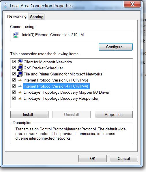
Used for configuration and monitoring of the system
Hosted webpage for configuration at IP address 192.168.123.10
USB: Standard USB Host Mode A Connector
Utilized for data logging by installing a USB thumb drive
www.luminator.com Page 7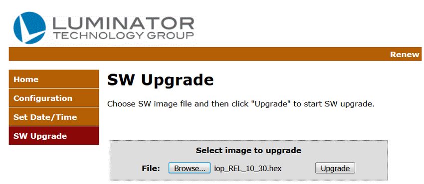
3.5 CONFIGURATION SETTINGS
DMX Channel – The DMX protocol allows for multiple channels for communicating to different items or
functions that reside on the DMX communication bus. The values for the current Atomizer are shown in the
following table.
TABLE 1: DMX CHANNEL CONTROL FUNCTIONS
Channel Function Value Percent/Setting
000 010 No function
1 Fan Speed
011 255 1–100%
000 010 No function
2 Haze Output
011 255 1–100%
000 151 No function
3 Remote Clean Function 152 159 Remote clean function
160 255 Standby mode
Fan Speed: The fan speed setting.
The higher the setting, the faster the atomized solution is dispersed in the space. This value is typically fixed
for a specific environment.
Max Atomizer Power: The maximum Atomizer output setting.
This setting directly correlates to how much Grignard Pure is being dispensed at any given time.
NOTE: HIGHER SETTINGS ARE NOT NECESSARILY BETTER, AS THEY WOULD CAUSE THE CONCENTRATION
TO “OVERSHOOT” THE DESIRED LEVEL.
Atomizer On Time (seconds): Indicates the amount of time the Atomizer is ON (dispensing Grignard Pure).
This allows for fine adjustments to the amount of Grignard Pure that is dispensed.
NOTE: THE CONTROLLER CONSTANTLY ADJUSTS OFF TIME BASED ON THE SENSOR READINGS. IF THE
LEVEL IS TOO HIGH THEN THE OFF TIME IS GRADUALLY INCREASED. IF THE LEVEL IS TOO LOW THE OFF
TIME IS GRADUALLY DECREASED.
Hysteresis: Adjusts the maximum level before a change is made to change the Atomizer output.
This is often referred to as “dead band”. Example: If the desired set point is 4000 and the hysteresis is 1000,
the Controller will allow the concentration level to fluctuate between 4000 and 5000 before taking any action.
PM Threshold (#/cm^3): The set point (or the desired concentration) of Grignard Pure.
This value represents the total number of detected vapor droplets between .3 micron and 2.5 microns in size
per cubic centimeter. At publication of this document, current efficacy testing concluded this level should be
approx 4000 detected particals/cm^3.
www.luminator.com Page 8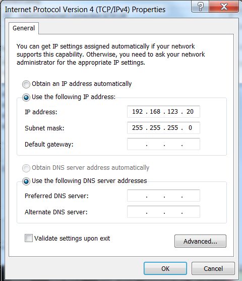
4        SYSTEM SENSOR
4.1 INTRODUCTION
       The Renew System Sensor features a PM2.5 Laser Difraction Sensor with RS485 Full Duplex Isolated Interface.
       The Sensor detects levels of Grignard Pure in the air and transmits this data to the Controller.

4.2 POWER
       The Sensor is powered from the Controller with 5V DC power source.

4.3 MOUNTING
       The Sensor should be mounted on a ceiling or wall that is free from direct air flow. E.g. Do not mount directly
       next to a HVAC air vent, HVAC return air vent, or ceiling fan.

       The Sensor grating should be positioned parallel to the floor or pointing downward to prevent accumulation of
       dust and debris in the Sensor housing.

4.4 CONNECTIONS
       The Sensor featueres a RS485 interface has the ability to include termination resistors via dip switch settings.
       Terminations resistors improve the signal integrity and help support longer cable runs which theoretically can
       reach up to 4000 feet.

Sensor Connector: 6 pin connector
              Used to communicate with the Sensor and supply power to the Sensor
              Full duplex RS485 plus power

www.luminator.com                                                                                            Page 9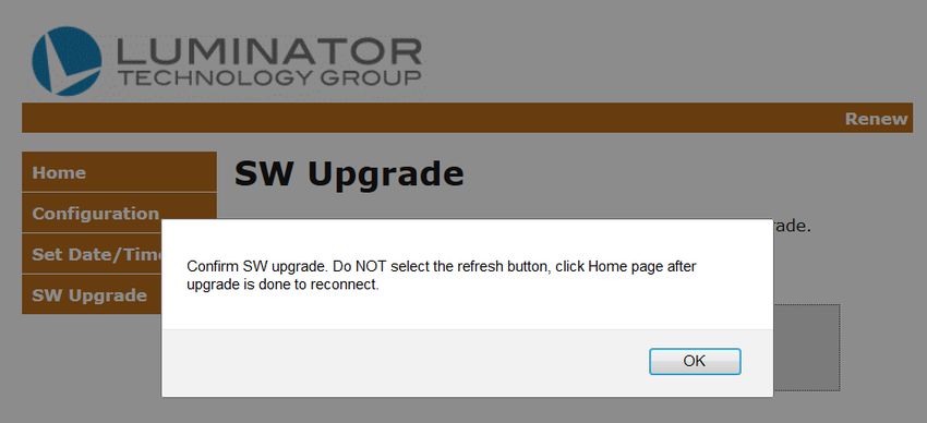
5         INITIAL SYSTEM SETUP
5.1 INSTALL THE ATOMIZER
    1. Mount the Atomizer and securely fasten according to the instructions in section 2.
    2. Attach the power cable to the Atomizer and connect to a 120VAC power source.
    3. Ensure the reservoir has adequate levels of Grignard Pure.

5.2 INSTALL THE CONTROLLER
    1. Securely mount the Controller according to the instructions in section 3.
       NOTE: THE CONTROLLER DOES NOT NEED TO BE LOCATED NEAR THE ATOMIZER OR THE SENSOR.
    2. Connect the 5 Pin DMX cable from the Controller to the Atomizer.
    3. Plug the Controller into an available 120VAC outlet.

5.3 INSTALL THE SENSOR
    1. Securely mount the Sensor according to the instructions in section 4. A ceiling or high on a wall is ideal. The
       Sensor grate should be located parallel to the ground, or pointing downward to avoid dust accumulation inside
       the Sensor.
       NOTE: THE SENSOR DOES NOT NEED TO BE LOCATED NEAR THE CONTROLLER.
       NOTE: FOR BEST RESULTS LOCATE THE SENSOR A FAR DISTANCE FROM THE ATOMIZER
    2. Route the Sensor cable and connect the Sensor to the Controller.

5.4 ACTIVATE THE ATOMIZER
    1. Ensure the tubing connecting the reservoir to the Atomizer is free of air bubbles.
       NOTE: REFER TO STEP 4 AFTER APPLYING POWER IF THE FLUID TUBE IS EMPTY OR AIR BUBBLES ARE
       PRESENT.

    2. If the Atomizer is equipped with an on/off switch, depress the switch to the ON position.
    3. If the Atomizer is NOT equipped with a switch, plug in the Atomizer to connect to power.
    4. Wait a few minutes for the Atomizer to warm up before proceeding to step Error! Reference source not found..
       NOTE: SOME VERSIONS OF THE ATOMIZER DO NOT FEATURE A SELF-PRIMING PUMP. IF THE ATOMIZER
       FEATURES A MANUAL PUSH BUTTON SWITCH, FOLLOW THESE INSTRUCTIONS FOR FIRST-TIME SETUP, OR
       IF THE RESERVOIR HAS RUN DRY.

    5. Press the Prime Button located behind the panel with LED indicators.
       NOTE: THIS STEP IS ONLY NECESSARY IF THE FLUID TUBE IS EMPTY OR LARGE AIR BUBBLES ARE
       PRESENT.

        NOTE: THIS ACTION CAN GENERATE A VERY THICK BURST OF ATOMIZED GRIGNARD PURE WHICH
        GREATLY EXCEEDS THE EFFICACY LEVEL NEEDED. THIS INITIAL BURST WOULD NEED TO DISSIPATE TO
        LOWER LEVELS BEFORE THE SYSTEM WILL TURN BACK ON.

        NOTE: THE FLUID IN THE TUBING IS DETECTED BY A SENSOR. IF AN AIR BUBBLE OR NO FLUID IS PRESENT,
        THE SYSTEM WILL NOT OPERATE.

www.luminator.com                                                                                         Page 10
5.5 ACTIVATE THE CONTROLLER
1. If the Controller has already been configured for the installed space, the system will automatically being
operation as follows:
a. The system automatically detects the Sensor
b. The system automatically cleans the Sensor Fan
c. The system automatically calibrates based upon the background particulate matter (PM) levels
NOTE: BACKGROUND PM LEVELS ARE TYPICALLY 1% OF THE TOTAL PM THRESHOLD.
NOTE: WITH EARLY SOFTWARE VERSIONS THIS CALIBRATION STEP COULD TAKE SEVERAL MINUTES E.G. 8
MINUTES.
NOTE: EFFECTIVE ATOMIZED LEVELS OF GRIGNARD PURE MAY BE TOO SMALL TO BE VISIBLE.
NOTE: THE STATUS OF THE SYSTEM CAN BE VIEWED BY CONNECTING A LAPTOP PER THE INSTRUCTIONS
IN SECTION 0.
www.luminator.com Page 116 RENEW SYSTEM APPLICATION
6.1 INTRODUCTION
The Controller features a web application to provide the following functions:
System status
System configuration
Date and time setting
Firmware upgrades
Accessing this site is not necessary for the system to operate. However, it can be used to change system
parameters. Once ideal values are determined for an environment, they are stored in non-volatile memory and
should not require on-going changes.
The system does not need to be connected to a network in order to configure parameter settings on the
Controller. As the Controller is a fixed end point in a network, it can not implement DHCP to assign an IP
address to a laptop that is connected to the Controller. Therefore, a static IP address must be assigned to the
laptop.
The default static IP address for the Controller is 192.168.123.10.
In order to connect a laptop directly to the Controller, it must also have an IP address that is fixed and on the
same subnet. It can be any address on the same subnet, for example: 192.168.123.20.
For more information about setting a static IP address on a laptop computer, refer to Appendix A.
www.luminator.com Page 126.2 ACCESSING THE APPLICATION
Required items:
A laptop computer that is NOT connected to a network and has a static IP adress configured as
192.168.123.20
Standard Ethernet patch cable
1. Connect the Ethernet cable to the laptop and the Controller.
2. Once the static IP address is configured on the computer, open a web browser (e.g. Firefox, Google Chrome, or
Internet Explorer) and enter the fixed IP address. 192.168.123.10 into the browser search bar.
3. The status page titled Figure 4 : Renew Controller Web Page will appear.
FIGURE 4 : RENEW CONTROLLER WEB PAGE
6.3 CONTROLLER STATUS
The system status displays the various system states such as:
Connection to the Sensor
Automatic Sensor cleaning
Automatic Sensor calibration
Currently dispensing Grignard Pure
www.luminator.com Page 13 Atomizer is inactive
Current PM (particulate matter) Sensor reading
6.4 CONTROLLER CONFIGURATION
The Controller configuration allows the user to set the various parameters that impact the control loop and are
dependent on the installed environment.
Each environment is different depending upon HVAC systems, Fresh Air Replenishment, etc.
Some suggested starting values are provided in the following table.
FIGURE 5: EXAMPLE CONTROL SETTINGS
Setting Default Value Small Office Rail Car Gymnasium Comments
Should not change,
DMX Channel 1 1 1 1
dependent on the Atomizer
Spaces with minimal air movement
Fan Speed 125 255 125 255
should use higher settings
This number controls how many ml/min are
Max Atomizer Power 90 12 30 125
being utilized when the Atomizer is on
This controls how long the Atomizer stays on,
On Time (Seconds) 90 10 75 120 the off time between on times is constantly
adapting to the Sensor readings
This is the band above the PM threshold where
Hysteresis 1000 1000 1000 1000
no action is taken by the Controller
This is based on live virus efficacy testing,
PM Threshold (#/cm^3) 3500 3500 3500 3500 higher numbers are not necessarily more
effective
FIGURE 6 : CONTROLLER CONFIGURATION
www.luminator.com Page 146.5 CONTROLLER SOFTWARE UPGRADE
The Controller application interface supports easy software upgrades.
Required items:
A .hex file supplied by Luminator
1. Using a browser, select the file as shown in the following figure.
FIGURE 7: CONTROLLER SOFTWARE UPGRADE
2. The application will ask you to confirm the upgrade, as shown in the following figure.
FIGURE 8: CONTROLLER SOFTWARE UPGRADE
3. Once the upgrade is complete, the Controller will reboot with the new software.
4. Reconnect to the application by either clicking on the home tab, or restarting the browser and
reentering in the IP address: 192.168.123.10.
www.luminator.com Page 156.6 CONTROLLER DATE AND TIME SETTINGS
The Controller application interface supports easy date and time setting adjustments. Time and data
information is recorded in the system log files.
If the system is connected to a network switch that supports Simple Network Timing Protocol (SNTP), then the
Date and Time will automatically adjust. If the system is NOT connected to a network switch, then the date and
time can be adjusted manually.
NOTE: EARLY VERSIONS OF THE CONTROLLER DO NOT FEATURE A BATTERY BACKUP REAL-TIME CLOCK
FOR MAINTAINING TIME AND DATE INFORMATION.
NOTE: THE LOG FILES WILL CONTINUALLY UPDATE WITH A SEQUENTIAL TIME, BUT IF POWER IS TURNED
OFF, THE NEXT TIME POWER IS APPLIED, THE DATE AND TIME WILL RESUME WHERE IT LEFT OFF.
1. Select “Set Date/Time” from the menu.
2. Enter the desired settings.
3. Select “Set” to save the settings.
FIGURE 9: RENEW CONTROLLER DATE AND TIME
www.luminator.com Page 16APPENDIX
CONFIGURE A STATIC IP ADDRESS
These instructions are provided to setup a connection between a laptop and the Controller. This procedure is not
required in order for the system to operate, it is only needed to change initial configurations settings on the Controller
or to monitor system status.
1. Navigate to the “Control Panel” of the computer and select “Network and Sharing Center”
FIGURE 10: ACCESSING THE NETWORK SHARING CENTER
www.luminator.com Page 172. Select “Change Adapter Settings”
FIGURE 11: ACCESSING NETWORK ADAPTER SETTINGS
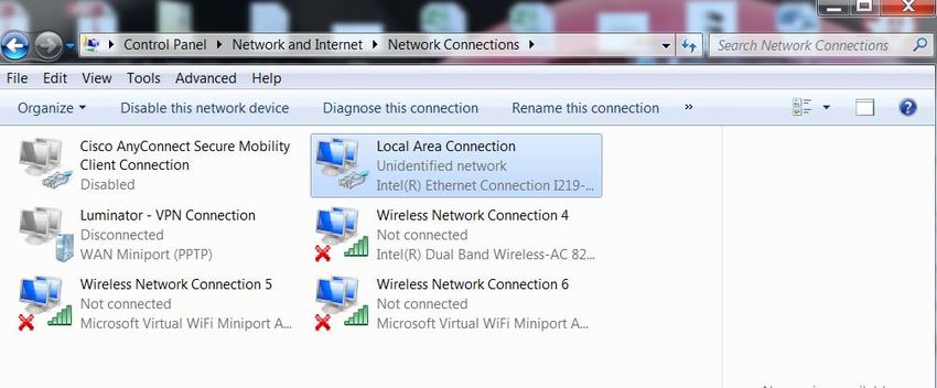
3. Select the “Local Area Connection”, right click and select “Properties”
FIGURE 12: MODIFY LAN CONNECTION SETTINGS
www.luminator.com Page 184. Select “Internet Protocol Version 4 (TCP/IPv4)” and click “Properties”
FIGURE 13: CHANGE LOCAL AREA NETWORK SETTINGS
5. Select “Use the Following Address” and set the static IP Address and Subnet mask on the same subnet
as the Controller. Example: 192.168.123.20 and 255.255.255.0
FIGURE 14: SETTING STATIC IP ADDRESS
www.luminator.com Page 19You can also read