MANAGEMENT OF ENERGY CONSUMPTION USING PROGRAMMABLE LOGIC CONTROLLERS (PLC'S)
←
→
Page content transcription
If your browser does not render page correctly, please read the page content below
Vol. 03, No. 3 (2021) 267-272, doi: 10.24874/PES03.03.003

                                    Proceedings on Engineering
                                             Sciences
                                                      www.pesjournal.net

  MANAGEMENT OF ENERGY CONSUMPTION
USING PROGRAMMABLE LOGIC CONTROLLERS
               (PLC’S)

Amin Al Ka’bi1

                                                                           ABSTRACT
Keywords:
Energy Efficiency; Energy Consumption; The implementation of efficient energy systems is considered as one of the most
Programmable Logic Controllers;        important requirements in modern building. The purpose of these systems is to
PLC’s.                                 regulate energy consumption and meanwhile to reduce the negative impact on
                                              the surrounding environment through an efficient management of available
                                              energy resources, including renewable and nonrenewable resources. The
                                              integration of mains power supply with the solar power supply, besides other
                                              energy resources is a key element in designing the required energy management
                                              system.
                                              In this paper, the usage of Programmable Logic Controllers (PLC’s) is
                                              proposed to control the energy consumed by various loads in the building based
                                              on real-time measurements of certain factors affecting the total amount of
                                              consumed energy. Hence, this paper presents a real time prototype design and
                                              implementation of an automated control system of mains electricity power
                                              distributed to various loads, using Allen Bradley MicroLogix 1100
                                              Programmable Logic Controller (PLC). The PLC is programmed using ladder
                                              diagram for intelligent switching of both solar power supply and diesel
                                              generator power supply units. Also, it is programmed in order to prioritize the
                                              usage of the available solar energy as much as possible. The Rockwell Software
                                              Logix 500 is used for programming a PLC, running on a host computer
                                              terminal. For completeness, the control program results are compared with a
                                              hardware interfacing module.
                                                                               © 2021 Published by Faculty of Engineeringg

1. INTRODUCTION                                                     order to integrate the control of a complex process. The
                                                                    controller actions in different modes can be monitored
An automated control system is the technology to control            with the use of personal computer (PC). A typical PLC
and process a large amount of data in a very short time.            consists of a power supply, processor, input/output (I/O)
The programmable logic controller (PLC) is a light-                 modules and specialized modules (Burali, 2012; Peng et
weight, low-cost and self-contained electronic apparatus            al., 2004). Figure 1 shows a PLC based control system. It
for a wide range of industrial automation applications.             consists of supervisory/ programming computer,
This is widely used to control a simple, repetitive task            electronic field instruments and other electro-mechanical
and connected to multiple PLCs or to a host computer in             devices such as switches, sensors and contactors at the

1
    Corresponding author: Amin Al Ka’bi
    Email: a.kabi@ack.edu.kw                                                                                               267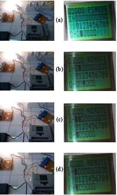
Amin Al Ka'bi, Proceedings on Engineering Sciences, Vol. 03, No. 3 (2001) 267-272, doi: 10.24874/PES03.03.003

input module and indicators, lamps, relays, control valves   logic operations of AND, OR, Exclusive OR, NAND,
etc., at the output modules. Nowadays, the buildings are     NOR, and latching (Bolton, 2006). Thus, the program
incorporated with more electrical appliances and             written by this method uses Boolean algebra needed to
electronic systems, which in turn require more controls.     design and analyse the program. Boolean logic and truth
PLC allows the user to combine its input / output (I/O)      table can be represented with Boolean equations and can
modules to form control system, as shown in Figure 2 of      be simplified to develop LD program (Jack, 2010). PLCs
the basic block diagram of PLC. In this system, control      provide many advantages over conventional relay type of
program for the specific application is stored in the        control, including increased reliability, more flexibility,
memory. This program is then executed as a part of the       lower cost, communication capability, faster response
cycle of internal operations of the PLC. The PLC is          time and convenience to troubleshoot (Rehg, 2002). They
continuously scanning memory to achieve control over         remove pulsing effect of switching operations, replace
the operation of the machine or process. Thus, the           mechanical relays, specially developed and relatively
controller repeatedly performs three steps: reads inputs     simple ladder diagram programming language makes the
from input modules, solves preprogramed control logic        electrician and technicians to develop and control
and generates outputs to output module based on the          program without any difficulty, use built in couplers for
control logic solutions. The automatic operation             driving input and output interface devices. It is possible
programmed in the PLC is triggered by an operator on         to design easily and modify the control program without
the supervisory computer (Ravikumar et al., 2013; Koo        any changes in the hardware connections to the input and
et el., 1998). At the same time information of the           output devices. This paper presents one of the building
programs can be recorded and monitored by the                automation applications of PLC in monitoring and
Supervisory Control and Data Acquisition (SCADA)             controlling of uninterrupted electricity to the load during
software.                                                    mains supply failure by considering the solar power
                                                             supply and diesel generator power supply as the alterative
                                                             standby energy sources, and is arranged as follows.
                                                             Section 2 describes the electricity supply switching
                                                             control system design for the controller. This includes
                                                             software development (algorithm, flow chart and LD
                                                             programming) of PLC. Section 3 discusses the hardware
                                                             module implementation, section 4 covers results and
                                                             discussions obtained by interface module and the final
                                                             section 5 contains conclusions.

                                                             2. DESIGN OF ELECTRICITY SWITCHING
                                                                CONTROL SYSTEM

         Figure 1. PLC Based Control System.                 The proposed design and implementation of intelligent
                                                             electricity supply switching control for building
                                                             automation involves both hardware and software
                                                             components. The hardware components include PLC as
                                                             a controller, input and output hardware interface
                                                             modules. Allen Bradley MicroLogix 1100, 1763-L1BBB
                                                             PLC is used as programmable controller which uses
                                                             Rockwell Software (RS) Logix 500 as control logic
                                                             software, running on the host computer terminal. The
                                                             development of software program and its implementation
                                                             using PLC is as follows: -

           Figure 2. Block Diagram of PLC.                   2.1 Software Development

The programming of PLC is performed by using a Ladder        The PLC embedded software system is different from
Diagram (LD) / ladder logic program (LLP). This is           conventional computer programming software. It deals
graphical programming language uses software to              with control signals for interaction of physical
emulate the hardwired devices of the relay ladder logic      environments rather than data computation. The
(Rullan, 1997; Samanta et al., 2005; Thiele et al., 2012;    development of the intelligent electricity supply
Rohner, 1996). The programmed operations work on a           switching control program is based on the logic
straightforward two-state ON or OFF basis and these          conditions given in the Truth Table I. In this table, Mains
alternate possibilities correspond to LOW OR HIGH            Power Supply input (MPS I/P) and Diesel Generator
(logical form) and 0 or 1 (binary form). The basic           Supply input (DGS I/P) are considered as two input
techniques involved in developing LD programs is to          variables to the PLC and the four output variables are
represent basic switching operations, involving digital      MPS, Solar Power Supply (SPS), DGS and DGS Starter

268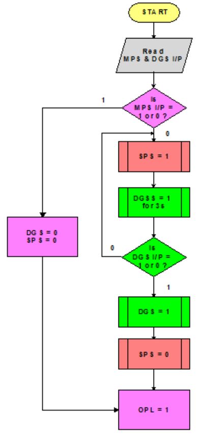
Amin Al Ka'bi, Proceedings on Engineering Sciences, Vol. 03, No. 3 (2001) 267-272, doi: 10.24874/PES03.03.003
(DGSS). The logic condition 0 is considered as OFF state indicated by 1. During the failure of MPS I/P, in order to
and the logic condition 1 is considered as ON state of the keep OPL uninterrupted, immediate switching ON of
variables. It is required to set the Output Power to the SPS is to be activated. At the same time DGSS switches
Load (OPL) to be in ON state by the output variables and to ON state for a delay of 3s to activate the DGS I/P.
is based on the automatic switching conditions of the When the DGS is activated, the control output switches
desired input variables. OFF the SPS and supply energy of the DGS to the OPL.
If the main power restored back, MPS I/P switch ON,
Table 1. Truth Table for Electricity Supply Switching then the OPL maintains ON. The DGS supply input can
Control be now switched OFF. The control flow diagram repeats
and maintains the uninterrupted electricity to the OPL
Input variables Output variables OPL during the mains failure.
MPS I/P DGS I/P MPS SPS DGS DGSS
(I/0) (I/1) (O/0) (O/1) (O/2) (O/3)
0 0 0 1 0 1 (3s) 1
0 1 0 0 1 0 1
1 1 1 0 0 0 1
1 0 1 0 0 0 1
2.1.1 Algorithm
The MPS I/P and DGS I/P are labeled as Input I/0 and
Input I/1 respectively. The four Outputs MPS, SPS, DGS
and DGSS are labeled as Output O/0, Output O/1, Output
O/2 and Output O/3 respectively. The algorithm steps
involved for switching the OPL in the ON state can be
summarized as follows.
STEP 1: I/0 = 0 and I/1 = 0
In this step, MPS I/P and DGS I/P both are OFF. To keep
the OPL in the ON state, SPS (O/1) becomes ON. At the
same instant, ON time of 3s is assigned for DGSS to
trigger the DGS switch to be start.
STEP 2: I/0 = 0 and I/1 = 1
MPS I/P OFF and DGS I/P is ON, as it is previously
stated in step 1 that DGS switches to ON due to the
trigger pulse from the DGSS start. Thus, as the DGS I/P
switch to ON state, DGS (O/2) supply energy to the OPL
and at the same instant SPS (O/1) switches to OFF state.
STEP 3: I/0 = 1 and I/1 = 1 Figure 3. Flow Chart of Control Program.
At this step, the MPS I/P switch to ON state. Due to this
DGS (O/2) switches to OFF state and the output variable 2.1.3 Programming
MPS (O/0) switch ON to supply energy to the OPL.
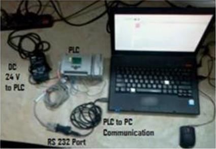
The programming is done by connecting the PLC and PC
STEP 4: I/0 = 1 and I/1 = 0 as shown in Figure 4. PLC is powered with the DC
The last step of the table shows that, as the MPS I/P in voltage of 24V and is communicated with PC through the
the ON state, and then the DGS I/P set to OFF state. MPS port RS-232. The software tool Rockwell Software (RS)
(O/0) is still in the previous state to supply energy to the Linx Classic is used for configuration of serial port
OPL. (Allen-Bradley, MicroLogix, 2015; Allen-Bradley,
RSLinx, 2015). The RS Logix 500 LD software supports
The above steps are repeated to keep the OPL in programming on windows operating system. LD
constantly ON state by the output variables during mains program uses graphical symbols for logic conditions in
failure. each instruction. The program emulates the flow of
electric current through a series of input conditions and
2.1.2 Flow Chart enables output conditions. The instructions were
executed rung by rung (Wanga et al., 2010; Birbir &
The flow chart can be written before programming and is Nogay, 2008). Figure 5 shows the LD program tested in
shown in Figure 3. At the beginning, all the input and the PC for automatic electricity supply switching control
output variables are to be read by the control program. application. This has six rungs from 0000 to 0005.
The OFF states are indicated by 0 and ON states are
269Amin Al Ka'bi, Proceedings on Engineering Sciences, Vol. 03, No. 3 (2001) 267-272, doi: 10.24874/PES03.03.003
the bit address is evaluated as true/ON. Due to this the
output OTL of address bit O: 0/2 enabled to switch ON
the DGS and at the same time SPS unlatches due to
instruction OTU of the address bit O: 0/1.
Rung 0004: As previously explained in the rung 0003
that the DGS is being switched ON due to enable of the
input variable address I: 0/1 of the DGS I/P. During
enabling of MPS I/P by the address bit I: 0/0 using XIC
instruction, the output variable of the DGS address bit O:
0/2 unlatches and MPS address bit O: 0/0 latches to
provide mains power to output power supply. Now the
DGS I/P can be switched OFF by the XIO instruction of
Figure 4. PLC to PC Communication. the address bit I: 0/1.
These rungs are developed based on the logic conditions Rung 0005: The last rung shows end of the ladder logic
of the algorithm, truth table and flow chart. The input program.
variables used are the MPS I/P and DGS I/P. These are
assigned to examine if open (XIO) / examine if close
(XIC) instructions. The bit addresses used are I: 0/0 and
I: 0/1. Here ‘I’ stands for input, ‘:0’ stands for 0 th word
and the last digits ‘/0’ and ‘/1’ indicates the bit addresses
of the corresponding input variables. The output
variables MPS, SPS, DGS and DGS Starter are assigned
to the Output Latch (OTL) and Output Unlatch (OTU)
instruction bit addresses. These are retentive output
instructions and the bit addresses used for output
variables MPS, SPS, DGS and DGS Starter are O: 0/0,
O: 0/1, O: 0/2 and O: 0/3 respectively. The term ‘O’
indicates output, ‘0’ indicates the 0th word of the output
address and ‘/0 to /3’ are the bit addresses of the output
variables. The sequence of operation of each rung is
given in the next section.
2.1.3.1 Sequence of Operations of Rungs
Rung 0000: In this rung the input variables MPS I/P and
DGS I/P are set to OFF. Then the address bits O: 0/1 and
O: 0/3 assigned to the OTL instructions, which
correspond to the address of output variables SPS and
DGS Starter are energized. Thus, the bit is set (turned on
or enabled).
Rung 0001: Here input variables MPS I/P and DGS I/P
are in the previous rung states and the 3s ON time delay
is use d to switch ON the DG starter push button by the
ON time timer instruction addressed as T4:1. The preset
value of is set to 3s and accumulator value is set to 0 in
the timer. Figure 5. LD Program for Electricity Switching
Control.
Rung 0002: At the end of the ON time delay, that is when
the pre-set value is equal to the accumulator count value 3. HARDWARE IMPLEMENTATION
of 3s of the T4:1 timer, the output of this timer is given
to the OTU instruction of the address bit O:0/3 for The hardware modules used for automatic switching
unlatching or releasing the push button of the DG Starter. control of electricity supply for building automation
includes Allen Bradley MicroLogix 1100, 1763-L1BBB
Rung 0003: In this rung, the input variable MPS I/P PLC integrated with input and output modules. Input and
assigned with the XIO instructions and DGS I/P is output hardware interface switching control modules are
assigned with examine if closed XIC instruction. When connected to the PLC for testing the control circuit and
the DGS I/P is forced ON by using this instruction, then program is shown in Figure 6.
270Amin Al Ka'bi, Proceedings on Engineering Sciences, Vol. 03, No. 3 (2001) 267-272, doi: 10.24874/PES03.03.003
Figure 6. Hardware Interfacing to the PLC
3.2 Output Interface Module shown in Figure 7(c). If MPS input restored back as
shown in Figure 7 (d), then MPS signal connects to OPL
The output module is interfaced to the output terminals without any delay and DGS I/P switches to OFF as
O/0, O/1 and O/2 of the PLC through the control relay indicated in Figure 7 (e).
(CR) coils MISH224L. These are used for switching the
MPS, SPS and DGS respectively to the output power load
(OPL) during the mains power failure for providing
uninterrupted supply. The terminal O/3 is connected to
CR coil of MISH212L for switching the DG starter ON
during mains failure along with SPS. The SPS uses 12V
DC battery and is charged by the solar panels connected
in series.
The series connection adds voltage rating of panels and
amperage (current) remains the same. The voltage stored
in the battery is then converted to AC voltage of 230V by
the solar inverter. 100W filament bulb is used at OPL for
testing the control system. The components of the
interfaced hardware module are provided with light
emitting diodes (LEDs) to observe the real time status of
the PLC. Also, the same status indicates on the PLC’s
LCD display screen as well as on the LD program.
4. RESULTS AND DISCUSSION
The control system operates according to the design
proposed for automatic electricity supply switching
control. The observations are monitored for both inputs
and outputs to the PLC along with the real time status of
the hardware modules indicated by the LEDs are shown
in Figure 7.
It is clear from the Figure 7(a) that, during the failure of
MPS input signal at I/0, at the same time both outputs
SPS O/1 and DGS starter O/3 will switch ON as per
control program. The SPS connects to load OPL and Figure 7. Variations of input and output variables of
DGS starter switch ON the DGS. The starter switches ON electricity supply control. (a) Switching ON of SPS and
for a time delay of 3s and then switches OFF as shown in DGSS during mains failure, (b) Switching OFF of
Figure 7(b). Thus, the starter of DGS acts as a push to ON DGSS after delay of 3s by keeping SPS intact, (c)
button to turn ON the diesel generator. After switching Switching ON of DGS and switching OFF of SPS, (d)
ON of the DGS output O/2, SPS switches to OFF, as Switching OFF of DGS O/P during restore back of MPS
271Amin Al Ka'bi, Proceedings on Engineering Sciences, Vol. 03, No. 3 (2001) 267-272, doi: 10.24874/PES03.03.003
During the changeover period of the switch, bulb shows Controller (PLC). The PLC is programmed using ladder
no variations in the intensity of illumination. This diagram for intelligent switching of both solar power
indicates that the switching speed is very high due to the supply and diesel generator power supply units.
use of PLC as a controller to provide uninterrupted power The proposed ladder logic control program works
supply. That is the results observed on the LCD display satisfactorily in accordance with the design
screen of the controller based on our software design considerations. It was found from the results of real time
correlate well with real time prototype hardware interface prototype hardware interfacing module that during
modules. Thus, it may be inferred that proposed model switching control operations it provides uninterrupted
works satisfactorily. electricity supply in building. Thus, it may be inferred
that the proposed model be considered in building
5. CONCLUSIONS automation applications.
This paper presented a real time prototype design and Acknowledgment
implementation of an automated control system of mains This project was funded “FULLY” by Kuwait
electricity power distributed to various loads, using Allen Foundation for the Advancement of Sciences, under
Bradley MicroLogix 1100 Programmable Logic project code “PN18-15EE-01”.
References:
Allen-Bradley (2015). MicroLogix 1100 programmable controller, User Manual. Rockwell Automation, Bulletin 1763
controllers and 1762 Expansion I/O. 1763-UM001C-EN-P.
Allen-Bradley (2015). RSLinx® classic getting results guide. Rockwell Automation, LINX-GR001O-EN-E.
Birbir, Y., & Nogay, H. S. (2008). Design and implementation of PLC-based monitoring control system for three-phase
induction motors fed by PWM inverter. International journal of systems applications, engineering & development.
2(3), 128-135.
Bolton, W. (2006). Programmable logic controllers. Burlington, MA 01803, Elsevier Newnes.
Burali, Y. N. (2012). PLC based industrial crane automation & monitoring. International Journal of Engineering and
Science, 3(1), 1-4.
Jack, H. (2010). Automating manufacturing systems with PLCs. Textbook, ISBN: 987-0-557-34425-3.
Koo, K., Rho, G. S., Kwon, W. H., Park, J., & Chang, N. (1998). Architectural design of an RISC processor for
programmable logic controllers. Journal of Systems Architecture, 44(5), 31l - 325.
Peng, S. S., & Zhou, M. C. (2004). Ladder diagram and Petri- Net-based discrete-event control design methods. IEEE
transactions on Systems, Man, and Cybernetics - Part C (Applications and Reviews), 34(4), 523-531.
Ravikumar, & Singal, S. K. (2013). Computer based control of operation and maintenance of SHP plants. International
Journal of Engineering Research and Technology, 6(5), 651-658.
Rehg, J. (2002). PLC laboratories – the next generation. ASEE Annual Conference & Exposition. Montreal, June 16-19.
Rohner, P. (1996). PLC: Automation with programmable logic controllers; a textbook for engineers and technicians.
Kensington, N.S.W, UNSW Press.
Rullan (1997). A., Programmable logic controllers versus personal computers for process control. Computers & Industrial
Engineering, 33(1-2), 421-424.
Samanta, T., Sarkar, D., & Dasgupta, S. (2005). PC-PLC based vacuum control system for superconducting cyclotron at
vecc. 10th ICALEPCS, International Conference on Accelerator & Large Expt. Physics Control Systems. Geneva, Oct
10-14,1-4.
Thiele, G., Renner, L., & Neimeier, R. (2012). Programmable logic controllers. Control systems, Robotics and
Automation, ©Encyclopedia of Life Support Systems (EOLSS), Germany.
Wanga, R., Song, X., Zhu, J., & Gu, M. (2010). Formal modeling and synthesis of programmable logic controllers.
Journal of Computers in Industry, 62, 23-31.
Amin Al Ka’bi
Department of Electrical Engineering,
School of Engineering,
Australian College of Kuwait,
Kuwait
a.kabi@ack.edu.kw
272You can also read