TT TABLETOP ROBOT - IAI America
←
→
Page content transcription
If your browser does not render page correctly, please read the page content below
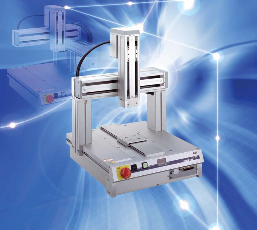
TT
                                         TA B L E T O P R O B O T

High accuracy        ±0.02mm

Types                Gate / Cantilever

Numbers of axes      2 axes / 3 axes

Work                 200 X 200
envelope             400 X 400

Number of
                     3000 points
positioning points

                                               www.intelligentactua tor.com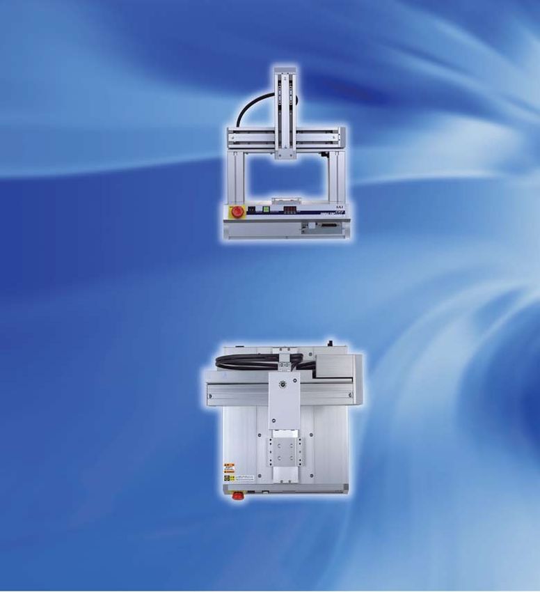
Tabletop Robot - Features

        A compact robot that is easy to use yet

        High-performance tabletop robot
        available at an amazingly low price

                                                                        Positioning repeatability of ±0.02 mm
                                                                        An encoder eliminates the possibility
                                                                        of mis-stepping
                                                                        Adoption of a rigid base, ball screw and servo control motor

                                                                        The TT employs a rigid base made of aluminum
                                                                        extruded material. It also uses a high-accuracy ball
                                                                        screw and a servo control motor to allow precision
                                                                        and eliminate mis-stepping.
                        Cross-sectional view of TT base

                  Built-in XSEL controller
                  High path accuracy and constant speed

                  The TT utilizes the high path accuracy and constant
                  speed of the XSEL controller. Additionally, it
                  provides the same extensive functions and
                  commands as the XSEL controller.
                  With the 3-axis specification, the TT lets you
                  perform three-dimensional arc interpolation and
                  path movement. You can also use the TT together
                  with a teaching pendant, PC software or other
                  tools.
                  A maximum of 64 programs can be stored, and up
                  to 16 programs can be run simultaneously. Up to
                                                                                Three-dimensional path movement
                  3,000 positions can be registered.

1   Tabletop Robot TT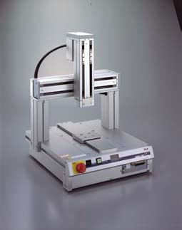
highly functional

            Gate type or cantilever type
            The gate type for high rigidity or the cantilever
            type for a savings in workspace

            The gate type has its Y-axis fixed, so it withstands
            unbalanced loads well and is suitable in
            applications where the Z-axis receives a heavy
            load, as well as applications where a large portion          Gate type                      Cantilever type
            of the load overhangs the slider.
            The cantilever type provides a wide, open work
            surface, so it is ideal when your equipment will be
            handling larger loads or loads with an irregular
            shape in a fixed condition.
                                                                   Select one of two operating ranges
                                                                   2020 Type (200 mm) or 4040 type (400 mm)
                                                     570mm
    370mm

                                                                   In addition to offering two model types (gate type
                                                                   and cantilever type), the TT also provides two
                                                                   selectable operating ranges. Choose 200 mm x 200
                                                                   mm (2020 type) or 400 mm x 400 mm (4040 type) as
                                                                   the operating range (X-axis/ Y-axis) of the actuator.
                                                                   Whether your equipment is handling small loads or
                                                                   large loads, you can select an appropriate model to
                                                                   operate in the appropriate range.
                                                                   The TT is available in a 2-axis specification and a
                                                                   3-axis specification. The 3-axis specification comes
               330mm                    530mm                      standard with a Z-axis brake, which prevents the
                                                                   slider from falling when the power is off.
             2020 Type                4040 Type

            Supporting field networks                                              Replacing programs
                                                                                   Sending work data
            (optional)                                                             (IAI protocol)

            Configured to support DeviceNet, CC-Link,                                                         HUB
            ProfiBus and Ethernet
                                                                                                                       PC
                                                                                                              HUB
            The TT can be connected to a common field
            network such as DeviceNet, CC-Link, ProfiBus and
            Ethernet for the transmission and acquisition of                                                  HUB
            position changes, production results and other
                                                                                                                       PLC
            data.                                                                  Send/receive I/O signals
                                                                                  (Modbus/TCP)

                                                                                                                    Tabletop Robot TT   2
Tabletop Robot - Examples of Application
Examples of Application
Coating Soldering
The TT's high-performance interpolation function makes it an ideal With its 3000-point positioning capability, the TT can easily
actuator for coating targets having a two- or three-dimensional apply solder to circuit boards, etc.
shape.
Applications Applications
Applying silicone to circuit boards, adhesive to Soldering electronic components.
speakers, sealant to fuel cells, etc.
Driving screws Circuit board inspection
The push-motion function of the Z-axis can be used to hold You can attach an image sensor to the Z-axis to inspect
a screwdriver against the load to tighten screws. circuit boards and components.
Applications Applications
Tightening screws into electronic components Checking circuit boards for mounting defects,
and automotive parts. inspecting processed parts.
3 Tabletop Robot TTTabletop Robot - Name of Each Part
Name of Each Part
X-axis slider opening
The X-axis slider opening has a step that prevents
the entry of foreign
matter.
Emergency stop switch
Z-axis A lock switch used to stop all actuator operations.
Digital program-selector switch
A digital switch used to select the program you
Y-axis want to run.
Function switch
A push button switch that can be used to
start/pause a program.
Panel window
A 4-digit, 7-segment LED that displays the program
number of the current program, error codes, etc.
Brake-release switch
A switch to forcibly release the Z-axis brake.
Network connector socket (optional)
A socket that accepts a field network connector.
( Refer to page 17.)
Teaching connector
A D-sub, 25-pin connector that accepts a teaching
-pendant cable or PC cable.
Z-axis brake
A brake that prevents the slider from falling when
the servo or power is
switched off.
X-axis Position-adjustment Knob
Used to fine-tune the slider position when the
servo is off (One knob is provided on each of
the X-, Y- and Z-axes.)
I/O connector
A 34-pin flat connector used for communicating with
external equipment. ( Refer to page 15.)
Power switch
Power connector
(A power plug is supplied with the actuator.)
Tabletop Robot TT 4Lineup
2-axis
Gate
Type
TT-A2 P7, P8
3-axis
TT Series
TT-A3 P9, P10
2-axis
Cantilever
Type
TT-C2 P11, P12
3-axis
TT-C3 P13, P14
Table of Specifications
Stroke (mm) Maximum Load capacity (kg) Positioning
Type speed repeatability Model Page
X-axis Y-axis Z-axis (mm/sec) X-axis Y-axis Z-axis (mm)
200 200 - TT-A2-I-2020 P7
2-axis 10 5 -
400 400 - TT-A2-I-4040 P8
50 TT-A3-I-2020-05B
Gate Type 200 200 P9
100 TT-A3-I-2020-10B
3-axis 10 - 2
50 TT-A3-I-4040-05B
400 400 P10
100 TT-A3-I-4040-10B
300 ±0.02
200 200 - TT-C2-I-2020 P11
2-axis - 4 -
400 400 - TT-C2-I-4040 P12
50 TT-C3-I-2020-05B
Cantilever 200 200 P13
Type 100 TT-C3-I-2020-10B
3-axis - - 2
50 TT-C3-I-4040-05B
400 400 P14
100 TT-C3-I-4040-10B
5 Tabletop Robot TTModel
TT - A3 - I - 2020 - 05B - DV
1 2 3 4 5 6
1 Series 2 Type 3 Encoder type 4 XY stroke (mm) 5 Z stroke (mm) 6 Option
A2 05B DV
A3: CC
A3 10B
2020 PR
TT I
4040 ET
C2 05B
C3: FT
C3 10B
P
1 Series 4 XY stroke
Name of the series X- and Y-axis stroke 2020 200mm
(The X-axis stroke is the same as the Y-axis stroke.)
4040 400mm
2 Type
Shape and number of component axes
5 Z stroke
A2 Gate, 2 axes A3 Gate, 3 axes Z-axis stroke 05B 50mm
C2 Cantilever, 2 axes C3 Cantilever, 3 axes * Since the Z-axis comes standard with a brake,
10B 100mm
"B" is added after the number indicating the stroke.
3 Encoder type 6 Option
Type of encoder installed in the actuator
Specify the options you want included in the actuator:
Only "Incremental" can be specified for the tabletop type. DeviceNet connection
DV specification PR ProfiBus connection
specification
I Incremental: Since the slider position data is erased
CC-Link connection
once the power is turned off, home CC specification ET Ethernet connection
specification
return will be required the next time the
power is turned on. FT Actuator bracket
specification P External I/O PNP
specification
System Configuration
Power supply: 100 to 230 VAC
* The actuator comes with a power
plug on the actuator side. The user
PLC
must provide the power cable.
I/O flat cable (supplied)
PC software (optional) Model: CB-DS-PIO020
Model: IA-101-X-MW Refer to P15
IA-101-TT-USB
IA-101-X-USBMW 2m
Refer to P18
Various field networks
(optional)
5m / 1m
• DeviceNet
PC cable
• CC-LINK
(Supplied with the PC software)
• ProfiBus
Model: CB-ST-E1MW050 (5m) 4m / 5m • Ethernet
CB-SEL-USB010 (1m)
Refer to P17
Teaching pendant (optional)
Model: IA-T-X/XD
SEL-T/TD
Refer to P18
Tabletop Robot TT 6TT Tabletop Robot
TT-A2-2020 Tabletop Robot/ Gate 2-axis specification
XY-axes: 200 mm
Type Gate, 2-axis Stroke X-axis: 200 mm / Y-axis: 200 mm Load capacity X-axis:10kg / Y-axis:5kg
Model specification items Series Type Encoder type XY-axis stroke Option
(Example) TT - A2 - I - 2020 - DV
Model / Specifications
Lead Stroke Speed Load capacity
Model Axis configuration Encoder type Motor type (kg)
(mm) (mm) (mm/sec)
(Note 1)
X-axis 6 200 1-300 10
TT-A2-I-2020- Incremental Pulse motor
Y-axis 6 200 1-300 5
* in the model number shown above indicates the applicable option(s).
Options Common Specifications
Name Model Drive system Ball screw (ø10mm, rolled C10)
DeviceNet connection specification DV Positioning repeatability ±0.02mm
CC-Link connection specification CC Backlash (Note 2) 0.1mm or less
ProfiBus connection specification PR Guide Direct-coupled endless cycling type
Ethernet connection specification ET Allowable load moment (Note 3) Ma : 6.5N • m Mb : 9.3N • m Mc : 16.4N • m
Actuator bracket specification FT Ambient temperature/humidity 5 to 40°C, 85%RH max. (non-condensing)
Actuator weight 14.8kg
Dimensions
* During home return the slider
moves to the ME, so be careful ME
to prevent contact with
18.2
surrounding parts.
SE
SE: Stroke end
2.5
ME: Mechanical end 70
60
Yst:200
40
80
50
42
30
80
72
70
50
HOME
ME
41.8
2.5
37.4
30
4-M5, depth 10
4-M4, depth 8
4-M5, depth 10 4-M4, depth 8 133.3 2-ø4H7, depth 5
2-ø4H7, depth 5 30 338.5 1.2
X-axis slider installation hole
369.7
Y-axis slider installation hole
338.5 ø5
88.2 ø8 hole
185 107
50
1
37.4
Position-adjustment
Position-adjustment knob
15 knob for Y-slider
T-groove (4 locations)
179
126
16.7 70 Xst:200 51.8 4.3 1.8
301
2.5 2.5
ME HOME SE ME
14
4.3
7.3
Detail view of T-groove
85
8
10 35 240 35 10
330
Applicable Controller Specifications
Applicable Maximum number Compatible Program Power-supply (Note 1) The load capacity is based on operation at an
Page
Controller of controlled axes encoder type operation voltage
acceleration of 0.3 G.
AC100V
Built-in 2 axes Incremental Program
AC200V
➝ P15 (Note 2) Applicable to each axis of X or Y.
Caution (Note 3) The load moment is a per-axis value based on a travel life
of 5,000 km. (Refer to page 19 for the load moment.)
7 TT-A2-2020TT Tabletop Robot
TT-A2-4040 Tabletop Robot/ Gate 2-axis specification
XY-axes: 400 mm
Type Gate, 2-axis Stroke X-axis: 400 mm / Y-axis: 400 mm Load capacity X-axis: 10kg / Y-axis: 5kg
Model specification items Series Type Encoder type XY-axis stroke Option
(Example) TT - A2 - I - 4040 - DV
Model / Specifications
Lead Stroke Speed Load capacity
Model Axis configuration Encoder type Motor type (kg)
(mm) (mm) (mm/sec)
(Note 1)
X-axis 6 400 1-300 10
TT-A2-I-4040- Incremental Pulse motor
Y-axis 6 400 1-300 5
* in the model number shown above indicates the applicable option(s).
Options Common Specifications
Name Model Drive system Ball screw (ø10mm, rolled C10)
DeviceNet connection specification DV Positioning repeatability ±0.02mm
CC-Link connection specification CC Backlash (Note 2) 0.1mm or less
ProfiBus connection specification PR Guide Direct-coupled endless cycling type
Ethernet connection specification ET Allowable load moment (Note 3) Ma : 6.5N • m Mb : 9.3N • m Mc : 16.4N • m
Actuator bracket specification FT Ambient temperature/humidity 5 to 40°C, 85%RH max. (non-condensing)
Actuator weight 33kg
Dimensions
* During home return the slider
moves to the ME, so be careful
to prevent contact with
18.2
2.5
surrounding parts. ME
SE: Stroke end
ME: Mechanical end SE
70
60
40
Yst:400
50
80
42
30
80
72
70
37.4
30
HOME
41.8 50
2.5
4-M5, depth 10 4-M4, depth 8 4-M5, depth 10 4-M4, depth 8
2-ø4H7, depth 5 ME
2-ø4H7, depth 5
Y-axis slider installation hole 333.3
X-axis slider installation hole
30 538.5 1.2
569.7
ø5
ø8 hole
Position-adjustment
1
knob for Y-slider
538.5
188.2
50 385 107 Position-adjustment knob
37.4
58
15 4.3 1.8
179
16.7 70 Xst:400 51.8
126
T-groove (4 locations)
301
2.5 2.5
ME HOME SE ME
14
4.3
7.3
85
Detail view of T-groove
8
10 35 440 35 10
530
Applicable Controller Specifications
Applicable Maximum number Compatible Program Power-supply
Page (Note 1) The load capacity is based on operation at an
Controller of controlled axes encoder type operation voltage acceleration of 0.3 G.
AC100V (Note 2) Applicable to each axis of X or Y.
Built-in 2 axes Incremental Program ➝ P15
AC200V
Caution (Note 3) The load moment is a per-axis value based on a travel life
of 5,000 km. (Refer to page 19 for the load moment.)
TT-A2-4040 8TT Tabletop Robot
TT-A3-2020 Tabletop Robot/ Gate 3-axis specification
XY-axes: 200 mm Z-axis: 50mm / 100mm
Type Gate, 3-axis Stroke X-axis: 200 mm / Y-axis: 200 mm / Z-axis: 50mm / 100mm Load capacity X-axis: 10kg / Z-axis: 2kg
Model specification items Series Type Encoder type XY-axis stroke Z-axis stroke Option
(Example) TT - A3 - I - 2020 - 05B - DV
Model / Specifications
Lead Stroke Speed Load capacity
Model Axis configuration Encoder type Motor type (kg)
(mm) (mm) (mm/sec)
(Note 1)
X-axis 6 200 1-300 10
TT-A3-I-2020- - Y-axis Incremental Pulse motor 6 200 1-300 -
Z-axis 6 50/100 1-300 (Note 2) 2
* and in the model number shown above indicate the Z-axis stroke and applicable option(s), respectively.
Options Common Specifications
Name Model Drive system Ball screw (ø10mm, rolled C10)
DeviceNet connection specification DV Positioning repeatability ±0.02mm
CC-Link connection specification CC Backlash (Note 3) 0.1mm or less
ProfiBus connection specification PR Guide Direct-coupled endless cycling type
Ethernet connection specification ET Allowable load moment (Note 4) Ma : 6.5N • m Mb : 9.3N • m Mc : 16.4N • m
Actuator bracket specification FT Ambient temperature/humidity 5 to 40°C, 85%RH max. (non-condensing)
Actuator weight 16.5kg
Dimensions
* During home return the slider
moves to the ME, so be careful
14.2
to prevent contact with ME
surrounding parts.
SE
SE: Stroke end
2.5
ME: Mechanical end 70
60
40
Yst:200
37.4
80
30
4-M5, depth 10
80
72
2-ø4H7, depth 5
70
58
50
42
30
HOME
ME
37.8
2.5
4-M4, depth 8
4-M5, depth 10
4-M4, depth 8
Position-adjustment 2-ø4H7, depth 5
83.3 knob for Z-slider
Z-axis slider installation hole
30 338.5 1.2
369.7
X-axis slider installation hole
76.8
338.5
135 107
51.8
ø5
Zst:50 (or 100)
ME
2.5
37.4 ø8 hole
50
197.8(247.8 if Zst = 100)
HOME
1
50
Position-adjustment
knob for Y-slider
407.3 (457.3 if Zst = 100)
ME
SE Position-adjustment knob
46
2.5
179
T-groove (4 locations)
102.5
16.7 70 Xst:200 51.8
4.3 1.8
14
2.5 2.5
ME HOME SE ME
85
4.3
7.3
Detail view of T-groove
10 35 240 35 10
8
(20) 330
(Cable projection length)
Applicable Controller Specifications
(Note 1) The load capacity is based on operation at an
Applicable Maximum number Compatible Program Power-supply
Controller of controlled axes encoder type
Page acceleration of 0.3 G.
operation voltage
(Note 2) If the stroke is 50, the maximum speed will be capped at
AC100V
Built-in 3 axes Incremental Program ➝ P15 280 mm/sec due to the shorter travel distance.
AC200V
Caution
(Note 3) Value for each of the X, Y and Z axes
(Note 4) The load moment is a per-axis value based on a travel life
of 5,000 km. (Refer to page 19 for the load moment.)
9 TT-A3-2020TT Tabletop Robot
TT-A3-4040 Tabletop Robot/ Gate 3-axis specification
XY-axes: 400 mm Z-axis: 50mm / 100mm
Type Gate, 3-axis Stroke X-axis: 400 mm / Y-axis: 400 mm / Z-axis: 50mm / 100mm Load capacity X-axis: 10kg / Z-axis: 2kg
Model specification items Series Type Encoder type XY-axis stroke Z-axis stroke Option
(Example) TT - A3 - I - 4040 - 05B - DV
Model / Specifications
Lead Stroke Speed Load capacity
Model Axis configuration Encoder type Motor type (kg)
(mm) (mm) (mm/sec)
(Note 1)
X-axis 6 400 1-300 10
TT-A3-I-4040- - Y-axis Incremental Pulse motor 6 400 1-300 -
Z-axis 6 50/100 1-300 (Note 2) 2
* and in the model number shown above indicate the Z-axis stroke and applicable option(s), respectively.
Options Common Specifications
Name Model Drive system Ball screw (ø10mm, rolled C10)
DeviceNet connection specification DV Positioning repeatability ±0.02mm
CC-Link connection specification CC Backlash (Note 3) 0.1mm or less
ProfiBus connection specification PR Guide Direct-coupled endless cycling type
Ethernet connection specification ET Allowable load moment (Note 4) Ma : 6.5N • m Mb : 9.3N • m Mc : 16.4N • m
Actuator bracket specification FT Ambient temperature/humidity 5 to 40°C, 85%RH max. (non-condensing)
Actuator weight 35kg
Dimensions
* During home return the slider
moves to the ME, so be careful
to prevent contact with
surrounding parts.
14.2
ME
SE: Stroke end
ME: Mechanical end
2.5
SE
70
60
40
Yst:400
37.4
80
30 4-M5, depth 10
70
80
72
2-ø4H7, depth 5
50
42
30
37.8 58
HOME
4-M4, depth 8
4-M5, depth 10 4-M4, depth 8
ME
2.5
2-ø4H7, depth 5
Z-axis slider installation hole Position-adjustment
283.3 knob for Z-slider X-axis slider installation hole
30 538.5 1.2
569.7
ø5 ø8 hole
76.8 538.5
58 335 107
1
Position-adjustment
50 51.8
ME knob for Y-slider
(or100)
Zst+147.8
Zst:50
HOME
2.5
37.4 Position-adjustment knob
50
SE
58
Zst+357.3
ME
2.5
46
4.3 1.8
179
16.7 70 Xst:400 51.8
102.5
T-groove (4 locations)
2.5 2.5
ME HOME SE ME
14
4.3
7.3
85
Detail view of T-groove
8
10 35 440 35 10
(20) 530
(Cable projection length)
Applicable Controller Specifications
(Note 1) The load capacity is based on operation at an
Applicable Maximum number Compatible Program Power-supply
Controller of controlled axes encoder type
Page acceleration of 0.3 G.
operation voltage
(Note 2) If the stroke is 50, the maximum speed will be capped at
AC100V
Built-in 3 axes Incremental Program ➝ P15 280 mm/sec due to the shorter travel distance.
AC200V
Caution
(Note 3) Value for each of the X, Y and Z axes
(Note 4) The load moment is a per-axis value based on a travel life
of 5,000 km. (Refer to page 19 for the load moment.)
TT-A3-4040 10TT Tabletop Robot
TT-C2-2020 Tabletop Robot/ Cantilever 2-axis specification
XY-axes: 200 mm
Type Cantilever 2-axis Stroke X-axis: 200 mm / Y-axis: 200 mm Load capacity Y-axis: 4kg
Model specification items Series Type Encoder type XY-axis stroke Option
(Example) TT - C2 - I - 2020 - DV
Model / Specifications
Lead Stroke Speed Load capacity
Model Axis configuration Encoder type Motor type (kg)
(mm) (mm) (mm/sec)
(Note 1)
X-axis 6 200 1-300 -
TT-C2-I-2020- Incremental Pulse motor
Y-axis 6 200 1-300 4
* in the model number shown above indicates the applicable option(s).
Options Common Specifications
Name Model Drive system Ball screw (ø10mm, rolled C10)
DeviceNet connection specification DV Positioning repeatability ±0.02mm
CC-Link connection specification CC Backlash (Note 2) 0.1mm or less
ProfiBus connection specification PR Guide Direct-coupled endless cycling type
Ethernet connection specification ET Allowable load moment (Note 3) Ma : 6.5N • m Mb : 9.3N • m Mc : 16.4N • m
Actuator bracket specification FT Ambient temperature/humidity 5 to 40°C, 85%RH max. (non-condensing)
Actuator weight 16.3kg
Dimensions
* During home return the slider
moves to the ME, so be careful
to prevent contact with 30 63.6 Xst:200
surrounding parts. 2.5 2.5
SE: Stroke end ME SE HOME ME
ME: Mechanical end
ME
26
SE
2.5
73 2-ø4H7, depth 5
8 42 23
14 30 29 120 4-M5, depth 10
Yst:200
29 44
50
40
20.5
40 4-M4, depth 8
HOME
60
58
30
ME ø5
2.5
ø8 hole
84
4-M4, depth 10
7.5
4-M5, depth 10
1
2-ø4H7, depth 5
Y-axis slider installation hole
Position-adjustment knob
Position-adjustment
42 73 49 knob for Y-slider
58
58
4.3 1.8
10
Position-adjustment
volume for X-slider
4.3
7.3
156
Detail view of T-groove
317
T-groove (4 locations)
50 41.8
6.2 60
49
1.5
85
8
310 10 30 148.8 45 135 45 1.2
10.6 320 28 405
Applicable Controller Specifications
Applicable Maximum number Compatible Program Power-supply
Controller of controlled axes encoder type
Page (Note 1) The load capacity is based on operation at an
operation voltage
acceleration of 0.2 G.
AC100V
Built-in 2 axes Incremental Program ➝ P15 (Note 2) Applicable to each axis of X or Y.
AC200V
Caution
(Note 3) The load moment is a per-axis value based on a travel life
of 5,000 km. (Refer to page 19 for the load moment.)
11 TT-C2-2020TT Tabletop Robot
TT-C2-4040 Tabletop Robot/ Cantilever 2-axis specification
XY-axes: 400 mm
Type Cantilever 2-axis Stroke X-axis: 400 mm / Y-axis: 400 mm Load capacity Y-axis: 4kg
Model specification items Series Type Encoder type XY-axis stroke Option
(Example) TT - C2 - I - 4040 - DV
Model / Specifications
Lead Stroke Speed Load capacity
Model Axis configuration Encoder type Motor type (kg)
(mm) (mm) (mm/sec)
(Note 1)
X-axis 6 400 1-300 -
TT-C2-I-4040- Incremental Pulse motor
Y-axis 6 400 1-300 4
* in the model number shown above indicates the applicable option(s).
Options Common Specifications
Name Model Drive system Ball screw (ø10mm, rolled C10)
DeviceNet connection specification DV Positioning repeatability ±0.02mm
CC-Link connection specification CC Backlash (Note 2) 0.1mm or less
ProfiBus connection specification PR Guide Direct-coupled endless cycling type
Ethernet connection specification ET Allowable load moment (Note 3) Ma : 6.5N • m Mb : 9.3N • m Mc : 16.4N • m
Actuator bracket specification FT Ambient temperature/humidity 5 to 40°C, 85%RH max. (non-condensing)
Actuator weight 35kg
Dimensions
* During home return the slider
moves to the ME, so be careful
to prevent contact with
30 63.6 Xst:400
surrounding parts.
2.5 2.5
SE: Stroke end ME SE HOME ME
2.5
ME
ME: Mechanical end
26
SE
2-ø4H7, depth 5
73
213.6 4-M4, depth 10
Yst:400
8 42 23
14 30 29
50
40
29 44
40 4-M4, depth 10
20.5
60
ø5 ø8 hole
58
HOME
30
1
ME
2.5
84
4-M5, depth 10
7.5
4-M4, depth 10
2-ø4H7, depth 5 Position-adjustment knob
Y-axis slider installation hole
4.3 1.8
142 73 49 Position-adjustment
knob for Y-slider
4.3
7.3
10 58
Position-adjustment
volume for X-slider Detail view of T-groove
Cam follower
156
317
22
50 41.8 Cam follower
T-groove (4 locations)
1.5
49
60
85
8
30 148.8 45 335 45
510 10
605
10.6 520 28
Applicable Controller Specifications
Applicable Maximum number Compatible Program Power-supply
Controller of controlled axes encoder type
Page (Note 1) The load capacity is based on operation at an
operation voltage
acceleration of 0.2 G.
AC100V
Built-in 2 axes Incremental Program ➝ P15 (Note 2) Applicable to each axis of X or Y.
AC200V
Caution
(Note 3) The load moment is a per-axis value based on a travel life
of 5,000 km. (Refer to page 19 for the load moment.)
TT-C2-4040 12TT Tabletop Robot
TT-C3-2020 Tabletop Robot/ Cantilever 3-axis specification
XY-axes: 200 mm Z-axis: 50mm / 100mm
Type Cantilever, 3-axis Stroke X-axis:200 mm / Y-axis:200 mm / Z-axis: 50mm / 100mm Load capacity Z-axis: 2kg
Model specification items Series Type Encoder type XY-axis stroke Z-axis stroke Option
(Example) TT - C3 - I - 2020 - 05B - DV
Model / Specifications
Lead Stroke Speed Load capacity
Model Axis configuration Encoder type Motor type (kg)
(mm) (mm) (mm/sec)
(Note 1)
X-axis 6 200 1-300 -
TT-C3-I-2020- - Y-axis Incremental Pulse motor 6 200 1-300 -
Z-axis 6 50/100 1-300 (Note 2) 2
* and in the model number shown above indicate the Z-axis stroke and applicable option(s), respectively.
Options Common Specifications
Name Model Drive system Ball screw (ø10mm, rolled C10)
DeviceNet connection specification DV Positioning repeatability ±0.02mm
CC-Link connection specification CC Backlash (Note 3) 0.1mm or less
ProfiBus connection specification PR Guide Direct-coupled endless cycling type
Ethernet connection specification ET Allowable load moment (Note 4) Ma : 6.5N • m Mb : 9.3N • m Mc : 16.4N • m
Actuator bracket specification FT Ambient temperature/humidity 5 to 40°C, 85%RH max. (non-condensing)
Actuator weight 18kg
Dimensions
* During home return the slider 13.6
moves to the ME, so be careful 30 Xst:200
to prevent contact with 2.5 2.5
surrounding parts. ME SE HOME ME
SE: Stroke end ME
26
ME: Mechanical end SE
2.5
37.4 4-M4, depth 8
4-M5, depth 10 30
60
40
2-ø4H7, depth 5
Yst:200
Position-adjustment
50
40
knob for Z-slider
30
42
50
120
HOME
4-M4, depth 8
ME 2-ø4H7, depth 5 4-M5, depth 10
2.5
84
Z-axis slider installation hole
ø5 ø8 hole
99.8 (149.8 if Zst = 100)
71
37.4
1
197.8 (247.8 if Zst = 100)
51.8
Zst:50 (or 100)
ME
2.5
HOME Position-adjustment knob
50
50
58
SE
2.5
Position-adjustment Position-adjustment 4.3 1.8
10
ME
knob for X-slider knob for Y-slider
46
4.3
7.3
156
124.5
317
T-groove (4 locations)
50
5 60 41.8 Detail view of T-groove
49
1.5
85
8
10.6 310 10 30 148.8 45 135 45 1.2
(34) 330.6 42 405
Applicable Controller Specifications
(Note 1) The load capacity is based on operation at an
Applicable Maximum number Compatible Program Power-supply
Page acceleration of 0.2 G.
Controller of controlled axes encoder type operation voltage
(Note 2) If the stroke is 50, the maximum speed will be capped at
AC100V
Built-in 3 axes Incremental Program
AC200V
➝ P15 280 mm/sec due to the shorter travel distance.
Caution (Note 3) Value for each of the X, Y and Z axes
(Note 4) The load moment is a per-axis value based on a travel life
of 5,000 km. (Refer to page 19 for the load moment.)
13 TT-C3-2020TT Tabletop Robot
TT-C3-4040 Tabletop Robot/ Cantilever 3-axis specification
XY-axes: 400 mm Z-axis: 50mm / 100mm
Type Cantilever, 3-axis Stroke X-axis:400 mm / Y-axis:400 mm / Z-axis: 50mm / 100mm Load capacity Z-axis: 2kg
Model specification items Series Type Encoder type XY-axis stroke Z-axis stroke Option
(Example) TT - C3 - I - 4040 - 05B - DV
Model / Specifications
Lead Stroke Speed Load capacity
Model Axis configuration Encoder type Motor type (kg)
(mm) (mm) (mm/sec)
(Note 1)
X-axis 6 400 1-300 -
TT-C3-I-4040- - Y-axis Incremental Pulse motor 6 400 1-300 -
Z-axis 6 50/100 1-300 (Note 2) 2
* and in the model number shown above indicate the Z-axis stroke and applicable option(s), respectively.
Options Common Specifications
Name Model Drive system Ball screw (ø10mm, rolled C10)
DeviceNet connection specification DV Positioning repeatability ±0.02mm
CC-Link connection specification CC Backlash (Note 3) 0.1mm or less
ProfiBus connection specification PR Guide Direct-coupled endless cycling type
Ethernet connection specification ET Allowable load moment (Note 4) Ma : 6.5N • m Mb : 9.3N • m Mc : 16.4N • m
Actuator bracket specification FT Ambient temperature/humidity 5 to 40°C, 85%RH max. (non-condensing)
Actuator weight 37kg
Dimensions
* During home return the slider
moves to the ME, so be careful 13.6
30 Xst:400
to prevent contact with
2.5 2.5
surrounding parts.
ME ME SE HOME ME
SE: Stroke end
26
ME: Mechanical end
SE
2.5
37.4
4-M5, depth 10 30
60 4-M4, depth 8
40
Yst:400
2-ø4H7, depth 5
50
40
30
42
50
Position-adjustment
4-M5, depth 10
213.6 knob for Z-slider
2-ø4H7, depth 5
ø5 ø8 hole
4-M4, depth 8
HOME
1
Z-axis slider installation hole ME
2.5
84
Position-adjustment knob
171
37.4 4.3 1.8
50 51.8
ME
Zst+49.8
2.5
(or100)
Zst:5
Zst+147.8
HOME
50
4.3
7.3
SE
2.5
Detail view of T-groove
10 58
Position-adjustment
knob for X-slider Position-adjustment
ME
46
knob for Y-slider
Cam follower
156
124.5
317
22
50 Cam follower T-groove (4 locations)
41.8
49
5 60
1.5
885
10.6 510 10 30 148.8 45 335 45 1.2
(44) 530.6 42 605
(Cable projection length)
Applicable Controller Specifications
(Note 1) The load capacity is based on operation at an
Applicable Maximum number Compatible Program Power-supply
Page acceleration of 0.2 G.
Controller of controlled axes encoder type operation voltage
(Note 2) If the stroke is 50, the maximum speed will be capped at
AC100V
Built-in 3 axes Incremental Program
AC200V
➝ P15 280 mm/sec due to the shorter travel distance.
Caution (Note 3) Value for each of the X, Y and Z axes
(Note 4) The load moment is a per-axis value based on a travel life
of 5,000 km. (Refer to page 19 for the load moment.)
TT-C3-4040 14Controller Specifications & I/O Assignments
Controller Specifications
Gate type Cantilever type
Item
2-axis specification 3-axis specification 2-axis specification 3-axis specification
Motor type Pulse motor (servo control)
Position detection method Incremental encoder
Power-supply voltage 100 to 115 VAC, 200 to 230 VAC, single-phase,±10%
Power-supply frequency 50Hz / 60Hz
Power-supply capacity Rated power output: 151.2 W --- Maximum instantaneous output (2 times)
Speed setting 1 to 300 mm/sec
Acceleration setting 0.01 to 0.3 G
Programming language Super SEL language
Number of programs 64 programs (16 programs)
(programs that can be run simultaneously)
Number of program steps 6000 steps (total)
Number of positions 3000 positions (total)
Program start Dedicated digital switch + Dedicated start switch
Data-storage device FLASH ROM
Data-input device Teaching pendant (model: IA-T-X)
PC software (model: IA-101-X-MW)
Numbers of I/O (input/output) points 16 input points / 16 output points (insulated DIO)
I/O connector 34-pin, flat
Supported field buses DeviceNet / CC-Link / ProfiBus / Ethernet
Protection functions Motor overcurrent, overload, motor-driver temperature check, overload check, encoder open detection, etc.
(Error codes are shown on the 7-segment LED on the front of the actuator.)
Specified ambient temperature/humidity 0 to 40°C, 20 to 90% (non-condensing)
Accessories Power connector, I/O flat cable
I/O Signal Table
Pin No. Classification Port No.
1 24V - Connected to 24V I/O power supply
I/O flat cable (accessory), model: CB-DS-PIO020
2 016 General-purpose input
General-purpose input 2m
3 017
4 018 General-purpose input
5 019 General-purpose input 2 1
6 020 General-purpose input
7 021 General-purpose input
8 022 General-purpose input No connector
9 023 General-purpose input
Input
10 024 General-purpose input
11 025 General-purpose input 34 33
12 026 General-purpose input
13 027 General-purpose input Flat cable (34-core)
14 028 General-purpose input
15 029 General-purpose input No. Color Wire No. Color Wire
16 030 General-purpose input 1 Brown 1 18 Gray 2
2 Red 1 19 White 2
17 031 General-purpose input
3 Orange 1 20 Black 2
18 316 General-purpose output 4 Yellow 1 21 Brown-3
19 317 General-purpose output 5 Green 1 22 Red 3
20 318 General-purpose output 6 Blue 1 23 Orange 3
General-purpose output 7 Purple 1 24 Yellow 3
21 319
8 Gray 1 25 Green 3
22 320 General-purpose output
9 White 1 Flat cable 26 Blue 3 Flat cable
23 321 General-purpose output 10 Black 1 27 Purple 3
24 322 General-purpose output 11 Brown-2 28 Gray 3
25 323 General-purpose output 12 Red 2 29 White 3
Output 13 Orange 2 30 Black 3
26 324 General-purpose output
14 Yellow 2 31 Brown-4
27 325 General-purpose output
15 Green 2 32 Red 4
28 326 General-purpose output 16 Blue 2 33 Orange 4
29 327 General-purpose output 17 Purple 2 34 Yellow 4
30 328 General-purpose output
31 329 General-purpose output
32 330 General-purpose output
33 331 General-purpose output
34 0V - Connected to 0V I/O power supply
15 Tabletop Robot TTI/O Wiring Diagram
Input Part: External input specification (NPN specification) Output Part: External output specification (NPN specification)
Item Specification Item Specification
Input power supply 24 VDC +10%-15% Load voltage 24 VDC
Input current 7 mA/circuit Maximum 100 mA/point
TD62084 (or equivalent)
ON/OFF voltages ON voltage---16.0 VDC min., OFF voltage---5.0 VDC max. load current 400 mA, peak (full current)
Insulation method Photocoupler insulation Leak current 0.1 mA/point max.
Equipment [1] No-voltage contact (with a minimum load of approx. 5 VDC/1 mA) Insulation method Photocoupler insulation
connected externally [2] Photoelectric proximity sensor (NPN type) Equipment [1] Miniature relay, [2] Sequencer input unit
[3] Sequencer transistor output (open-collector type) connected externally
[4] Sequencer contact output (with a minimum load of approx. 5 VDC/1 mA) P24*
[Output circuit]
[Input circuit]
Internal circuit
Dk Surge absorber
P24* 10Ω Load
Output
Internal circuit
terminal + External
_ power
External +
supply:
power _ 560Ω 24 VDC
supply: ±10%
24 VDC±10%
N*
3.3kΩ
Input terminal
*
P24 I//O interface pin No. 1
*
P24 I//O interface pin No. 1 N I//O interface pin No. 34
Input Part: External input specification (PNP specification) Output Part: External output specification (PNP specification)
Item Specification Item Specification
Input power supply 24 VDC ±10% Load voltage 24 VDC
Input current 7 mA/circuit Maximum 100 mA/point
TD62784 (or equivalent)
ON/OFF voltages ON voltage---8 VDC max., OFF voltage---19 VDC min. load current 400 mA/8 ports (see note)
Insulation method Photocoupler insulation Leak current 0.1 mA/point max.
Equipment [1] No-voltage contact (with a minimum load of approx. 5 VDC/1 mA) Insulation method Photocoupler insulation
connected externally [2] Photoelectric proximity sensor (PNP type) Equipment [1] Miniature relay, [2] Sequencer input unit
[3] Sequencer transistor output (open-collector type) connected externally
[4] Sequencer contact output (with a minimum load of approx. 5 VDC/1 mA) Note) 400 mA is the maximum total load current for eight ports from output port No.
300. (Maximum total load current for output port No. 300+n through No. 300+n+7 =
400 mA; where n = 0 or multiple of 8)
[Input circuit] [Output circuit] P24*
Input terminal
Internal circuit
Surge absorber
Internal circuit
10Ω
External Output
+
power _ 560Ω terminal External
+
supply: _
power
24 VDC±10%
Load supply:
3.3kΩ
24 VDC
±10%
N*
*
N I//O interface pin No. 34 *
P24 I//O interface pin No. 1
N I//O interface pin No. 34
Tabletop Robot TT 16Options
DeviceNet Connection Specification CC-Link Connection Specification
Model Model
(Actuator model)-DV (Actuator model)-CC
Item Specification Item Specification
Numbers of input/output points Maximum 256 input points / Maximum 256 output points Numbers of input/output points Maximum 256 input points / Maximum 256 output points
Communication standard An interface module certified under DeviceNet 2.0 is used. Communication standard CC-Link, Ver. 1.10 (certified)
Communication speed 500 / 250 / 125 Kbps Communication speed 10M / 5M / 2.5M / 625K / 156Kbps
Number of occupied node 1 node Station type Remote device station
Connector type (controller end) MSTBA2.5/5-G-5.08-AUM by Phoenix Contact (*1) Number of occupied stations 1 to 3 stations (selectable)
*1 Cable-end connector: SMSTB2.5/5-ST-5.08AU by Phoenix Contact (standard accessory) Connector type (controller end) MSTBA2.5/5-G-5.08-AUM by Phoenix Contact (*1)
*1 Cable-end connector: SMSTB2.5/5-ST-5.08AU by Phoenix Contact (standard accessory)
ProfiBus Connection Specification Ethernet Connection Specification
Model Model
(Actuator model)-PR (Actuator model)-ET
Item Specification Item Specification
Numbers of input/output points Maximum 256 input points / Maximum 256 output points Network specification 10BASE-T / 100BASE-T (auto negotiation)
Communication standard An interface module certified under ProfiBus-DP1.10 is used. Communication standard IEEE 802.3
Communication speed 12M/1.5M/500K/93.75/187.5K/93.75K/19.2K/9.6K Communication speed 10M/100Mbps
Address of occupied node 1 address (1 to 99; settable using the rotary switch on the board) Connector RJ-45
Connector type (controller end) D-sub, 9-pin connector Cable Category 5 UTP twisted cable
Actuator Bracket (A set of 4 pieces; supplied with bolts/nuts for installation to actuator)
Model Dimensions
TT-FT
20
8-ø7 hole
10 30 10
10
30 50
93
17 Tabletop Robot TTTeaching Pendant
Features
This is a teaching device that provides information on
functions such as programs, position input, running tests, IA−T−X/XD SE−T/TD
and monitoring. 120 45
28 66.6 110.0
Model
Model Description
218.3
IA−T−X Standard Type
265
IA−T−XD Deadman Switch Type
SEL−T Standard Type
SEL−TD ANSI Compatible Type (Deadman Switch)
90
Configuration 39.0 89.6
46.9
Model IA−T−X/XD SEL−T/TD
Compatible Controller Ambient Operating Temp./Humidity 0ºC~40ºC Below 85%RH
XSEL−P/Q Not subject to corrosive gases
Protective Structure or significant powder dust. IP54
IA−T−X/XD:4m
Weight Approx. 650g Approx. 400g (ex. Cable)
SEL−T/TD:5m
Cable Length 4m 5m
Display 20 Characters x 4 Lines (LCD)
PC Software (for Windows PCs only)
Features A startup support software program offering program/position input function, test operation
function, monitoring function, and more. The functions needed for debugging have been
enhanced to help reduce the startup time
Model IA−101−X−MW ( RS232C Cable Included)
Configuration
5m
RS232C Cable
PC Software (CD) CB−ST−E1MW050−EB
Model IA−101−TT−USB ( USB Cable Included)
Dummy Plug
Configuration DP−1
1m
USB Cable
PC Software (CD) CB−SEL−USB010
Dummy Plug DP−1
Model IA−101−X−USBMW ( USB Conversion adapter + Cable Included)
USB Conversion Adapter
Configuration IA−CV−USB
1m 5m
USB Cable RS232C Cable
PC Software (CD) CB−SEL−USB010 CB−ST−E1MW050−EB
Tabletop Robot TT 18Notes
Notes on Catalog Specifications
Speed "Speed" refers to the set speed at which the actuator slider is moved.
The slider accelerates from a stationary state. Once the set speed is reached, the slider will move at that
speed until immediately before the target position (specified position), where the slider will decelerate to a
stop.
Acceleration "Acceleration" refers to the rate of change of speed from a stationary state until the set speed is reached.
"Deceleration" refers to the rate of change of speed from the set speed until the slider stops.
/Deceleration
Acceleration and deceleration are set in "G" (0.3 G = 2940 mm/sec 2).
Duty IAI recommends that our actuators to be used at a duty of 50% or less as a guideline in view of the
relationship of service life and accuracy.
Duty (%) = Acceleration / Deceleration time X100
Motion time + Inactivity
Positioning "Positioning repeatability" refers to the positioning accuracy when the actuator is repeatedly moved
to a pre-stored position. It is different from "absolute positioning accuracy."
repeatability
Home The home is located on the motor side on the actuator for standard specification, or on the counter-motor side
of the actuator in the reversed-home specification.
During home return the slider moves until it contacts the mechanical end, and then it reverses its direction. Be
careful to prevent contact with surrounding parts.
Allowable load The load moment is calculated by assuming a travel life of 5,000 km. Note that if the specified
moment value is exceeded, the service life of the guide will be reduced. The direction of each
moment
moment and applicable reference point are shown below:
(Ma, Mb, Mc)
X-axis
X-axis:
Mb direction
Y-axis:
Ma direction
Z-axis:
Mc direction 36
Y-axis Z-axis
Y-axis: Reference position for
Mb direction Z-axis Ma moment
Z-axis: Z-axis:
Mb direction Ma direction
Y-axis:
Mc direction
86 Reference position for
Y-axis Ma moment
X-axis: X-axis:
Mc direction Ma direction
67.5
Reference position for
X-axis Ma moment
19 Tabletop Robot TTProgramming
Super SEL Language
Super SEL is one of the simplest of many robot languages available today.
Super SEL has single-handedly resolved the age-old challenge of "embodying advanced controls using simple
language."
Super SEL employs the step method in which all steps are executed one by one from the top. Since commands are
input in the order of operations, even a beginner can easily create a program.
Programming in Super SEL involves two types of data: the "program data" used for executing axis movement
commands, external communication commands and various other commands; and the "position data" consisting
of the record of positions to which each axis will be moved.
Up to 6000 steps of program data can be input, and these command steps can be divided into a maximum of 64
individual programs.
Up to 3000 positions can be registered, with each position consisting of data corresponding to three axes.
To move each axis, simply include a movement command in the program data and specify the number
corresponding to the desired position data. The axis will then move to the position registered under the specified
position data number.
Program data Position data
Tabletop Robot TT 20Sample Program 1 Soldering
Operation Overview
Register solder positions as position data and move the soldering head (attached to the Z-axis) using a
program to the registered positions sequentially.
Operation sequence
P11 P1 P11 P12 P2 P12 P13 P3 P13
P1 P8 P14 P4 P14 P15 P5 P15 P16 P6 P16
P17 P7 P17 P18 P8 P18 (Back to P11)
P2 P7
P11 P12 P17 P18
X-axis P13 P14 P15 P16
P3 P6
Z-axis
P4 P5 P1 P2 P7 P8
P3 P4 P5 P6
Y-axis Y-axis
Top view of circuit board Side view of circuit board
Position data
X-axis Y-axis Z-axis X-axis Y-axis Z-axis
P1 10 150 50 P11 10 150 0
P2 20 140 50 P12 20 140 0
P3 30 150 50 P13 30 150 0
P4 40 140 50 P14 40 140 0
P5 40 110 50 P15 40 110 0
P6 30 100 50 P16 30 100 0
P7 20 110 50 P17 20 110 0
P8 10 100 50 P18 10 100 0
Program
Step Extension condition Input condition Command Operand 1 Operand 2 Output condition Comment
1 HOME 100 Bring only the Z-axis to home
2 HOME 11 Bring the X- and Y-axes to home
3 VEL 100 Set the speed to 100 mm/sec.
4 ACC 0.3 Set the acceleration to 0.3 G
5 TAG 1 Destination of GOTO 1 in step 32
6 WTON 16 Stop until start button input 16 turns on
7 MOVP 11 Move to above position 1 (= position 11)
8 MOVP 1 Move (descend) to position 1
9 TIMW 3 Stop for 3 seconds
10 MOVP 11 Move (ascend) to position 11
11 MOVP 12 Move to above position 2 (= position 12)
12 MOVP 2 Move (descend) to position 2
13 TIMW 3 Stop for 3 seconds
14 MOVP 12 Move (ascend) to position 12
28 MOVP 18 Move to above position 8 (= position 18)
29 MOVP 8 Move (descend) to position 8
30 TIMW 3 Stop for 3 seconds
31 MOVP 18 Move (ascend) to above position 18
32 GOTO 1 Jump to TAG 1
33
34
21 Tabletop Robot TTSample Program 2 Coating
Operation Overview
Apply sealant to a plate along the path illustrated below.
The actuator moves continuously, without stopping, from position 1 to position 9 based on the movement path.
Operation sequence
P10 P1 P2 P3 P4 P5 P6 P7 P8 P9
* Move from P1 to P9 without stopping
P1 P8 P5
P4
P9
X-axis P7 P6
P10
P2 P3 Z-axis
P1
Y-axis Y-axis
Top view of plate Side view of plate
Position data
X-axis Y-axis Z-axis
P1 10 150 50
P2 40 150 50
P3 40 70 50
P4 10 70 50
P5 10 90 50
P6 20 90 50
P7 20 130 50
P8 10 130 50
P9 10 150 50
P10 10 150 0
Program
Step Extension condition Input condition Command Operand 1 Operand 2 Output condition Comment
1 HOME 100 Bring only the Z-axis to home
2 HOME 11 Bring the X- and Y-axes to home
3 VEL 100 Set the speed to 100 mm/sec.
4 ACC 0.3 Set the acceleration to 0.3 G
5 TAG 1 Destination of GOTO 1 in step 11
6 WTON 16 Stop until start button input 16 turns on
7 MOVP 10 Move to above position 1 (= position 10)
8 MOVP 1 Move (descend) to position 1
9 PATH 2 9 Move continuously from position 1 being the point of origin, to position 9
10 MOVP 10 Move to above position 1 (= position 10)
11 GOTO 1 Jump to TAG 1
Tabletop Robot TT 22Catalog Number CJ0082-1A-UST-3-0612 IAI America, Inc. IAI Industrieroboter GmbH Headquarters: 2690 W. 237th Street Torrance, CA 90505 (800) 736-1712 Ober der Roth 4, D-65824 Schwalbach am Taunus, Germany Chicago Office: 1261 Hamilton Parkway Itasca, IL 60143 (800) 944-0333 Atlanta Office: 1220 Kennestone Circle, Suite 108, Marietta, GA 30066 (888) 354-9470 www.intelligentactuator.com The information contained in this product brochure may change without prior notice due to product improvements.
You can also read