High-voltage DC distribution is key to increased system efficiency and renewable-energy opportunities

Page created by Dana Russell
 
CONTINUE READING
High-voltage DC distribution is key to increased system efficiency and renewable-energy opportunities
WHITE paper
White PAPER

High-voltage DC distribution is key to increased system
efficiency and renewable-energy opportunities
Written by: Stephen Oliver
Vice President, VI Chip Product Line
November 2012

                                       A transition to 400 VDC in power distribution and conversion will help meet
                                       greenhouse gas, efficiency, and renewable-energy goals.
                                       The pressure throughout the energy supply chain to deliver electrical power more efficiently is intense and
                                       growing. Most dramatically, the European Union’s response to the Copenhagen Accord puts forth a "20-20-20"
                                       Energy Strategy, with goals of a 20% reduction in energy consumption, a 20% reduction in greenhouse gases,
                                       and 20% reliance on power from renewable resources by 2020. These ambitious objectives are in place despite
                                       the enormous growth in major power consumers such as data centers ("server farms") as voice, data, and
                                       networks converge and merge, while user demands increase in the range of 5-10% annually.

                                       Existing solutions within the AC-DC conversion-system topology are struggling to provide even a few
                                       percentage points of large-scale improvement despite localized improvements in performance. The
                                       answer may be to look instead to a very different AC-DC structure, based on new approaches rather
                                       than merely incremental ones. Using high-voltage DC for power transmission, in conjunction with new
                                       conversion approaches, offers tangible and significant benefits for both sourcing options and system
                                       end-to-end performance. In fact, some work from France Telecom and China Mobile estimate that
                                       between 8% and 10% across the board can be saved by going to DC distribution.

                                       Ironically, this approach circles back to the 19th century and the earliest days of electric-power
                                       generation and distribution. Edison favored DC generation and distribution while Tesla advocated AC,
                                       with its availability of transformers for voltage step-up and step-down to reduce transmission (I2R)
                                       losses. (Transformers were the only practical way to achieve needed voltage conversion despite their
                                       efficiency of just 50-80%; cumbersome motor/generator combinations were a far-inferior alternative).
                                       The battle was big and the stakes were high, with technical, economic, and political consequences.

                                       As we all know, AC won that battle. But new technical developments in components and devices, along
                                       with additional power-system objectives, are acting as catalysts to make DC-based systems a better
                                       and available alternative. These developments include innovative conversion, control, and distribution
                                       approaches, much of which is enabled by advanced semiconductors and conversion topologies which
                                       function effectively in ways not previously possible. As a result, high-voltage DC (HVDC) systems are
                                       now practical for distribution and use within a building, office park, warehouse, school, and factory.

                                       Why use DC at all?
                                       Why consider high-voltage DC (380 V nominal/400 V peak) instead of traditional AC, which is well
                                       established and field proven for over 100 years? There are several aspects to the answer. DC does not
                                       require source synchronization as AC does, and can draw upon wind, solar, and the grid as each source
                                       is available. There are no phase balancing or harmonic issues, and no "stranded" equipment issues, all
                                       costly investments in infrastructure which may become obsolete or redundant.

                                       DC offers a lower total cost of ownership (TCO) in building wiring, copper, and connectors, along with
                                       an increase in efficiency of between 8 and 10%–truly significant. A properly configured DC system
                                       offers higher efficiency and more potential for power extraction from multiple available sources.

                                       There are also benefits which are not as immediately apparent. Most backup-energy sources, such as
                                       batteries and flywheels, are inherently DC. Further, telecom and server loads run on DC, so there are
                                       fewer intermediate, efficiency-robbing stages, along with greater reliability due to fewer potential points
                                       of failure with a DC-based approach.

                                                vicorpower.com              Applications Engineering: 800 927.9474                        Page 1
High-voltage DC distribution is key to increased system efficiency and renewable-energy opportunities
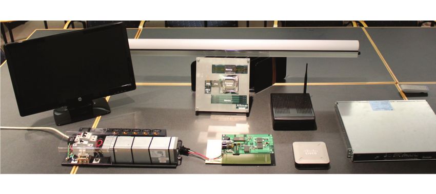
The HVDC approach is not just a speculative dream or laboratory curiosity. It has industry-wide support
                                    from critical component vendors, of course. It is also supported by industry consortia which are
                                    developing essential standards and interoperability specifications, such as the DCG+C [DC Components
                                    and Grid] consortium, the ITU [International Telecommunications Union] via standard L.1200, ETSI
                                    [European Telecommunications Standards Institute] via EN 300 132-3-1, the IEC [International
                                    Electrotechnical Commission], NTT/Japan [Nippon Telegraph and Telephone], and the IEEE.

                                    Topology makes a difference
                                    Before looking at the topology and implementation of a 400 VDC distribution approach, first look at the
                                    existing approaches used for major power consumers such as data centers or telecom central offices.
                                    In the data center, Figure 1, an incoming high-voltage AC line is stepped down, and then converted to
                                    DC so it can be paralleled with a battery-backup system. The DC is then converted back to high-voltage
                                    AC for distribution within the building, then converted yet again from AC down to lower-voltage DC,
                                    and then to voltages for the circuitry rails via DC-DC converters. Thus, there are four major conversion
                                    stages from incoming AC to final DC.

                      Figure 1.
      A typical data center has                      AC System
  four major conversion stages                                                    Conversion Steps: 4
        from incoming AC line                            1 UPS 2                    3         4
               to final DC rails.                                AC/              AC/        DC/
                                                        AC/
                                                                 DC               DC         DC     CPU
                                                        DC              AC 100
                                                                        ~ 200 V
                                                          Battery                       ICT eq.

                                    For the existing telecom system, there are just two major stages but with major points of inefficiency,
                                    Figure 2. The line AC is converted to 48 VDC and combined with the backup batteries; this 48 VDC line
                                    then supplies an array of DC-DC converters which provide the local, low-voltage rails needed
                                    for the circuitry.

                                    The HVDC system also has just two major conversion stages, but there is more to the end-to-end
                                    performance metric than the number of stages alone, as the efficiency of each stage is also critical. In
                                    the HVDC approach, the stages are both more efficient and more reliable.

                      Figure 2.
  For existing telecom systems,                    DC System (48 V)
          the two major stages                                                Conversion Steps: 2
    of current telecom systems                           1 RF                           2
are major points of inefficiency.                                                   DC/
                                                        AC/
                                                        DC                          DC             CPU
                                                                        DC 48 V

                                                              Battery                       ICT eq.

                                             vicorpower.com              Applications Engineering: 800 927.9474                         Page 2
The HVDC topology begins with the line AC rectified to 380 V-DC (nominal), with the battery backup
                                    also operating at that voltage, Figure 3. The DC voltage is then distributed throughout the facility and
                                    stepped down by local DC-DC converters to supply the rails of the processor and various loads. The
                                    system can draw on the outside AC line, batteries, and even onsite renewable sources such as wind and
                                    solar simultaneously or individually, in case there is a failure (such as grid problems due to a storm).

                      Figure 3.
      The line AC is rectified to
            380 VDC (nominal),                                                     HVDC System (380 V)
      while the battery backup          • High efficiency                                                                             • Low Copper
                                          (Few conversion                                                       Conversion Steps: 2     (Small current)
  also operates at that voltage                                                     RF
                                          steps)                              1                                      2                • Flexibility for
        in the HVDC topology.
                                        • High reliability                                                                              placing ICT
                                          (Batteries directly                 AC/                                  DC/                  equipment
                                                                                                                   DC        CPU
                                          supply power)                       DC               DC 380 V                                 (Long distance)

                                                                                    Battery                              ICT eq.

                                                            t                                                                         t

                                    Getting down to single volts
                                    The reality is that most circuitry operates from DC voltages below 12 V, and even down to the 1 V
                                    region. The challenge for any distribution/conversion system is to develop and deliver those low
                                    voltages (and their high currents) efficiently and reliably.

                                    HVDC can meet this requirement, as well, using several available building blocks. One is a Sine
                                    Amplitude Converter™ (SAC™), used in the form of a BCM®Bus Converter, which is an isolated, non-
                                    regulated DC-DC converter which uses a Zero-Voltage/Zero-Current Switching architecture, Figure 4.
                                    The SAC is like a traditional AC transformer except that it is DC input/output, and has an input/output
                                    voltage ratio which is fixed by design. For example, with a transformer ratio (K) of 1/8, it produces a
                                    50 VDC output from a 400 VDC input, and 47.5 V from a 380 V input.

                      Figure 4.
To support the HVDC topology,              +IN
                                                                         T2
            designers can use a                                          1    Q1
   Sine Amplitude Converter™                                              2

                     (SAC™) or
          BCM® Bus Converter                                                                  T1
                                                                         T2
    (an isolated, non-regulated                                           2
                                                                              Q2
             DC-DC converter).                                           1                    Q5

                                                                                                           T2
                                                                                                   1   2
                                                                         T2                                        +OUT
                                                                                                                 V

                                                                          2   Q3
                                                                         1               T1
                                                                                                                   –OUT
                                                                                                                 V

                                                                    T2                        Q6           T2
                                                                                                   2   1
                                                      Frequency
                                                     Lock/Control
                                                                         T2
                                                                         1    Q4
                                                                          2

                                           –IN

                                              vicorpower.com                   Applications Engineering: 800 927.9474                                     Page 3
The SAC reaches over 96% efficiency partially due to its fixed, high frequency (>1 MHz), soft-switching
                                     topology. The result is a power density of 70 W/cm3 ; a Vicor full-chip bus converter measuring just
                                     3.25×2.2×0.67 cm (1.28×0.87×2.265 in.)—comparable to a standard RJ-45 Ethernet plug, Figure 5—can
                                     deliver up to 330 W. The second block is the non-isolated buck-boost regulator, also using Zero-Voltage
                                     Switching and 1 MHz operation, Figure 6, resulting in small size and high efficiency of 97%.

                       Figure 5.
      This Vicor bus converter is
    the size of a standard RJ-45
       Ethernet plug, yet deliver
                    up to 330 W.

                       Figure 6.
Using Zero-Voltage Switching at
               1 MHz operation,          +IN                                                      +OUT
    the non-isolated buck-boost
       regulator offers small size
            and 97% efficiency.                                        IL

                                                                    ZVS B-B
                                                                     Control

                                        GND                                                        GND

                                     Working together, the SAC/BCM and buck-boost regulator provide an equalizer (adapter) function over
                                     the full span of input voltages for the normal service range as defined by ETSI, Figure 7. At the normal
                                     380 V point, the bus converter can drop the line down to 48 V, with the equalizer operating in a power-
                                     through mode (with a bypassed buck-boost). Thus, system efficiency is enhanced because the unit
                                     converts only when needed. If the DC voltage from the line or battery drops towards 260 V, the buck-
                                     boost converter "kicks in" and maintains the fixed 48 V rail.

                                     In either case, the architecture maintains high efficiency and allows for seamless, dynamic use of
                                     multiple sources—a rectified DC line, battery, and renewables—as they become available.

                                               vicorpower.com            Applications Engineering: 800 927.9474                       Page 4
Figure 7.
    Meeting the normal service        410 V                                                                               Abnormal Range
     range, as defined by ETSI,       400 V
                                                                                                                           (400 – 410 V)
                                                                                                                                                     If...
        requires understanding                                                                                                                                                   45-50 V                               98%
                                                                                                                                                     365 – 400 V                               Buck-Boost
          of corner-case design        380 V
                                                                                                                         380 V +/- tolerance                       BCM 1/8
                                                                                                                         Normal operating voltage                                              “Equalizer”          48 V +/–5%
             considerations and

                                                     Normal Service Range (260 V – 400 V)
                                                                                                                                                                     98%                                            (~45-50 V)
uses multiple functional blocks.                                                                                                                                                   Adapter
                                       350 V

                                                                                                                                                    If...
                                                                                                                                                    260 – 365 V                  32-50 V                               96%
                                                                                                                                                                                               Buck-Boost
                                                                                                                                                                    BCM 1/8
                                                                                                                                                                                               “Equalizer”          48 V +/–5%
                                      300 V                                                                                                                                                                         (~45-50 V)
                                                                                                                                                                    98%            Adapter              98%

                                       260 V

                                                                                            Abnormal Range (0 – 260 V)

                                         0V

                                    Legacy equipment is fully supported as well, starting with today's architecture of AC to 48 VDC
                                    rectification, followed by a 48 VDC power-distribution unit (PDU), and then DC-DC and DC-AC modules
                                    for the lower voltages as needed, Figure 8. In the transition phase, Figure 9, the rectification would be at
                                    line voltage producing 380 VDC, followed by a HV PDU, and then a mix of 380 VDC, 48 VDC, and lower-
                                    voltage AC (if needed) outputs, along with 48 V/12 V DC (or 9.6V) bus converters for the final rails.

                       Figure 8.
   The use of multiple modules
 ensures that legacy equipment
                   is supported            AC                                                                               48

                                                                                                                                                                                                              }
                                                                                                                                                                                           ICT equip.
                                          Switch                                                                           VDC                              PDU
                                                                                                                                                                                            (48 Vdc)
                                          board                                                                             RF
                                                                                                                                                                                           ICT equip.             Current
                                                                                                                                                                                            (48 Vdc)              Status
                                                                                                                                                                           D/A             ICT equip.
                                                                                                                                                                                           (AC input)

                       Figure 9.
     The transition phase uses a
        combination of rectifier,
                                           AC                                                                               380
step-up, and step-down stages.

                                                                                                                                                                                                              }
                                                                                                                                                                                           ICT equip.
                                          Switch                                                                            VDC                              PDU
                                                                                                                                                                                            (380 Vdc)
                                          board                                                                              RF
                                                                                                                                                                           D/D
                                                                                                                                                                                           ICT equip.             Transient
                                                                                                                                                                                            (48 Vdc)               Status
                                                                                                                                                                           D/A             ICT equip.
                                                                                                                                                                                           (AC input)

                                               vicorpower.com                                                                                        Applications Engineering: 800 927.9474                              Page 5
In this way, HV DC can be phased in without ripping "everything" out, which would be a costly and
                                       impractical requirement. After the transitional period, the intermediate voltage conversion after the
                                       PDU could be unnecessary: the 380 VDC would go directly to the loads to be converted down to the
                                       final needed voltages in a single step, Figure 10.

                        Figure 10.
As the technology and approach
        becomes established and
        accepted, the 380 V high            AC                      380

                                                                                                                                                                                                       }
                                                                                                                                                                             ICT equip.
 voltage DC would go directly to           Switch                   VDC                                               PDU
                                                                                                                                                                              (380 Vdc)
                                           board                     RF                                                                                                                                               100%
   the loads, and then converted
                                                                                                                                                                             ICT equip.
         to the lower-voltage rails                                                                                                                                           (380 Vdc)                              380 Vdc
                  in a single stage.                                                                                                                                                                                  Loads
                                                                                                                                                                             ICT equip.
                                                                                                                                                                             (380 input)

                                       A tangible demonstration
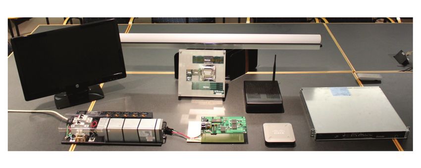
                                       Block diagrams and proposed architectures are good, but a working model is better, as shown by a
                                       complete 400 VDC system built using available, appropriate connectors, fuses, and distribution, Figures
                                       11 and 12. This collaboration between Emerson, Vicor, Anderson Electric, and Fujitsu powered multiple
                                       loads including an Intel VR12 processor, a LAN switch, a 1U server, a PC, and a monitor. As further
                                       testimony to the concept's validity, the 48 V was directly down-converted using a buck-boost plus bus-
                                       converter-like unit to 1 V without additional intermediate steps for the processor, yielding about 5%
                                       greater efficiency than the traditional approach.

                 Figure 11 & 12.
                                                                                                              ANDERSON
       This working model shows                                                                               Connectors
    a complete 400 VDC system
         built using commercially                                                                              A                               380 V - 400 V DC LED Lighting fixtures                               380 V Load
                                                                               FUJITSU 400 V DC power strip

 available connectors, fuses, and
              distribution cabling.                                                                                                                               ZVS 20-55 V     0.7-1.2 V Intel VR 12             Un-regulated
                                                                                                                                                                              SAC           CPU/memory
                                                                                                                                                                  B-B                                               48 V Load

                                                                                                                           HV IBC 1:8                                                                       VICOR
                                                                                                                                                                                        Un-regulated
                                                                                                                                                                     WLAN Switch
                                                                                                                                                                                        48 V Load

                                                                                                               A                               Equalizer                                Regulated
                                                                                                                                                                       1U Server
                                                                                                                                                ZVS-BB                                  48 V Load

                                             120 V,             AC/DC
                                                                                                                                                                                           Standard
                                                                                                                                 HV IBC 1:32                           Industrial PC       48 V Load
                                              15 A             Converter
                                            wall outlet                    380 V - 400 V
                                                                                                                    VICOR                                                                  Standard
                                                                                                                                                                     24” LED Monitor
                                                          EMERSON Network Power                                                                                                            48 V Load

                                                                                                                     VICOR Intel VR12.0
                                                                 LED monitor                                                                          LED lighting fixture                    1U Server
                                                                                                                      reference design

                                                              Emerson Network
                                                            Power Ac-DC Converter                                     VICOR Test Board                     WLAN Switch                      Industrial PC

                                                  vicorpower.com                                                     Applications Engineering: 800 927.9474                                                                   Page 6
The challenges and opportunities ahead
                    A combination of factors is making high voltage DC a very attractive solution to the energy
                    consumption dilemma. The merging of voice-centric telecom with data-centric networking (voice,
                    video, data) is driving increased power usage from information sources through end users. At the same
                    time, we face climate-change issues, limits on fossil fuels, and a need to integrate renewable sources.
                    Initiatives such as the Kyoto Protocol (1997), the Copenhagen Accord (2009) and the European Council
                    20-20-20 Energy Strategy provide a regulatory framework and set of ambitious goals for reducing
                    emissions of greenhouse gases, lowering energy consumption, and increasing use of renewable sources.

                    The electronics industry will be a big part of responding to these initiatives and meeting these goals. It
                    must be inventive, with radical, dramatic solutions rather than just incremental upgrades. It must be
                    proactive, at the leading edge of the transition, while using proven, safe, demonstrable technologies
                    which can shorten time to market. It must also collaborate on an industry-wide basis with alliances
                    among various vendors and organizations to set comprehensive standards, define commonalities, and
                    minimize barriers to adoption.

                    At the same time, the plan, process, and products must be commercially viable to encourage worldwide
                    involvement and adoption. Yes, these big challenges require big thinking and transformations, but this
                    industry has repeatedly shown it can act to meet and even lead them, as demonstrated by its many
                    radical transitions in process, products, and implementation over the years.

                    About the author
                    Stephen Oliver is Vice President of VI Chip® Product Line for Vicor Corporation. Steve has been in
                    the electronics industry for eighteen years, with experience as an applications engineer, product
                    development, manufacturing and strategic product marketing in the AC-DC, telecom, defense,
                    processor power and automotive markets. Previously with International Rectifier, Philips Electronics
                    and Motorola, Steve holds a BSEE degree from Manchester University, U.K. and an MBA in Global
                    Strategy and Marketing from UCLA and holds several power-electronics patents.

                                                         The Power Behind Performance

Rev 1.1   09/13		            vicorpower.com              Applications Engineering: 800 927.9474                         Page 7
You can also read