Evaluating the Field Performance of Windows and Curtain Walls of Large Buildings
←
→
Page content transcription
If your browser does not render page correctly, please read the page content below
Evaluating the Field Performance
                  of Windows and Curtain Walls of Large Buildings
                                    Mario D. Gonçalves, Patenaude-Trempe 1
                                            Robert Jutras, Air-Ins 2

                                                     Abstract

The most common and costly problems associated with the in-service performance of the vertical building
envelope of large buildings are related primarily with excessive air leakage and water intrusion. In
particular, windows and curtain walls, as well as their interface with the adjacent wall construction, are
determining elements in the performance of the vertical building envelope. Improved standards and design
principles have contributed in significantly improving the performance of window and curtain wall
systems, whether it is with respect to resistance to water penetration, air leakage resistance, wind load
resistance or condensation resistance. The reality, however, is that many buildings of recent construction
are still experiencing problems with the in-service performance of installed window and curtain wall
systems. Typically, these problems are often the result of poor installation, fabrication and lack of adequate
quality control.

This paper shall focus on evaluating the field performance of windows and curtain walls of large buildings
1) during the early stages of construction to validate as-built design and 2) during later construction stages
as a quality control measure. Large scale field testing to assess building envelope performance in large
buildings will be demonstrated through several practical case study examples.

The primary objective of this paper will be to provide an increased level of knowledge to the building
community for an improved awareness of the benefits and limitations of the use of field testing in
evaluating the field performance of the vertical building envelope of large buildings.

Keywords: building envelope, windows, curtain walls, field testing, air leakage, water infiltration.

1
  Mario D. Gonçalves is a senior engineer and building envelope consultant. He is the President of Patenaude-Trempe
- a Montreal, Quebec City and Boston based building envelope consulting firm with projects across eastern Canada
and the north-eastern United States. He is the lead author of this paper and can be reached at
m.goncalves@patenaude-trempe.com.
2
 Robert Jutras is a senior engineer specialized in the laboratory evaluation of building envelope components. He is the
President of Air-Ins Inc. - a full service building envelope testing laboratory located in Montreal, Quebec.

______________________________________________________________________________________
2007 Symposium on Building Envelope Technology                                 Page 1/14
Boston, Massachusetts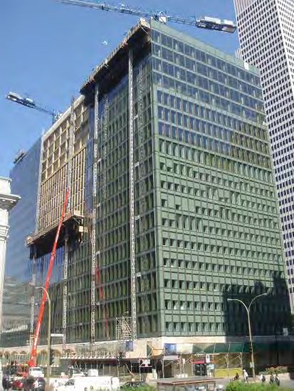
Evaluating the Field Performance
of Windows and Curtain Walls of Large Buildings
Mario D. Gonçalves, Patenaude-Trempe
Robert Jutras, Air-Ins
Michael Velji, VP Engineering
Introduction
Windows and metal & glass curtain walls generally represent as much as 50% to 100% of the exterior
cladding of large buildings and are determining elements in the performance of the vertical building
envelope. They are often an important architectural feature of a building and represent a significant portion
of the overall cost of a building construction or renovation project. As a determining element in the
performance of the vertical building envelope, they must be air and water tight, prevent condensation from
occurring on the interior surfaces and resist wind load and other exterior forces acting on the building
envelope. Given the ever growing complexity and variety of modern building envelopes, the evaluation of
their performance in the pre-construction and construction phase is essential in order to avoid undesirable
and costly problems during the service life of the building.
Figure 1: Metal & glass curtain wall - Figure 2: Metal & glass curtain wall -
new construction (New York, NY) building reclad (Montreal, QC)
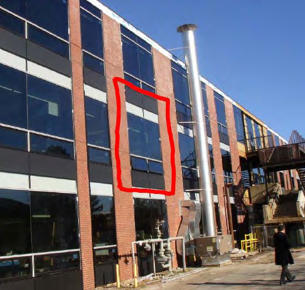
Figure 3: Aluminum punch windows Figure 4: Aluminum punch windows
and precast concrete (Montreal, QC) and brick cladding (New York, NY)
______________________________________________________________________________________
2007 Symposium on Building Envelope Technology Page 2/14
Boston, Massachusetts
Performance Requirements

Any form of water infiltration to the interior side of a building, excessive air leakage resulting in: 1)
discomfort to building occupants; 2) the formation of excessive condensation on the interior side of the
building or 3) the formation of icicles on the exterior side of the building, would be unacceptable to any
building owner or occupant. This being said, one of the primary performance criteria for any window or
curtain wall system is that they provide an appropriate level of resistance to water penetration and air
leakage resistance.

    Figure 5: Example of water infiltration within a        Figure 6: Example of water infiltration at a punch
    curtain wall assembly.                                  window assembly.

    Figure 7: Example of exterior icicle formation due     Figure 8: Example of excessive interior frost
    to excessive air exfiltration within a curtain wall    formation due to excessive air infiltration at a
    assembly.                                              window/wall interface.

Resistance to water penetration and air leakage resistance are obviously not the only performance criteria
that need to be considered, however, the majority of the problems associated with the in-service
performance of building envelopes are due to either water infiltration or air leakage issues. Other
performance considerations include thermal performance, condensation resistance and wind load resistance.

Performance requirements need to be established for each project on a case by case basis, based on building
height and geographic location, exterior and interior design parameters, as well as the type of building
occupancy. The primary performance requirements which need to be established at the design phase of
each project are as follows:

-     Wind load resistance: The design pressures are typically established by the project’s structural
      engineer and are based on the building’s exposure classification, the building’s height, type and
      configuration. The window and curtain wall components need to be designed to resist deflection and
      failure at the specified design pressure.

______________________________________________________________________________________
2007 Symposium on Building Envelope Technology                                 Page 3/14
Boston, Massachusetts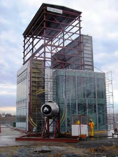
-   Resistance to water penetration: Resistance to water penetration performance requirements will vary
    depending on the building’s height, geographic location and exposure classification. In the United
    States, the resistance to water penetration rating is typically established as a function of the design wind
    pressure. In Canada, the CAN/CSA-A440 Standard includes a user’s guide which recommends minimal
    performance levels for each major Canadian city based on geographic location and installation height.
-   Air leakage resistance: Air leakage resistance performance requirements are often established by local
    building and energy codes and will vary for fixed and operable sections.
-   Condensation resistance: Condensation resistance performance requirements will depend on the
    building’s geographic location and climate conditions as well as the interior hygrothermal design
    conditions and type of building occupancy.

1. Industry Standards
Both the United States and Canada have industry standards which establish stringent performance
requirements and testing methods for windows and curtain walls. In the United States, the American
Architectural Manufacturers Association (AAMA) and the National Fenestration Rating Council (NFRC)
are the primary bodies which regulate the window and curtain wall industry. In Canada, standards for the
performance of windows are established by the Canadian Standards Association (CSA). There is no
industry standard for the performance of curtain walls in Canada. Testing methods to evaluate both
laboratory and field performance is established by the American Society for Testing and Materials (ASTM)
for both the United States and Canada.

The following is a list of the principal industry standards which are commonly used to establish the
laboratory performance criteria for windows and curtain walls in North America.
- AAMA/NWWDA-101: Voluntary Specifications for Windows and Glass Doors
   Primarily outlines laboratory performance requirements with regards to resistance to water penetration,
   air leakage resistance and wind load resistance for windows and glass doors (United States).
- CAN/CSA-A440: Windows
   Primarily outlines laboratory performance requirements with regards to resistance to water penetration,
   air leakage resistance and wind load resistance for windows (Canada).
- AAMA 501: Methods of Test for Metal Curtain Walls
   Primarily outlines laboratory performance requirements with regards to resistance to water penetration,
   air leakage resistance and wind load resistance for metal curtain walls (United States).

     Figure 9: Exterior mock-up         test                         Figure 10: Interior mock-up test
     (AAMA 501) - Air-Ins laboratory.                                (CAN/CSA-A440) - Air-Ins laboratory.

______________________________________________________________________________________
2007 Symposium on Building Envelope Technology                                 Page 4/14
Boston, Massachusetts
-   NFRC 102: Steady-State Thermal Transmittance of Fenestration Systems
    Primarily outlines laboratory performance requirements with regards to thermal performance of
    fenestration products (United States).
-   AAMA 1503: Voluntary Test Method for Thermal Transmittance and Condensation Resistance of
    Windows, Doors and Glazed Wall Sections
    Primarily outlines laboratory performance requirements with regards to thermal performance and
    condensation resistance of windows, doors and glazed wall sections (United States).
-   CSA/A440.2: Energy Performance of Windows and other Fenestration Products
    Primarily outlines laboratory performance requirements with regards to thermal performance and
    condensation resistance of windows and other fenestration products (Canada).

                                                        Figure 11: Environmental test chamber -
                                                        Air-Ins laboratory.

The following is a list of the principal industry standards which are commonly used to establish the field
performance criteria for installed windows and curtain walls in North America.
- AAMA 502: Voluntary Specification for Field Testing of Windows and Sliding Glass Doors
   Primarily outlines field performance requirements with regards to resistance to water penetration and air
   leakage resistance for windows and glass doors (United States).
- AAMA 503: Voluntary Specification for Field Testing of Storefronts, Curtain Walls and Sloped
   Glazing Systems
   Primarily outlines field performance requirements with regards to resistance to water penetration and air
   leakage resistance for Storefronts, Curtain Walls and Sloped Glazing Systems (United States).
- CAN/CSA-A440.4 (appendix D): Field Testing of Window and door Installations
   Primarily outlines field performance requirements with regards to resistance to water penetration and air
   leakage resistance for windows and doors (Canada).

    Figure 12: Field testing for resistance to       Figure 13: Field testing for resistance to
    water penetration.                               water penetration.
______________________________________________________________________________________
2007 Symposium on Building Envelope Technology                                           Page 5/14
Boston, Massachusetts
Field Performance Evaluation
The previous section of this paper highlighted the primary performance requirements and industry
standards related to windows and curtain walls and are intended to provide the reader with some basic
background on the subject, however, the main focus of this paper is the field evaluation of the performance
of installed windows and curtain walls. Given the ever growing complexity and variety of modern building
envelopes, the evaluation of the performance of installed windows and curtain walls in the pre-construction
and construction phase is essential in order to avoid undesirable and costly problems during the service life
of the building.

In most projects of any significance, the performance of the window and curtain wall systems which are to
form part of the building envelope are evaluated in an accredited testing laboratory prior to construction. It
is equally important, however, that the field performance of the installed products be evaluated as a quality
control measure at different phases of construction. Site conditions, variations in the manufacturing process
and the quality and experience of the field installation team are all factors which will impact the
performance of the installed products or systems.

The first step when considering field testing is to identify test areas which are representative of the most
common elements of the building envelope. Typically, field testing is usually limited to three to six test
areas due to budgetary and scheduling constraints. It is therefore very important that the test areas be
carefully selected in order to ensure a good sampling. The test areas should be selected based on the
complexity of any given detail or condition as well as the frequency at which a given detail or condition is
repeated throughout the project. Field testing should always include the interface between the window
and/or curtain wall and the adjacent wall assembly in order to be representative of the entire installation.
This interface is often the most critical element of any installation and may not have been validated by any
form of laboratory testing prior to construction.

 Figure 14, 15 and 16: Identification of representative areas for field testing (precast
 concrete / punch window wall assembly).

______________________________________________________________________________________
2007 Symposium on Building Envelope Technology                                 Page 6/14
Boston, Massachusetts
The test area for metal and glass curtain walls must incorporate all the essential components in order to be
representative. The test area should be at least three glass bays wide as to incorporate a central bay which
incorporates all the junction details. In the case of a unitized curtain wall system, a vertical module joint
should also be included within the test area. The height of the test area should include at least one
expansion or stack joint, at least one spandrel section and one vision section. Typically, the height of the
test area should be at least one full floor storey high. If the curtain wall is installed adjacent to another type
of wall assembly, the interface detail should also be included within the test area.
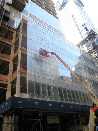
Figure 17: Identification of representative area for field testing
(metal and glass curtain wall).
Figure 18: Identification of representative area for field testing Figure 19: Vertical section illustrating
(metal and glass curtain wall and adjacent masonry assembly). location of test chamber and elements
included in typical curtain field test.
______________________________________________________________________________________
2007 Symposium on Building Envelope Technology Page 7/14
Boston, Massachusetts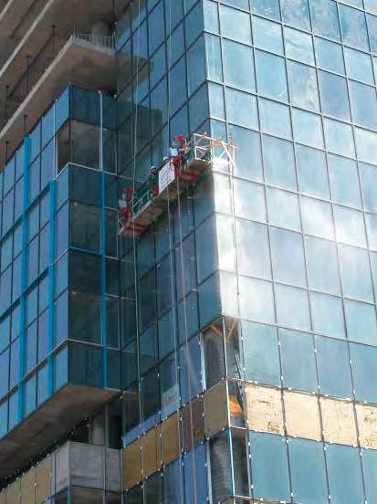
1. Test Methods
The two primary criteria evaluated in the field are air leakage resistance and resistance to water penetration.
The following are the principal standardized test methods used to evaluate these criteria in the field.
- ASTM E783: Field Measurement of Air Leakage Through Installed Exterior Windows and Doors
    Outlines the test method for field measuring air leakage through installed exterior windows and doors.
    This test method is also used for measuring air leakage through curtain wall systems (quantitative test
    method).
- ASTM E1186: Standard Practice for Air Leakage Site Detection in Building Envelope and Air Barrier
    Systems (chamber pressurization in conjunction with white smoke tracers method)
    Outlines the test method to qualitatively assess air leakage through exterior building envelope and air
    barrier systems in the field (qualitative test method).
- ASTM E1105: Field Determination of Water Penetration of Installed Exterior Windows, Curtain Walls
    and Doors by Uniform Static Air Pressure Difference
    Outlines the test method for the field determination of water penetration of installed exterior windows,
    curtain walls and doors.

Regardless of the three test methods noted above, a pressure differential must be created across the test
specimen in order to simulate wind pressure. In order to create the required pressure differential, a test
chamber is typically erected on the interior side of the test specimen. When exterior access is difficult, such
as in the case of skylights, the test chamber can be erected on the exterior side of the test specimen. In
certain cases, it may be possible to use high-power blower doors installed within a confined space. This
method, however, is typically only used for forensic testing in occupied buildings. For new construction or
major renovation projects, a minimum of three tests sequences should be foreseen as a quality control
measure - at the very beginning of the project, midway through the project and near the end of the project.

 Figure 20: Interior test chamber used to test a               Figure 21: Interior test chamber used to test a
 portion of curtain wall section.                              punch window assembly

 Figure 22: Exterior test chamber used to test a               Figure 23: High power blower door installed
 skylight section.                                             within a confined space adjacent to an exterior wall.

______________________________________________________________________________________
2007 Symposium on Building Envelope Technology                                 Page 8/14
Boston, Massachusetts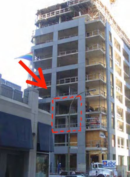
The test pressures are typically specified by the project architect and are different for the air
infiltration/exfiltration test and the water penetration test. The air infiltration/exfiltration test is typically
undertaken at a pressure differential of 1.57 psf (75 Pa) or 6.24 psf (300 Pa). The water penetration test is
undertaken at pressure differentials varying between 6 psf (290 Pa) and 14.6 psf (700 Pa). The following
table provides the wind speed equivalences for different pressure differentials.

                         Pa              kph              psf           in.H2O            mph
                     75 Pa           40 kph           1.57 psf       0.30’’H20        25 mph
                    137 Pa           54 kph           2.86 psf       0.55’’H20        34 mph
                    144 Pa           56 kph           3.00 psf       0.58’’H20        35 mph
                    150 Pa           57 kph           3.13 psf       0.60’’H20        35 mph
                    180 Pa           62 kph           3.75 psf       0.72’’H20        39 mph
                    200 Pa           66 kph           4.17 psf       0.80’’H20        41 mph
                    216 Pa           68 kph           4.50 psf       0.87’’H20        42 mph
                    252 Pa           74 kph           5.25 psf       1.01’’H20        46 mph
                    288 Pa           79 kph           6.00 psf       1.15’’H20        49 mph
                    299 Pa           80 kph           6.24 psf       1.20’’H20        50 mph
                    300 Pa           80 kph           6.26 psf       1.20’’H20        50 mph
                    324 Pa           83 kph           6.75 psf       1.30’’H20        52 mph
                    360 Pa           88 kph           7.50 psf       1.44’’H20        55 mph
                    383 Pa           90 kph           8.00 psf       1.53’’H20        56 mph
                    384 Pa           91 kph           8.00 psf       1.54’’H20        56 mph
                    396 Pa           92 kph           8.25 psf       1.59’’H20        57 mph
                    400 Pa           93 kph           8.34 psf       1.61’’H20        58 mph
                    431 Pa           96 kph           9.00 psf       1.73’’H20        60 mph
                    467 Pa          100 kph           9.75 psf       1.88’’H20        62 mph
                    500 Pa          104 kph          10.43 psf       2.01’’H20        64 mph
                    503 Pa          104 kph          10.50 psf       2.02’’H20        65 mph
                    539 Pa          108 kph          11.25 psf       2.17’’H20        67 mph
                    575 Pa          111 kph          12.00 psf       2.31’’H20        69 mph
                    600 Pa          114 kph          12.51 psf       2.41’’H20        71 mph
                    700 Pa          123 kph          14.60 psf       2.81’’H20        76 mph
                    750 Pa          127 kph          15.64 psf       3.01’’H20        79 mph
                  Figure 24: Table of wind speed equivalences.

2. Air Infiltration/Exfiltration Test
As previously noted, air leakage testing is typically undertaken at a pressure differential of 1.57 psf (75 Pa)
or 6.24 psf (300 Pa). In the United States, the AAMA 502 standard provides guidelines for allowable air
leakage rates of installed windows and sliding glass doors. In accordance with the AAMA 502, allowable
rates of air leakage for field testing shall be 1.5 times the applicable laboratory test rating, unless otherwise
specified (see table below).

Figure 25: Example of allowable air leakage rates depending on window classification (source: AAMA 502-02).

______________________________________________________________________________________
2007 Symposium on Building Envelope Technology                                 Page 9/14
Boston, Massachusetts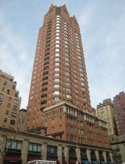
In Canada, the CSA A440.4 standard provides guidelines for allowable air leakage rates of installed
windows, tested at a pressure differential of 1.57 psf (75 Pa), as outlined in the table below.

  Figure 26: Allowable air leakage rates depending on window classification (source: CSA A440.4-07).

When it comes to metal and glass curtain walls, the allowable air leakage rates are typically indicated in the
architectural specifications and will vary depending on local building and energy codes and will also vary
for fixed and operable sections.

The field air leakage resistance test consists of sealing a chamber to cover the interior or exterior face of the
specimen to be tested, supplying air to or exhausting air from the chamber at a rate required to maintain the
specified test pressure difference across the specimen, and measuring the resultant air flow through the
specimen.

                     Figure 27: Typical set-up for field air leakage resistance test (source: CSA A440.4).
______________________________________________________________________________________
2007 Symposium on Building Envelope Technology                                Page 10/14
Boston, Massachusetts
It is important to note that obtaining accurate air leakage results in the field is often difficult, particularly
with curtain wall assemblies. Test results should be questioned when extraneous air leakage from either the
test chamber and/or the confines of the test specimen significantly exceeds the allowable air leakage for the
test specimen. Where it is not practical or possible to quantify air leakage, smoke exfiltration testing is an
excellent alternative which can be used to qualify an air leakage problem. The smoke exfiltration test is
undertaken by applying a uniform positive static pressure differential of 1.57 psf (75 Pa) across the test
specimen and filling the test chamber with white smoke, using a portable smoke generator. The test consists
of checking for any visible excessive smoke exfiltration from the exterior side of the test specimen.
Figure 28: Portable smoke generator used to fill Figure 29: Excessive smoke exfiltration visible on
test chamber with white smoke. exterior side of curtain wall test specimen.
3. Water Penetration Test
The field water penetration resistance test consists of sealing a chamber to the interior or exterior face of
the test specimen to be tested, supplying or exhausting air to the chamber at the rate required to maintain
the desired air pressure difference across the test specimen. Simultaneous to the application of air pressure
difference, water shall be applied to the exterior face of the test specimen at the required rate (5 gal
US/h/ft²) while observing for any water penetration at the interior.
Figure 30: Typical set-up for field water penetration test (source: AAMA 503).
______________________________________________________________________________________
2007 Symposium on Building Envelope Technology Page 11/14
Boston, MassachusettsIn the United States, the AAMA 502 standard provides guidelines for allowable water penetration
resistance ratings of installed windows and sliding glass doors. In accordance with the AAMA 502
standard, water penetration resistance tests shall be conducted at a static test pressure equal to 2/3 of the
applicable laboratory test rating, unless otherwise specified. In Canada, there is no provision in the CSA
A440.4 standard for reduction in the field testing pressure.
For the water penetration resistance field test, a calibrated sprinkler rack is hung on the exterior side of the
test specimen in order to apply a continuous and uniform water spray. It is important that sufficient water
pressure is available on site in order to ensure that the required amount of water is sprayed on the entire
specimen. When sufficient water pressure is not available on site, the use of a portable water reservoir and
pump system may be necessary.
It is also important that the exterior temperatures be above freezing in order to run a water test. When
undertaking a water test in winter conditions, a temporary heated enclosure should be installed on the
exterior side of the test specimen.
Figure 31: Calibrated sprinkler rack Figure 32: Calibrated sprinkler rack
hung from suspended scaffolding. hung from motorized man lift.
Figure 33: Portable water reservoir and pump Figure 34: Temporary exterior heating via test
system. specimen.
______________________________________________________________________________________
2007 Symposium on Building Envelope Technology Page 12/14
Boston, Massachusetts4. Other Diagnostic Tools Depending on specific applications, a variety of other diagnostic tools can be used to assess the performance of the vertical building envelope, whether as a quality control measure or for forensic purposes. For example, when attempting to pin point a specific water infiltration problem, the AAMA 501.2 entitled Quality Assurance and Diagnostic Water Leakage Field Check of Installed Storefronts, Curtain Walls, and Sloped Glazing Systems can be used. Infrared thermography is also used extensively in the building construction industry as a quality control and forensic tool to assess air leakage performance and the presence of moisture in exterior wall assemblies, in accordance with the CAN/CGSB 149-GP-2MP standard entitled Manual for Thermographic Analysis of Building Enclosures. Figure 35: Diagnostic hose testing of curtain wall Figure 36: Diagnostic hose testing window/wall section. interface. Figure 37: Thermographic image of excessive air Figures 38 and 39: Thermographic image of leakage at the interface of the curtain wall with the excessive air leakage at the perimeter of the adjacent wall assembly. fenestration system. ______________________________________________________________________________________ 2007 Symposium on Building Envelope Technology Page 13/14 Boston, Massachusetts
Summary and Conclusion

Any form of water infiltration to the interior side of a building, excessive air leakage resulting in: 1)
discomfort to building occupants; 2) the formation of excessive condensation on the interior side of the
building or 3) the formation of icicles on the exterior side of the building, would be unacceptable to any
building owner or occupant. This being said, one of the primary performance criteria for any window or
curtain wall system is that they provide an appropriate level of resistance to water penetration and air
leakage resistance.

In most projects of any significance, the performance of the window and curtain wall systems which are to
form part of the building envelope are evaluated in an accredited testing laboratory prior to construction. It
is equally important, however, that the field performance of the installed products be evaluated as a quality
control measure at different phases of construction. Site conditions, variations in the manufacturing process
and the quality and experience of the field installation team are all factors which will impact on the
performance of the installed products or systems.

The first step when considering field testing is to identify test areas which are representative of the most
common elements of the building envelope. The test areas should be selected based on the complexity of
any given detail or condition as well as the frequency at which a given detail or condition is repeated
throughout the project. Field testing should always include the interface between the window and/or curtain
wall and the adjacent wall assembly in order to be representative of the entire installation. This interface is
often the most critical element of any installation and may not have been validated by any form of
laboratory testing prior to construction.

For new construction or major renovation projects, a minimum of three tests sequences should be foreseen
as a quality control measure - at the very beginning of the project, midway through the project and near the
end of the project.

                                  References and Additional Reading

1.   Canada Mortgage and Housing Corporation, ‘‘Best Practice Guide - Glass and Metal Curtain Walls’’,
     2004.
2.   Quirouette, R.L., ‘‘Building Envelope Design using Metal and Glass Curtain Wall Systems’’, Building
     Practice Note, Division of Building Research, National Research Council Canada, September 1982.
3.   Gonçalves, M., Gendron, P., Colantionio, T., ‘‘Commissioning of Exterior Building Envelopes of
     Large Buildings for Air Leakage and Resultant Moisture Accumulation using Infrared Thermography
     and Other Diagnostic Tools’’, Thermal Solutions 2007, Sarasota, Florida.

______________________________________________________________________________________
2007 Symposium on Building Envelope Technology                                Page 14/14
Boston, Massachusetts
You can also read