FCC-ee Machine Detector Interface study - CERN Indico
←
→
Page content transcription
If your browser does not render page correctly, please read the page content below
FCC-ee Machine Detector Interface study
 ABP Info Meeting, 11 February 2021

 Manuela Boscolo, INFN-LNF & CERN

 on behalf of FCC-ee MDI group
 special thanks to Michael Benedikt and Frank Zimmermann
LHC
 PS

 SPS FCC

 http://cern.ch/fcc

Work supported by the European Commission under the HORIZON 2020 projects
EuroCirCol, grant agreement 654305; FCCIS, grant agreement 951754
 photo: J. Wenninger
from ESPPU 2020 document

Core sentence and main request “order of the further FCC study”:

“Europe, together with its international partners, should investigate the
technical and financial feasibility of a future hadron collider at CERN with a
centre-of-mass energy of at least 100 TeV and with an electron-positron
Higgs and electroweak factory as a possible first stage. Such a feasibility
study of the colliders and related infrastructure should be established as a
global endeavour and be completed on the timescale of the next Strategy
update.”

Future Circular Collider Study
Manuela Boscolo
ABP Info Meeting, 11 February 2021
FCC roadmap
 >2030 >2036
 start tunnel machine
 construction installation
 >2040 first
 2028 approval
 ee collisions
 2026/7 >2030 - 37
 ESPPU element production
 2025/26 >2026 - 30 full
 technical design
 2014 FCC Feasibility proof
 study kickoff 2020 FCCIS 2025/26
 2018 FCC CDR kickoff Financing model
 2013
 ESPPU Operation concept

 2012 Higgs
discovery announced 2020 today
 2020 2025
 ESPPU FCC Feasibility Study
 2011 circular Higgs factory proposal FCCIS H2020 DS
 Future Circular Collider Study
 Manuela Boscolo
 ABP Info Meeting, 11 February 2021
FCC-ee basic design choices
double ring e+e- collider ~100 km K. Oide et al.
follows footprint of FCC-hh, except around IPs
crab-waist optics [ArXiv.070233]
large horizontal crossing angle 30 mrad
asymmetric IR optics to limit synchrotron radiation
towards the detector
presently 2 IPs (alternative layouts with 3 or 4 IPs under
study)
synchrotron radiation power 50 MW/beam at all beam
energies; tapering of arc magnet strengths to match local
energy
common RF for ҧ running
top-up injection requires booster synchrotron in collider tunnel

 Future Circular Collider Study FCC-ee: The Lepton Collider, Eur. Phys. J. Spec. Top. 228, 261–623 (2019)
 Manuela Boscolo
 ABP Info Meeting, 11 February 2021 K. Oide et al., Phys. Rev. Accel. Beams 19, 111005 (2016)
FCC-ee basic design choices
double ring e+e- collider ~100 km K. Oide et al.
follows footprint of FCC-hh, except around IPs
crab-waist optics [ArXiv.070233] great
large horizontal crossing angle 30 mrad impact on
 the MDI
asymmetric IR optics to limit synchrotron radiation
 layout!
towards the detector

SR is one of the main drivers of the MDI design:
• requirement Ecritical < 100 keV for incoming beam from
 500 m to IP (based on LEP experience)
• Different countermeasures to cope with its impact in
 the MDI area

 Future Circular Collider Study FCC-ee: The Lepton Collider, Eur. Phys. J. Spec. Top. 228, 261–623 (2019)
 Manuela Boscolo
 ABP Info Meeting, 11 February 2021 K. Oide et al., Phys. Rev. Accel. Beams 19, 111005 (2016)
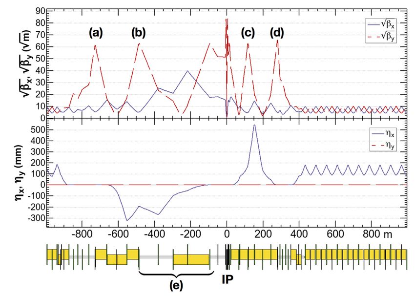
Interaction Region optics
 Final Focus optics
 ttbar 182.5 GeV
 Z-pole
 Ebeam = 45.6 GeV
 Only first slice of QC1 is
 defocusing horizontally

 QC2 QC1 QC1 QC2

 ҧ
 Ebeam = 182.5 GeV

 All three slices of QC1 are
 defocusing horizontally
 yellow boxes:
 dipole magnets QC2 QC1 QC1 QC2

Asymmetric optics suppresses SR toward the IP,
 Flexible optics design:
 Ecritical
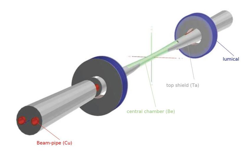
FCC-ee MDI Layout
 Baseline, updated picture (SR masks) 1 cm radius central chamber

Not shown in the above layouts, for the detector solenoid compensation scheme:
screening solenoid shields the detector field inside the quads
compensating solenoid in front of the first quad to reduce the ey blow-up IP

 Future Circular Collider Study
 Manuela Boscolo
 ABP Info Meeting, 11 February 2021
FCC-ee MDI study • MDI/IR engineering design and mechanical layout with integration • Backgrounds study (SR, single and IP bkgs, sustainability by the detector, shieldings, top-up injection bkg,..) → Related to the MDI layout design: masks, shieldings, collimators → Related to optics design, with requirements especially to dynamic aperture, energy acceptance → Beam-beam and beamstrahlung stability • Luminosity measurement • IR magnets • IR beam diagnostics and IP detectors • Alignment tolerances & vibration control tight tolerances for alignment of magnets, very good orbit stability and vibrations control required • IR heat load assessment Different areas of activity with various expertise required: accelerator and experimental physics, engineering, technology Future Circular Collider Study Manuela Boscolo ABP Info Meeting, 11 February 2021
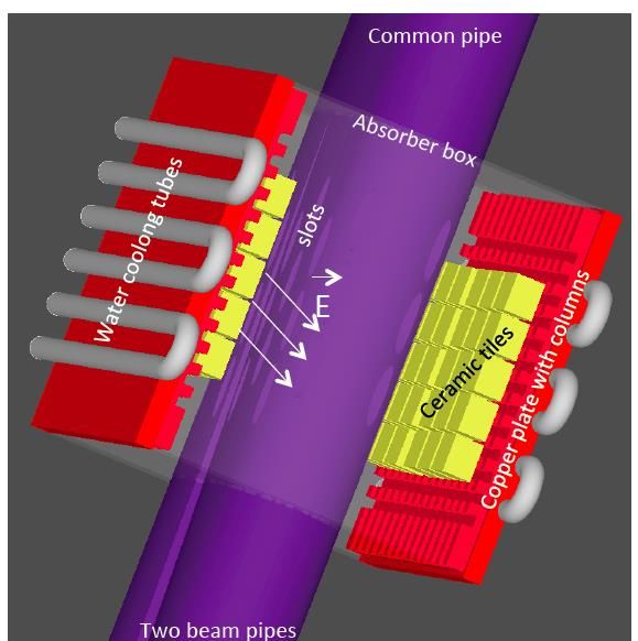
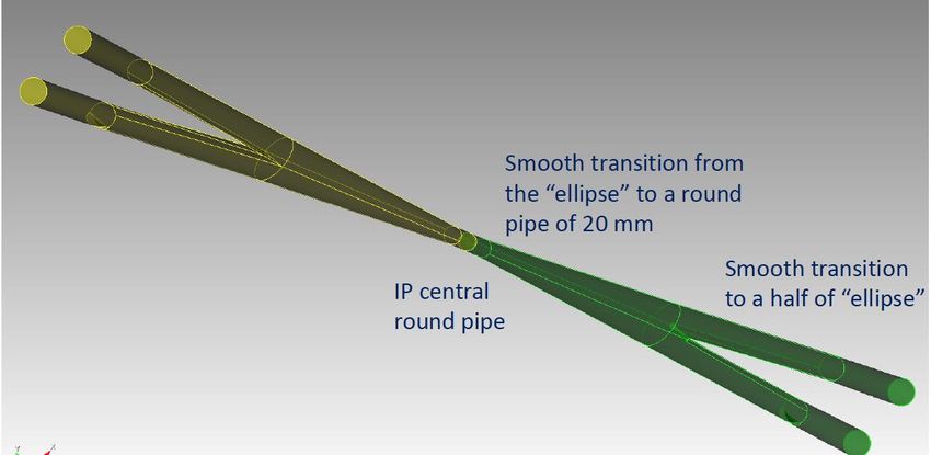
IR beam pipe model (CDR)

The incoming pipes and the central beam pipe have the same Higher Order Modes absorber
diameter of 30 mm
Special transition from two beam pipes to a common central pipe.

HOM absorbers are necessary, they are described in
Ref. [A. Novokhatski et al. PR-AB 20, 111005 (2017)]
They are based on the property of the trapped modes, following the PEP-II experience.

 The absorber vacuum box is placed around the beam pipe connection. Inside the box we have ceramic
 absorbing tiles and copper corrugated plates. The beam pipe in this place has longitudinal slots, which
 connect the beam pipe and the absorber box. Outside the box we have stainless steel water-cooling
 tubes, braised to the copper plates. The HOM fields, which are generating by the beam in the
 Interaction Region pass through the longitudinal slots into the absorber box. Inside the absorber box
 these fields are absorbed by ceramic tiles, because they have high value of the loss tangent. The heat
 from ceramic tiles is transported through the copper plates to water cooling tubes.

 Future Circular Collider Study
 Manuela Boscolo
 ABP Info Meeting, 11 February 2021
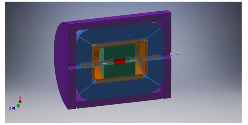
IR beam pipe model
Recently, a new study with a smaller central beam pipe model was performed [L. Pellegrino, FCCWEEK2020]

The model was used for wakefield calculations showing the great advantage that HOM absorbers are no longer
required. [A. Novokhatski, FCCWEEK2020]
 smaller central chamber, radius=1.0 cm
The impact on synchrotron radiation in the
central chamber has been checked finding
acceptable values. [M. Sullivan, FCCWEEK2020]

First studies performed by the detector group
are encouraging.
More studies are are planned.

 Future Circular Collider Study
 Manuela Boscolo
 ABP Info Meeting, 11 February 2021
Backgrounds Studies
 Requirement of developing
• Synchrotron radiation background and updating software tools
 • different codes used, complementary with each other (MDISim, Synch_bkg, SynRad+)
 and impact on detector investigated
• Generation of background sources
 • IP backgrounds
 • Single beam backgrounds:
• Tracking beam scattered particles
 • IR loss map → and track into detectors
 • loss maps around the ring → for collimation study
 • Multiturn tracking for IP and single beam bkgs
 • Collimation scheme
 • Beam tails Geant4 model for the detector
 backgrounds studies (CDR)

 Future Circular Collider Study
 Manuela Boscolo
 ABP Info Meeting, 11 February 2021
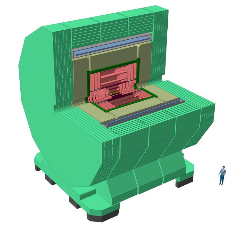
13

 FCC-ee Detectors
 CLD Detector IDEA detector
 adaptation of the CLIC proposed by INFN, also for CEPC
 detector model (2T)
 Silicon-based vertex and
 tracking detectors
 ILCSoft

 Impact of background in detectors found manageable
 evaluated: SR (with Ta shielding), Beamstrahlung, Incoherent Pair Production at CLD, gg
 to hadrons, Radiative bhabhas, Beam-gas
 → This study is in progress with a refined G4 model, and with more bkgs simulation, i.e.
 with the spent beam particles, ...

 Future Circular Collider Study
 Manuela Boscolo
 ABP Info Meeting, 11 February 2021
Synchrotron Radiation collimators
 Ref. MDISim

 Negligible effects on IP

 Last bending magnets
 Z [m]
 @ 200m from IP
 Collimators position
 Z [m]

 Contribution from various SR mask
 groups of dipoles
 Zoom near the IP

 M. Luckof

Future Circular Collider Study
Manuela Boscolo
ABP Info Meeting, 11 February 2021
Single beam backgrounds:
 beam-gas bremsstrahlung
MDISim used to import in Geant4 Loss Rates
 link: MOPMF085, IPAC18
 IR Loss map
 longit. position, origin of BG
 beam interactions that will lead to
 particle loss

 FCC-ee Loss rate Loss Rate
 indipendent simulation based on MAD-X
 energy [-800;+200] m [-20;+20] m particle tracking link
 from IP [MHz] from IP [MHz]
 Z 147 29 tracked into lumical
 W 16 3
 • Very good agreement between the two indipendent simulation codes
 H 3 0.5
 t 0.5 0.1
 • Plan to use realistic pressure density plots, and continue this study

 Future Circular Collider Study
 Manuela Boscolo
 ABP Info Meeting, 11 February 2021
Single beam backgrounds: Thermal photons First described in 1987 by V. Telnov , main single beam lifetime limitation in LEP, well measured and simulated using the algorithm described in SL/Note 93-73 [H. Burkhardt, FCC WEEK2019] Loss map@ttbar lost particles energy spectrum Thermal g 31.2 0.5 |s|
FCCIS WP2 FCC-ee Collider Design
Task 2.1: Work package coordination – Ilya Agapov (DESY), deputy Frank Zimmermann (CERN)
(lead: DESY, participants: CEA, CERN, CNRS, KIT, IFJPAN, INFN)

Task 2.2: Collider design (lead: DESY, participants: CEA, CERN, CNRS, KIT, IFJPAN, INFN, partner BINP)

Task 2.3: Interaction region and machine detector interface design (lead: INFN, participants: CERN, CNRS, DESY, partners BINP and UOXF)

Task 2.4: Full energy booster and top-up injection design (lead: CEA, participants: CERN, INFN, BINP)

Task 2.5: Polarisation and energy calibration (lead: KIT, participants: CERN, partner BINP)

WP2: Beam Tests (CERN, DESY, INFN, KIT, BINP, UOX, PSI, KEK)
facilities: KARA, DAFNE, PETRA III, VEPP-4M, SuperKEKB

 M2.1 MS4 Milestone Product Break- down Structure 01/07/2021
 D2.1 D4 Deliverable Performance, optics and design baseline 01/11/2021
 D2.2 D5 Deliverable IR & MDI design 01/07/2023
 D2.3 D6 Deliverable Full-energy booster design 01/03/2024
 D2.4 D7 Deliverable Experimental characterisation of key enablers 01/05/2024
 D5.6 D21 Deliverable (WP5) FCC-ee design report 01/11/2024
 Future Circular Collider Study
 Manuela Boscolo
 ABP Info Meeting, 11 February 2021
Conclusion

• The Machine Detector Interface study is a key topic for the success of FCC-ee

• Many exciting challenges for the design with state-of-the art technologies and
 experience on past and present colliders

• Many interesting topics to be studied in the coming years !

 FCC-ee MDI regular meetings indico page: https://indico.cern.ch/category/5665/

 Future Circular Collider Study
 Manuela Boscolo
 ABP Info Meeting, 11 February 2021
spare slides
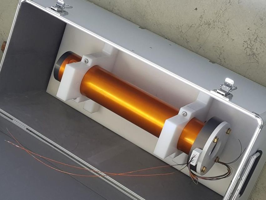
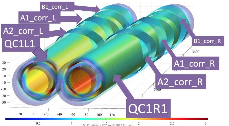
Final Focus Quadrupole
CCT (canted cosine theta) concept
No iron

 M. Koratzinos
 First prototype FF quad is ready for
 warm testing by the TE-MSC-MM team

 prototype during construction
 20
 M.Boscolo, FCC November week 2020
H2020 DS FCC Innovation Study 2020-24
 Topic INFRADEV-01-2019-2020
 Grant Agreement FCCIS 951754
 Duration 48 months
 From-to 2 Nov 2020 – 1 Nov 2024
 Project cost 7 435 865 €
Beneficiaries
 EU contribution 2 999 850 €
 Beneficiaries 16
 Partners 6

 Partners

 Future Circular Collider Study
 Manuela Boscolo
 ABP Info Meeting, 11 February 2021
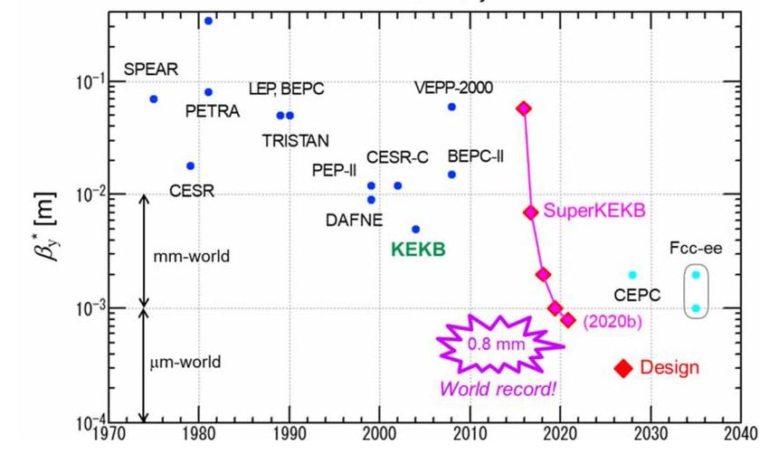
SuperKEKB – pushing luminosity and b*
Design: double ring e+e- collider as B-factory at 7(e-) & 4(e+) GeV; design luminosity ~8 x 1035 cm-2s-1; by* ~ 0.3 mm;
nano-beam – large crossing angle collision scheme (crab waist w/o sextupoles); beam lifetime ~5 minutes; top-up injection;
e+ rate up to ~ 2.5 1012 /s ; under commissioning

 M. Tobiyama, K. Oide

 SuperKEKB is
 demonstrating FCC-ee
 key concepts

 by* = 0.8 mm achieved in both rings – using the
 Y. Funakoshi, Y. Ohnishi, K. Oide FCC-ee-style “virtual” crab-waist collision scheme
 Future Circular Collider Study
 Manuela Boscolo
 ABP Info Meeting, 11 February 2021
FCC-ee Collider Parameters
parameter Z WW H (ZH) ttbar
beam energy [GeV] 45 80 120 182.5
beam current [mA] 1390 147 29 5.4
no. bunches/beam 16640 2000 393 48
bunch intensity [1011] 1.7 1.5 1.5 2.3
SR energy loss / turn [GeV] 0.036 0.34 1.72 9.21
total RF voltage [GV] 0.1 0.44 2.0 10.9
long. damping time [turns] 1281 235 70 20
horizontal beta* [m] 0.15 0.2 0.3 1
vertical beta* [mm] 0.8 1 1 1.6
horiz. geometric emittance [nm] 0.27 0.28 0.63 1.46
vert. geom. emittance [pm] 1.0 1.7 1.3 2.9
bunch length with SR / BS [mm] 3.5 / 12.1 3.0 / 6.0 3.3 / 5.3 2.0 / 2.5
luminosity per IP [1034 cm-2s-1] 230 28 8.5 1.55
beam lifetime rad Bhabha / BS [min] 68 / >200 49 / >1000 38 / 18 40 / 18
FCC integrated project technical schedule
1 2 3 4 5 6 7 8 9 10 11 12 13 14 15 16 17 18 15 years operation 34 35 36 37 38 39 40 41 42 43 ~ 25 years operation 70

 Update
 Project preparation & Permis-
 Permis
 administrative processes sions
 sions
 Funding and Funding and
 Funding in-kind in-kind
 strategy contribution contribution
 agreements agreements
 Geological investigations, FCC-ee dismantling, CE
 Tunnel, site and technical infrastructure
 infrastructure detailed design and & infrastructure
 construction
 tendering preparation adaptations FCC-hh

 FCC-hh accelerator
 FCC-ee accelerator construction, FCC-hh accelerator construction,
 FCC-ee accelerator R&D and technical design R&D and technical
 installation, commissioning installation, commissioning
 design

 Set up of international
 FCC-hh detector FCC-hh detector
 experiment collaborations, FCC-ee detector FCC-ee detector
 R&D, construction, installation,
 detector R&D and concept technical design construction, installation, commissioning
 technical design commissioning
 development

 16 T magnet
 Long model magnets,
 Superconducting wire and magnet R&D, short models industrialization and
 prototypes, preseries
 series production

 Future Circular Collider Study
 Manuela Boscolo
 ABP Info Meeting, 11 February 2021
Summary of SR in the IR with smaller central chamber

 • We have looked at changing the central beam pipe radius from 15 mm
 to 10 mm and shortening the Z length from 25 cm to 18 cm
 • The new beam pipe now intercepts SR from the FF quadrupoles and
 also intercepts bend radiation from the last soft bend before the IP
 • The bend radiation can be masked away by reducing the mask radius at
 -2.1 m from 10 mm to 7 mm
 • The quadrupole radiation cannot be totally masked away even with a 5
 mm radius mask at -2.1 m
 • A smaller beam pipe for the Z running looks possible
 • A 1 cm radius beam pipe for the ZH running is more
 problematic but with careful design work should be possible
 • The detector occupancy will be higher – may be still OK?
 • The IR design becomes more sensitive to the high sigma beam tail
 distributions
 • This also means that the IR design is more sensitive to b* changes
 in the machine lattice
Future Circular Collider Study
Manuela Boscolo
ABP Info Meeting, 11 February 2021
Heat load for 30 mm beam pipe

 bunch length [mm] HEAT LOAD Two beams [W/m] current [A] Bunch spacing [ns]
 2 x 1.39 19.50

 12.10 63.45 69.18 81.68 96.57 125.23 349.64 1473.91
 Material Cu Au Al Be Ni SS NEG

• Beryllium pipe takes 100 W/m for a
 12 mm bunch but strongly increasing
 with shortening the bunch length.
• A gold coating can decrease the heat
 load by 30%

 A. Novokhatski

 Future Circular Collider Study
 Manuela Boscolo
 ABP Info Meeting, 11 February 2021
Beamstrahlung
• SR in field of opposing beam, estimated at the Z with Guinea-Pig
• The IR will generate a very significant flux and power of hard X-rays
 lost mostly in the first downstream bend (49-55 m from IP)

 Power
 Classical SR and Guinea-Pig
 keV KW
 IP magnets (quad, solenoid) 1.3 24 43 kW (also without collisions)
 Beamstrahlung 0.15 2000 417 kW photon energies extend
 into the GDR region

 • ~460 kW hitting in a narrow ~5 m wide region
 • wall power / length of order 100 kW/m

 some MW / IP with spectrum extending into tenths of MeV
 strongly varying with bb-parameters and residual separation H. Burkhardt

 Future Circular Collider Study
 Manuela Boscolo
 ABP Info Meeting, 11 February 2021
Radiative Bhabha

• BBBrem has been implemented in SAD
• Beam loss due to radiative Bhabha for FCC-ee at the Z:
 o 4 kW by 400 m downstream the IP
 o 150 W within the first quad QC1
• The effect of beam-beam is about 20% on the loss at QC1.
• The result is neither sensitive to the misalignment of
 aperture at QC1, nor to the IP solenoid field.

• The tolerance of the final quadrupole for such amount of
 beam loss must be examined.
• Cross check with other method is necessary and in progress.
 K. Oide
 Future Circular Collider Study
 Manuela Boscolo
 ABP Info Meeting, 11 February 2021
You can also read