Improving efficiency and lowering operating costs of evaporative cooling
←
→
Page content transcription
If your browser does not render page correctly, please read the page content below
MATEC Web of Conferences 338, 01027 (2021) https://doi.org/10.1051/matecconf/202133801027
PRMR 2021

 Improving efficiency and lowering operating
 costs of evaporative cooling
 Jan Taler1*, Bartosz Jagieła2, and Magdalena Jaremkiewicz1
 1Cracow University of Technology, Department of Power Engineering, Al. Jana Pawla II 37, 31-864
 Cracow
 2Cracow University of Technology, Department of Thermal Processes, Air Protection, and Waste

 Utilisation S-5, ul. Warszawska 24, 31-155 Cracow

 Abstract. Cooling towers, or so-called evaporation towers, use the natural
 effect of water evaporation to dissipate heat in industrial and comfort
 installations. Water, until it changes its state of aggregation, from liquid to
 gas, consumes energy (2.257 kJ/kg). By consuming this energy, it lowers the
 air temperature to the wet-bulb temperature, thanks to which the medium
 can be cooled below the ambient temperature. Evaporative solutions are
 characterized by continuous water evaporation (approx. 1.5% of the total
 water flow) and low electricity consumption (high EER). Evaporative
 (adiabatic) cooling also has a positive effect on the reduction of electricity
 consumption of cooled machines. Lowering the relative humidity (RH) by
 approx. 2% lowers the wet-bulb temperature by approx. 0.5°C, which
 increases the efficiency of the tower, operating in an open circuit, expressed
 in kW, by approx. 5%, while reducing water consumption and treatment
 costs. The use of the M-Cycle (Maisotsenko cycle) to lower the temperature
 of the wet thermometer to the dew point temperature will reduce operating
 costs and increase the efficiency of cooled machines.

 Keywords: M-Cycle; evaporation tower; cooling tower; adiabatic; IEC; Indirect Evaporative Cooling;
 DEC; Direct Evaporative Cooling; dew point cooling

 1 Introduction
 Polish industry sectors are responsible for approx. 40% of energy consumption, i.e. 65 TWh
 (data from the Central Statistical Office for 2019 [1]). An estimated half of this power is used
 for thermal processes (including pumps, compressors, fans, etc…). Lowering this value can
 be achieved by modernizing worn-out installations or building new energy-saving ones,
 using the best available techniques [2].
 All industrial sectors, such as air conditioning, refrigeration and power production, emits
 heat. Some of this energy can be recovered and reused, e.g. for heating of water. The
 remainder of the useless heat must be dissipated due to its contents low amount of energy.
 Industrial cooling are systems in which excess heat is removed from the medium (water,

 * Corresponding author: bartosz.jagiela@doktorant.pk.edu.pl

© The Authors, published by EDP Sciences. This is an open access article distributed under the terms of the Creative Commons
Attribution License 4.0 (http://creativecommons.org/licenses/by/4.0/).
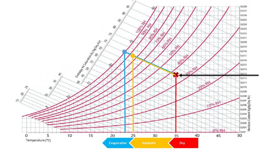
MATEC Web of Conferences 338, 01027 (2021) https://doi.org/10.1051/matecconf/202133801027
PRMR 2021

 glycol, refrigerant, etc.) while reducing its temperature to the ambient temperature. Most
 often, heat is utilized with water and/or air to the outside environment.

 Fig. 1. Energy flow in industry processes [3].
 A cooling system should be designed and applied in a way that will ensure appropriate
 technological conditions, start-up, operation and stoppage of the machines most effectively
 and durably. Local factors limit design possibilities. Such factors include climate, water
 availability, space available for structures, and the location and related restrictions, such as
 noise emissions or environmental pollution.
 One of the most important factors is the local climate as it directly affects the final
 temperature of the medium or air used as a coolant. Refrigeration equipment is designed so
 that the maximum cooling capacity is achieved under the most unfavourable environmental
 conditions. These temperatures are the dry thermometer and the wet thermometer, which
 depends on the air humidity.
 Depending on which temperature, wet or dry, we design a cooling system, we distinguish
 between dry and wet cooling, also known as evaporative cooling. Additionally, one can
 distinguish between adiabatic and hybrid cooling, a combination of dry and wet cooling.
 The psychometric graph shows the reference points for each cooling method, including
 dry cooling in red, evaporative cooling in blue and adiabatic cooling in orange. The arrow
 indicates the initial parameters that are constant for each and are as follows:
 - The temperature of dry-bulb: +35°C,
 - Relative humidity: 35%.

 Fig. 2. Boundaries of each cooling type shown on the psychrometric diagram [3].
 Although conventional air-conditioning (compressor cycle) systems are more likely
 accepted and installed, even of high power consumption, they cover a significant part of the

 2
MATEC Web of Conferences 338, 01027 (2021) https://doi.org/10.1051/matecconf/202133801027
PRMR 2021

 market. Research and developments should not only focus on more effective compressors
 (also other equipment) in terms of power usage. Another point is the impact on our planet.
 Most refrigerants which are used in air-conditioning systems are harmful to the environment
 or people. Most sustainability refrigerant is water. That is why evaporative air-conditioning
 is a really promising technology and should be more likely to use. This paper will investigate
 the potential of using a combination of different evaporative cooling conceptions [4-6].

 2 Energy consumption in a refrigeration cycle
 Direct and indirect energy consumption is an important aspect of designing appropriate
 equipment and complete refrigeration systems. The coefficient of performance (COP) of such
 a system is expressed as the difference between the electricity consumed and the heat
 produced (energy of cooling). The refrigeration systems implement a thermodynamic cycle,
 also the so-called Linde cycle, the efficiency of which is expressed by the pressure difference
 between the evaporator and the condenser.
 To increase efficiency, including the reduction of energy consumption, the pressure
 difference between the condenser and the evaporator should be reduced. In cooling or air-
 conditioning systems, the evaporation temperature of the medium is constant, depending on
 the medium or reservoir being cooled. To lower the condensing pressure, a device that is
 capable to lower the condensing temperature below ambient temperature should be used. An
 example of such a solution is evaporative towers.

 Fig. 3. Caption of the Figure 1. Below the figure.

 3 Evaporative cooling
 Evaporative cooling stands out by high thermal efficiency, thanks to the use of the natural
 effect of water evaporation, with minimal energy consumption and recirculation of approx.
 95% of water. Evaporative technologies are able the process temperature to be reduced below
 ambient temperature (dry thermometer). Compared to dry air cooling, evaporative cooling is
 more effective because 1 kilogram of water can absorb 2.200 kJ of heat (evaporation heat),
 while 1 kilogram of air only approx. 1 kJ per 1 K.

 3
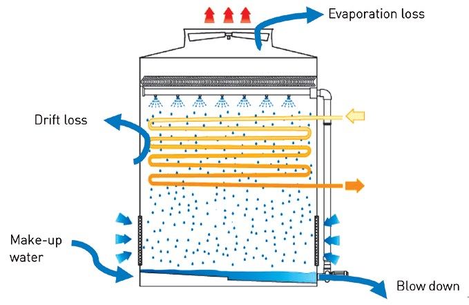
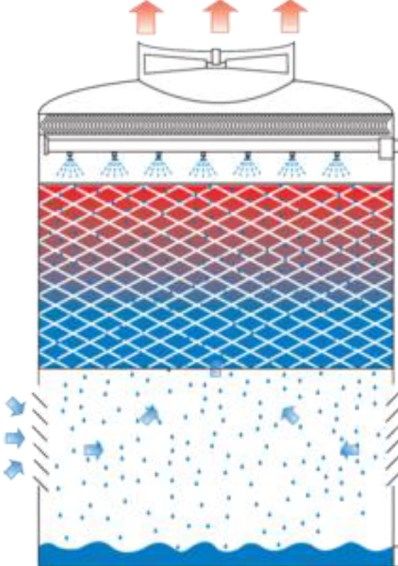
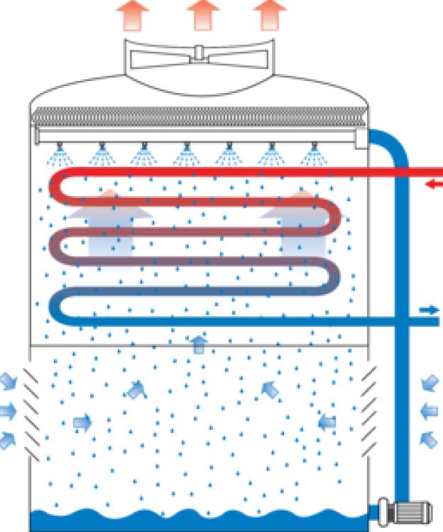
MATEC Web of Conferences 338, 01027 (2021) https://doi.org/10.1051/matecconf/202133801027
PRMR 2021

 (a) (b)

 Fig. 4. Example of (a) open and (b) close cooling tower [7].

 3.1 Water usage

 Cooling towers are characterized by the continuous consumption of water while the device
 is in operation. Contrary to popular knowledge, water consumption does not depend on the
 type of device but external parameters and the quality of water in the circuit. Figure 5 shows
 the water flow balance in a closed evaporation tower.

 Fig. 5. Water balance of close cooling tower [8].
 Main water flows are:
 - Losses:
 - evaporation loss,

 4
MATEC Web of Conferences 338, 01027 (2021) https://doi.org/10.1051/matecconf/202133801027
PRMR 2021

 - drift loss,
 - blowdown,
 - Make-up water.
 The water flow balance, in the cooling tower loop, should be preserved and can be expressed
 as:

 = + + (1)
 Water that is sprinkled on a special filling (air-water channels, open tower) or the
 exchanger (closed tower) evaporates with the airflow. The value of this loss is a few percent
 of the water flow and can be estimated as follows:

 = (2)
 594
 594 – is the mean value of the latent heat of evaporation divided by the specific heat kcal/kg
 water. The real value is related to humidity and the wet-bulb thermometer. This relationship
 is depicted in Figure nr 6.

 Fig. 6. Evaporation losses [8].
 Another loss is blowing down, due to desalination of water (desludging), which is aimed
 at refreshing and restoring the appropriate parameters of the circulating water in the cooling
 tower loop. The exhaust air from the cooler is 100% humid and contains pure H2O. The
 remaining minerals, including salt (conductivity), hardness, chlorides and pH, remain in the
 water basin. With evaporation, the parameters change, increasing their concentration.
 Desalination is aimed at the discharge of such an amount of water that the water parameters
 do not exceed the maximum values for the appropriate materials used in the installation. The
 value of the desalination water discharge depends primarily on the quality of the water and
 the water treatment system used. Knowing the water inlet parameters, an appropriate number
 of concentration cycles can be designed. Having this value determined, the desalination value
 can be calculated from the formula [8]:

 = (3)
 −1
 The aim is to maintain the concentration cycles in the range from 2 up to 4 because
 investment and operating costs above this value are not economical compares to savings.
 The smallest loss in evaporative coolers is the drift loss. In the balance of water
 consumption, practically negligible because drift eliminators are used above the nozzles,
 which reduce drift to approx. 0.001% of the evaporation value.

 5
MATEC Web of Conferences 338, 01027 (2021) https://doi.org/10.1051/matecconf/202133801027
PRMR 2021

 4 Comparison of dry and wet cooling systems
 As indicated above, the use of evaporative coolers will have a positive effect on the efficiency
 of the cooling system with a simultaneously increased effort to keep the equipment in
 operation, in particular, proper water preparation.
 Two refrigeration systems were simulated using CoolPack software [9]. One with an air-
 cooled condenser (dry cooling) and another one with an evaporative condenser (wet cooling).
 To analyse the operation of these refrigeration systems, the following parameters were
 adopted:
 - Refrigerant: R134a
 - Cooling capacity: 1 000 kW
 - Evaporation temperature: +2°C
 - Dry bulb temperature: +35°C
 - Relative humidity: 36%
 - Wet-bulb temperature: +23°C
 - Isentropic efficiency of compression: 0.7

 Fig. 7. Refrigeration cycle with air-cooled condenser [9].

 6
MATEC Web of Conferences 338, 01027 (2021) https://doi.org/10.1051/matecconf/202133801027
PRMR 2021

 Fig. 8. Refrigeration cycle with evaporative condenser [9].
 Figures 7 and 8 show the basic working conditions of each cycle. Most of the parameters of
 the wet cooling system are more favourable than those of the dry one. In particular:
 - Condenser capacity (heating capacity) is approximately 6% lower – condenser could be
 smaller,
 - Compressor input is around 28% lower – energy consumption and size of the compressor
 will be smaller,
 - Mas flow of refrigerant is approximately 10% less – pipes and equipment could be smaller,
 - COP – Coefficient of Performance – higher by 39%.

 5 Direct Evaporation Cooling (DEC)
 As previously indicated, the efficiency of the evaporation system depends on the temperature
 of the dry air and its humidity. The lower the humidity value, the lower the wet-bulb
 temperature, the higher the efficiency of the device. A good case of using water evaporation
 technology is the so-called evaporative air conditioners. On a special panel (cellulose), water
 flows crosswise into the air, which lowers its temperature to the temperature of the wet
 thermometer.
 This type of device is commonly used for direct air cooling, mainly for air conditioning
 large spaces, such as production halls. Evaporators provide fresh and cool air with low energy
 and water consumption. The energy consumption of such a solution is about 85% lower than
 that of air conditioning with compressors.

 7
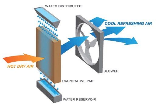
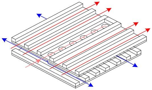
MATEC Web of Conferences 338, 01027 (2021) https://doi.org/10.1051/matecconf/202133801027
PRMR 2021

 Fig. 9. Example of DEC [10].

 6 Indirect Evaporative Cooling – IEC, Maisotsenko Cycle – M-
 Cycle
 The concept of the M-Cycle was created in the seventies in the Soviet Union by Professor
 Valeriy Maisotsenko. In 1976 the first patents were issued (SU979796 and SU620745). Since
 then, the M-Cycle has been used in many applications, most commonly in the USA, which
 are protected by patents, the most important are:US4350570 (1982); US4842052 (1989);
 US4971245 (1990); US4976113 (1990); US4977753 (1990); US5453223 (1995);
 US5812423 (1998); US5838587 (1998); US6497107 (2002); US6581402 (2003);
 US6705096 (2004); US20040103637 (2004); US6776001 (2004); US6779351 (2004);
 US6854278 (2005); US6948558 (2005); US7007453 (2006); US7197887 (2007);
 US7228699 (2007); and US8613839 (2013). Multi-industry solutions were patented,
 including water distillation, power engineering (gas turbines, engines, energy and exergy
 towers) and pollution control (i.e. NOx reduction in gas turbines) [11].
 The most popular solution and commercialized by Coolerado (USA) is the use of the M-
 Cycle for direct cooling of the air. The Maisotsenko cycle is a thermodynamic process that
 absorbs energy from the air, using the psychrometric (air humidity) renewable energy
 available from the latent heat of water evaporating into the air. It combines the
 thermodynamic processes of heat exchange and evaporative cooling to enhance obtaining the
 temperature of the dew point of the air. In other words, the M-Cycle achieves a dew point
 temperature (approx. 18.2°C for parameters from figure 2) which is lower than the wet-bulb
 temperature. Figure 10 shows the difference between DEC and IEC [11]. In Figure 10, the
 following designations have been adopted: Twb – wet-bulb, Tdp – dew point, 1 – inlet air
 conditions, 2 – outlet air conditions, 3 – outlet air conditions of working airflow.
 The principle of operation of M-Cycle is based on paths of dry and wet channels. The
 scheme is shown in figure 11. Cross-flow heat and mass exchanger (HMX) is built of layers
 that are connected each to another forming a “box”.
 Air is divided into two streams, working and product. Each enters a different path.
 Product, so flow which will be cool, is flowing through dry channels. Working flow, which
 will evaporate water, is cooled under constant humidity. No mass is exchanged in dry
 channels. The working stream is entering wet channels precooled, temperature lower than
 ambient, which allows evaporating rest of the water. That activates latent heat which is
 absorbed by dry channels. The product becomes cooler and cooler. Streams at end of the
 channel are 50% of the flows which enters previously.

 8
MATEC Web of Conferences 338, 01027 (2021) https://doi.org/10.1051/matecconf/202133801027
PRMR 2021

 (a) (b)
 Fig. 10. Principle of operation of standard evaporative cooling techniques [11]: (a) DEC, (b) IEC.
 Another benefit that M-Cycle applies is a fact that the product is keeping the same
 humidity. It is achieved by layer construction of HMX and also smart heat and mass transfer
 ratio.

 Fig. 11. Heat and mass exchanging in HMX [12].
 In the paper [12] there was investigated how low temperature can be reached by M-Cycle
 in Mediterranean climate. The region is hotter and more humid than the polish one. It was
 proved that even in high ambient temperature, like +42.1°C, it was possible to reach leaving
 air temperature (+19.2°C) close to dew point (+18.5°C).
 Dew point evaporative cooling have great potential to use it in HVAC technologies. Not
 only indirect cooling of air. One and still not developed is a connection of M-Cycle with the
 evaporative cooling tower. Precooled air leaving M-Cycle can enhance the effectiveness of
 cooling towers in terms of lowering reference temperature from wet-bulb up to dew point. If
 we make an evaluation similar as in figures 7 and 8, but taking into consideration lower
 condensation temperature we will obtain working condition, as shown in Figure 12.

 9
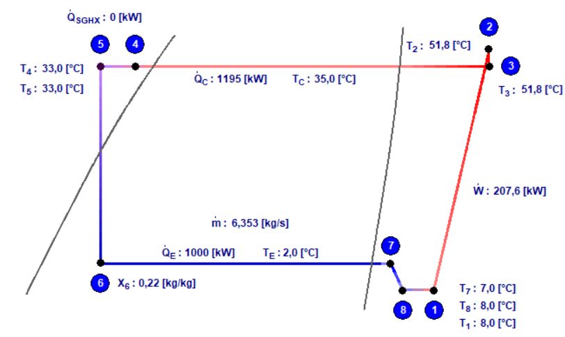
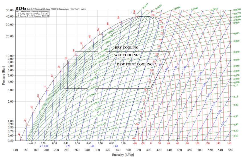
MATEC Web of Conferences 338, 01027 (2021) https://doi.org/10.1051/matecconf/202133801027
PRMR 2021

 Fig. 12. Refrigeration cycle with dew point cooling [9].
 Figure 12 shows how the refrigeration cycle will change its parameters when dew point
 cooling will be applied. It may be concluded that (compares to dry cooling):
 - Condenser capacity (heating capacity) is more than 9% lower,
 - Compressor input is around 41% lower,
 - Mas flow of refrigerant is approximately 14% less,
 - COP – Coefficient of Performance – higher by 67%.
 The presented three evaluations were shown on the lgp-h diagram in Figure 13. It is
 easily visible that the pressure difference between condenser and evaporator can be from ∆p
 = 3.6 bar up to ∆p = 2.5 bar. That gives the possibility to use smaller equipment which will
 consume less energy.
 The present paper provides an overview of evaporative cooling and M-Cycle and its
 applicability in comfort and industry sectors. Maisotsenko cycle combines thermodynamic
 process, heat transfer and evaporative cooling, which is capable to enhance the effectiveness
 of air cooling. This conception is characterized by low energy and water usage. The HVAC
 application of M-Cycle is well known and commercialized but its applicability is still
 undrawn.

 10
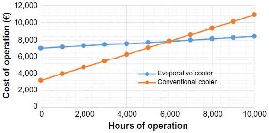
MATEC Web of Conferences 338, 01027 (2021) https://doi.org/10.1051/matecconf/202133801027
PRMR 2021

 Fig. 13. Three different cooling solutions on the lgp-h diagram showing their cooling limits [9].

 7 Conclusions
 Nowadays most HVAC projects for comfort and industry are based on compressor cycle with
 air-cooled condensers. This solution is simple in terms of connections to each modules. Most
 commonly used are chillers which are delivered in a package, as plug and play solution. This
 solution is “on stock” which simplifies installation but not always puts enough effort into
 energy savings. Each installation should be investigated in much more ways than just
 simplification.

 Fig. 14. The operational cost of an evaporative cooler and conventional cooler [12].
 More effectiveness installation, for example with cooling towers, is less likely to use. It
 is mainly by they consume some water which additionally has to be treated and parameters
 kept in constant parameters. Even investment, time and cost, will bring quick savings. This
 was calculated by [12] and it is shown in Figure 14.
 Connection of HMX as air precooling which enters cooling tower should be investigated
 and test in real ambient conditions. Reaching dew point at highest ambient conditions gives

 11
MATEC Web of Conferences 338, 01027 (2021) https://doi.org/10.1051/matecconf/202133801027
PRMR 2021

 additional saving. It could be concluded, by the above shown preliminary investigations, that
 lowering reference temperature from wet-bulb up to dew point has a positive impact on
 energy consumption (directly and indirectly) and also water usage.
 Fact that climate is changing should put more effort into finding and combining the most
 effective solutions like described in this paper IEC with DEC. This paper gives foundations
 for future scientific research. Connection of M-Cycle with the cooling tower will be made.
 Results will be for the polish climate which gives an idea of how much savings (on energy
 and water) we could obtain.

 Nomenclature
 –evaporation temperature,
 –cooling capacity,
 –condensation temperature,
 –heating capacity,
 – compressor input,
 – mass flow of refrigerant,
 C – concentration cycle.
 – evaporation loss
 – cooling capacity of the cooling tower
 Subscrips:
 wb – wet bulb
 db – dry bulb
 c – condenser/condensation
 e – evaporator/evaporation

 12
MATEC Web of Conferences 338, 01027 (2021) https://doi.org/10.1051/matecconf/202133801027
PRMR 2021

 References
 1. Energy Market Agency S.A, Statistics Poland, Enterprises Department, Consumption
 of fuels and energy carriers in 2019, Warsaw (2020)
 2. European Union, Reference Document on the application of Best Available
 Techniques to Industrial Cooling Systems, Ministerstwo Środowiska, Warszawa,
 January (2004)
 3. MITA Cooling Technologies S.r.l.,Via del Benessere, 13, Siziano 27010, Pavia, IT,
 https://www.mitacoolingtechnologies.com/
 4. D. Pandelidis, S. Anisimov, Energy Convers Manag 2015;90:62–83.
 5. S. Anisimov, D. Pandelidis, J. Danielewicz., Energy 2015;80:452–464
 6. S. Anisimov, D. Pandelidis, A. Jedlikowski, V. Polushkin, Energy 2014;76:593–606.
 7. F. Scuderi, M. Proietti, N. De Cardenas, A. Fontana, P. Montrasio, A. Visintini,
 Saving resources by going evaporative: how evaporative cooling technologies and
 water cooled chillers can significantly reduce energy demands, AiCARR, Matera, May
 (2017)
 8. Eurovent 80 Bd. A. Reyers Ln., 1030 Brussels, Belgium, Eurovent Rec 9/13 – 2019,
 December (2019)
 9. CoolPack Version 1,50, IPU & Department of Mechanical Engineering, Technical
 University of Denmark, 2000-2012, https://www.ipu.dk/
 10. Munters Sp. z o.o., Oddział w Polsce, ul. Świętojańska 45/17, 81-391 Gdynia,
 www.munters.com
 11. M. H. Mahmood, M. Sultan, T. Miyazaki, S. Koyama, V. Maisotsenko, Renewable and
 Sustainable Energy Reviews 66 (2016) 537–555, 25 August (2016)
 12. E. D. Rogdakis, D. N. Tertipis, Energy and Emission Control Technologies, Volume
 2015:3 Pages 15—22, 6 March (2015)

 13
You can also read