ABB circuit-breakers for direct current applications
←
→
Page content transcription
If your browser does not render page correctly, please read the page content below
�                    ����������������������������
    September 2007

                                         ABB circuit-breakers
                                         for direct current
                                         applications
    1SDC007104G0201
����������������������������

ABB circuit-breakers for direct current
applications
Index
1 Introduction ....................................... 2                  7 Choice of the protective
                                                                            device .................................................... 20
2 Generalities
  on direct current ........................... 3                         8 Use of alternating current
                                                                            equipment in direct current
3 Applications
                                                                            8.1 Variation of the magnetic field .............. 31
  3.1 Conversion of alternative energies into                               8.2 Connection of the CB poles
            electrical energy ..................................... 5
                                                                                        in parallel .............................................. 33
     3.2    Electric traction ....................................... 7
     3.3    Supply of emergency services or                               9 ABB offer
            auxiliary services ................................... 8
                                                                            9.1 Automatic circuit-breakers ................... 34
     3.4    Particular industrial applications ............ 8
                                                                            9.2 Switch-disconnectors ........................... 41
4 Generation
  4.1 Storage batteries ................................... 9             Annex A:
                                                                          Direct current distribution systems ....................... 42
  4.2 Static conversion .................................. 10
  4.3 Dynamo ............................................... 11           Annex B:
                                                                          Calculation of short-circuit currents ...................... 45
5 Remarks on the interruption                                             Annex C:
  of direct current .......................... 12                         Circuit-breakers and switch-disconnectors for
                                                                          applications up to 1000Vd.c. ................................ 48

6 Typologies of d.c. networks                                             Glossary ................................................................ 52
  6.1 Network insulated from earth .............. 14
  6.2 Network with one polarity earthed........ 16
  6.3 Network with the middle point of the
            supply source connected to earth ....... 18

                                                                                                                                                         1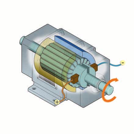
����������������������������

                   1 Introduction
                   Direct current, which was once the main means of                The main purpose is giving precise information by means
                   distributing electric power, is still widespread today in       of tables providing a rapid choice of the protection/dis-
1 Introduction

                   the electrical plants supplying particular industrial ap-       connection device and paying particular attention to the
                   plications.                                                     installation characteristics (fault typologies, installation
                   The advantages in terms of settings, offered by the em-         voltage, earthing arrangement).
                   ploy of d.c. motors and by supply through a single line,
                   make direct current supply a good solution for railway          There are also some annexes giving further information
                   and underground systems, trams, lifts and other trans-          about direct current, and more precisely:
                   port means.                                                     - information about the distribution systems in compli-
                   In addition, direct current is used in conversion plants (in-     ance with the international Standard IEC 60364-1;
                   stallations where different types of energy are converted       - calculation of the short-circuit current in d.c. in compli-
                   into electrical direct energy, e.g. photovoltaic plants)          ance with the international Standard IEC 61660-1;
                   and, above all, in those emergency applications where           - circuit-breakers and disconnectors for applications up
                   an auxiliary energy source is required to supply essential        to 1000Vd.c.
                   services, such as protection systems, emergency lighting,
                   wards and factories, alarm systems, computer centers,
                   etc.. Accumulators - for example – constitute the most
                   reliable energy source for these services, both directly
                   in direct current as well as by means of uninterruptible
                   power supply units (UPS), when loads are supplied in
                   alternating current.
                   This Technical Application Paper is intended to explain to
                   the readers the main aspects of the most impor-
                   tant applications in direct current and to
                   present the solutions offered by
                   ABB SACE products.

                 2 ABB circuit-breakers for direct current applications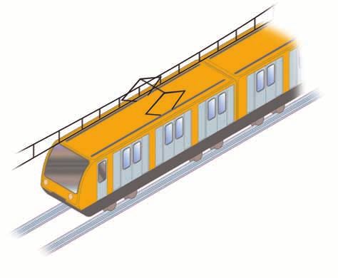
2 Generalities on direct current
Knowing the electrical characteristics of direct current          the current produced by a dynamo can present small
and its differences in comparison with alternating cur-           variations which make it not constant in time; nonethe-

                                                                                                                                    2 Generalities on direct current
rent is fundamental to understand how to employ direct            less, from a practical point of view, this is considered a
current.                                                          direct current.
For definition, the electric current called “direct” has a         Figure 1
unidirectional trend constant in time. As a matter of fact,       Quantity of charge flowing through the cross
                                                                  section of a conductor
by analyzing the motion of the charges at a point crossed
by a direct current, it results that the quantity of charge (Q)
flowing through that point (or better, through that cross
section) in each instant is always the same.
The sources which can provide direct current are batter-
ies or dynamos; besides, through a rectifying process it
is possible to convert an alternating current into a direct
current.
However, a “pure” direct current, that is a current which
does not present any periodic fluctuation, is gener-
                       ated exclusively by batteries (or
                                    accumulators). In fact,

                                                                    In a d.c. system, respecting the current direction has
                                                                      a remarkable importance; therefore it is necessary to
                                                                       connect correctly the loads by respecting the polari-
                                                                        ties, since, in case of a wrong connection, operation
                                                                          and safety problems could arise.

                                                                          For example, if a d.c. motor were supplied by
                                                                          reversing the polarities, it would rotate in the
                                                                          reverse direction and many electronic circuits
                                                                          when supplied in the wrong way could also suffer
                                                                          irreversible damages.

                                                                   ABB circuit-breakers for direct current applications         3
����������������������������

                                     2 Generalities on direct current
                                     R.m.s. value of a sinusoidal quantity                                         current of 100A produces the same thermal effects of a
                                     The r.m.s. value is the parameter which relates alternating                   sinusoidal alternating current with the maximum value
2 Generalities on direct current

                                     to direct current.                                                            of 141A.
                                     The r.m.s. value of an alternating current represents the                     Thus the r.m.s. value allows alternating current to be
                                     direct current value which causes the same thermal ef-                        treated as direct current where the instantaneous value
                                     fects in the same period of time; for example, a direct                       varies in time.

                                                                                                      T
                                                                                                  1
                                                                                                     i ( t ) dt
                                                                                                  T∫
                                                                                                          2
                                                                                      Ir.m.s =                    (where T is the period)
                                                                                                      0

                                     Figure 2 Periodic waveform at 50Hz                                                  Figure 3 R.m.s. value (value of the equivalent direct current)

                                        I (A)                                                                                I (A)

                                                  half period                                                                           Ir.m.s
                                                    10ms                      i (t)

                                                                                                                                I

                                                                                                 t (ms)                                                                             t (ms)

                                                                   period
                                                                   20ms

                                                                            The r.m.s. value of a perfectly sinusoidal waveform is equal to:
                                                              I max
                                                   Ir.m.s=            (where Imax is the maximum value of the amplitude of the sinusoidal waveform)
                                                               2

                                     Figure 4 Sinusoidal waveform at 50Hz                                                Figure 5 R.m.s. value (value of the equivalent direct current)

                                       I (A)                                                                                 I (A)

                                                                                                                                        Ir.m.s
                                                half period
                                                  10ms

                                        Imax
                                                                                                                                 I

                                                                                                 t (ms)                                                                             t (ms)

                                                     period
                                                     20ms

                                   4 ABB circuit-breakers for direct current applications
3 Applications
In the low voltage field, direct current is used for different                  The basic element of a photovoltaic plant is the pho-
applications, which, in the following pages, have been                         tovoltaic cell constituted by semiconducting material

                                                                                                                                                  3 Applications
divided into four macrofamilies including:                                     (amorphous silicon or monocrystalline silicon); this cell,
- conversion into other forms of electrical energy (pho-                       exposed to the rays of the sun, is able to supply a maxi-
  tovoltaic plants, above all where accumulator batteries                      mum current Impp at a maximum voltage Vmpp, which
  are used);                                                                   a maximum power called Wp corresponds to. More
- electric traction (tram-lines, underground railways,                         photovoltaic cells are connected in series to form a string
  etc.);                                                                       to raise the voltage level; by connecting more strings in
- supply of emergency or auxiliary services;                                   parallel, the current level is increased.
- particular industrial installations (electrolytic processes,                 For example, if a single cell can provide 5A at 35.5 Vd.c.,
  etc.).                                                                       in order to reach the level of 100A at 500 Vd.c., it is nec-
                                                                               essary to connect 20 strings in parallel, each of them
                                                                               constituted by 15 cells.

3.1 Conversion of alternative energies into                                    Generally speaking, a stand alone photovoltaic plant is
       electrical energy                                                       constituted by the following devices:
                                                                               - photovoltaic array: constituted by the photovoltaic
Photovoltaic plants                                                              cells suitably interconnected and used for the conver-
A photovoltaic plant permits to convert the energy as-                           sion of sunlight energy into electrical energy;
sociated with solar irradiation into electrical energy of                      - charge regulator: it is an electronic device able to
direct type; these plants are constituted by panels of                           regulate charging and discharging of accumulators;
semiconducting material, which can generate electrical                         - accumulator batteries: they can provide power supply
power once exposed to the rays of the sun.                                       in case of lack of solar radiation;
Photovoltaic plants can be grid-connected or supply a                          - DC/AC inverter: it has the function of turning direct
single load (stand alone plant). In this last case an accu-                      current into alternating current by controlling it and
mulator battery shall be present to provide power supply                         stabilizing its frequency and waveform.
in case of lack of solar radiation.

The following figure shows the block diagram of a stand alone photovoltaic plant..

                                                                                     Photovoltaic array

                  DC/AC
                 converter                         Single module

                                              Charge
                                             regulator
                                                                                                                           String
a.c. load

             d.c. load

                         Battery

                                                                                ABB circuit-breakers for direct current applications          5
����������������������������
The general diagram of a grid-connected photovoltaic current into alternating current by controlling it and
plant, unlike a stand alone one, may leave out the ac- stabilizing its frequency and waveform;
3 Applications
cumulator battery since, when solar irradiation is unavail- - interface device: it is constituted by a circuit-breaker
able, the user is supplied by the network. equipped with an undervoltage release or with a switch-
disconnector able to guarantee the total separation
A photovoltaic plant of this type is constituted by the of the power generation units from the public utility
following equipment: network;
- photovoltaic array: constituted by the photovoltaic - energy meters: they are present to measure and
cells suitably interconnected and used for the conver- invoice the energy supplied and absorbed by the dis-
sion of sunlight energy into electrical energy; tribution network.
- DC/AC inverter: it has the function of turning direct
The following figure shows the block diagram of a grid-connected photovoltaic plant.
Photovoltaic array
Single module
Interface
Meter of device String
the given
Meter of the energy DC/AC
absorbed inverter
energy kWh
kWh
User’s
To the loads
distribution
network
Photovoltaic plants can supply currents from a few doz-
ens of Amperes (domestic applications and similar) up
to several hundreds of Amperes (service industry and
small industry).
6 ABB circuit-breakers for direct current applications3.2 Electric traction It is very important that this power supply is guaranteed
3 Applications
since the auxiliary circuits may supply essential services,
The particular torque-speed characteristic curve and the such as: air conditioning plants, internal and external
ease with which the speed itself can be regulated have led lighting circuits, emergency brake systems, electrical
to the use of d.c. motors in the field of electric traction. heating systems, etc....
Direct current supply gives also the great advantage of The applications of circuit-breakers in d.c. circuits for
having the contact line consisting of a single conductor electric traction in general can be summarized as fol-
since the rails provide the return conductor. lows:
In the present scenario, direct current is used above all - protection and operation of both overhead and rail
in urban transport, that is trolleybuses, trams, under- contact lines;
ground railways with a supply voltage of 600V or 750V, - protection of air compressors on board underground
up to 1000V. and train cars;
The use of direct current is not limited to vehicle traction - protection of distribution plants for services and signal-
only, but direct current represents a supply source for ing systems;
the auxiliary circuits on board vehicles; in such cases - protection of d.c. supply sources (accumulator batter-
accumulator batteries are installed, which constitute an ies)
auxiliary power supply source to be used if the external - protection and operation of d.c. motors.
one should fail.
ABB circuit-breakers for direct current applications 7����������������������������
3.3 Supply of emergency services or 3.4 Particular industrial applications
3 Applications
auxiliary services
The use of direct current is often required in many indus-
Direct current is used (directly or indirectly through ac- trial applications, such as:
cumulator batteries) for all those plants for which service - arc furnaces;
continuity represents a fundamental requirement. - electrowelding plants;
Such plants, which cannot tolerate a power failure - graphite manufacturing plants;
caused, for example, by a loss of energy, need a ready- - metal production and refining plants (aluminum, zinc,
to-use supply source, which, even if limited in time, can etc…).
be however able to cover the times necessary for the In particular, many metals, as aluminum, are produced
starting of an emergency generating set. through an electrolytic process. Electrolysis is a process
Here are some examples of this type of user plants: which converts electric energy into chemical energy. It
- industrial applications (process control systems); is the opposite of what occurs in the battery process. In
- safety and emergency installations (lighting, alarms); fact, with the battery, a chemical reaction is exploited to
- hospital applications; produce d.c. electric energy, whereas electrolysis uses
- telecommunication; d.c. electric energy to start a chemical reaction which
- applications in the data processing field (data centers, otherwise would not occur spontaneously.
work stations, servers, etc…). The procedure consists in immersing the metal to be
refined, which acts as an anode, in a conductive solu-
In these installations, energy interruptions cannot be tion, while a thin plate made of the same pure metal
permitted; therefore, it is necessary to insert in the plant acts as a cathode; by applying a direct current from the
systems able to store energy during the presence of sup- rectifiers, it is possible to observe that the metal atoms
ply and to give it back immediately when energy fails. on the anode dissolve in the electrolytic solution and, at
Accumulator batteries constitute the most reliable elec- the same time, an equivalent quantity of metal settles on
tric energy source for the supply of such services, both the cathode. In these applications, the service currents
directly in direct current (if allowed by the loads) as well are very high >3000A.
as in alternating current by using an inverter able to Another very common application is represented by
develop an outgoing sinusoidal waveform starting from galvanizing plants, where processes are carried out to
an incoming continuous one. obtain the plating of metallic surfaces with other metals
The above is carried out by the uninterruptible power or alloys (chromium plating, nickeling, coppering, brass
supply units (UPS): coating, galvanization zinc plating, tinning, etc....). The
metallic piece to be plated usually acts as a cathode: by
the current flow, the ions shall move from the anode and
Figure 6 Principle diagram of a UPS
shall settle on the piece surface.
Also in these installations, the operations are carried out
by means of an electrolytic cell with high service currents
(up to 3000A and over).
8 ABB circuit-breakers for direct current applications4 Generation
Direct current can be generated: Structure of a storage battery
- by using batteries or accumulators where the current A stationary battery in its easiest form is constituted by a
4 Generation
is generated directly through chemical processes; recipient containing a sulfuric acid solution with distilled
- by the rectification of alternating current through recti- water (the electrolyte) where the two electrodes – the
fiers (static conversion); positive one and the negative one - are immersed. Each
- by the conversion of mechanical work into electrical of them is formed by one or more plates connected in
energy using dynamos (production through rotating parallel; the terminals of these electrodes, to which the
machines). loads shall be connected or where the connections in
series or in parallel shall be made, are the anode (+) and
The following indications are not intended to be an the cathode (-).
exhaustive tool, but they are aimed at giving, in an
The following figure shows the possible structure of three elements
easy language, some useful information to help in the connected in series:
understanding of the main technologies for the produc- connection
between elements
tion of direct current; it is clear that the technology and
anode (+)
techniques used nowadays are manifold and complex,
cathode (–)
but since they are not the main topic of this technical
paper, only the basic indications necessary for a quick
comprehension are given.
single element
with electrolyte
4.1 Storage batteries
A storage battery, or accumulator, is an electrochemical
generator able to convert chemical energy directly into
electrical energy of direct type.
The structure of a storage battery is analogous to that
of a normal battery. The main difference is that with ac- In addition to these components, there are also current
cumulator batteries the discharging/charging process is collectors and separators. The collectors direct the gen-
reversible: in fact, by using a DC generator, it is possible erated current towards the electrodes (discharging phase)
to restore the initial status of the electrodes which have and vice versa from the electrodes towards the elements
been altered during discharge; such process cannot be (charging phase) and the separators, usually constituted
carried out with a normal battery. by insulating plates, avoid the contact between anode
The main electrical characteristics of storage batteries and cathode to prevent the formation of short-circuits.
are: To obtain the voltage level related to the installation re-
- nominal voltage: potential difference existing between quirements, it is necessary to connect (through suitable
the negative and positive plates immersed in the elec- connectors, see figure) more cells in series or in parallel
trolyte; the voltage value usually reported is related to to increase the voltage or the current level.
each single cell (2V, 4V, 6V, 12V); to obtain the required
voltage it is necessary to use more cells in series The following figure shows the possible structure of three elements con-
nected in series:
- capacity: quantity of electricity which a battery can
deliver for a defined time; capacity is expressed in
ampere-hours (Ah) and can be obtained by multiply- –
ing the value of the intensity of the discharge current
(Ampere) by the discharge time (hours)
- internal resistance: the value of the internal resistance
of the battery; this value is given by the manufacturer
- power: power which the battery can deliver; it is ob-
–
tained from the average discharge voltage multiplied +
by the current and it is expressed in watt (W). +
ABB circuit-breakers for direct current applications 9����������������������������
4.2 Static conversion The same occurs in the subsequent fractions of period.
The voltage UR at the terminals of the load R is the voltage
4 Generation
Direct current can be supplied by using electronic de- represented by the envelope of the line-to-line voltages
vices (rectifiers) able to convert alternating current input as shown in the figure.
into direct current output. Such devices are also called
static converters to distinguish them from the rotating V U12 U13=-U31 U23 U21=-U12 U31 U32=-U23
ones, nowadays obsolete equipment, which use more Umax
Umed
electrical machines suitably coupled. The operating
principle of rectifiers exploits the properties of the elec-
tronic components made of semiconductor materials
(diodes, thyristors, etc.), that is their capacity of carrying
currents only when positively polarized. The operating
principle can be described by taking into consideration
the three-phase bridge rectifier (Graetz rectifier) shown 0
t1 t2 t3 t4 t5 t6
in the figure: t
I
1 3 5
UR
R
The continuous lines represent the three sine curves of the line-to-line voltages
(U12 ; U23 ; U31), whereas the dotted lines represent the sine curves of the same
voltages but reversed (U13 = -U31 ; U21 = -U12 ; U32 = -U23).
U1 U2 U3
The resulting output voltage (represented by the conti-
2 4 6
nuous black line) takes the waveform of a ripple voltage
with average value not null.
Therefore, the direct current which flows through the
In this diagram it is possible to identify the three forward diodes (1,3,5) having resistance R shall be equal to:
the cathodes connected in common and the three backward diodes (2,4,6)
which instead have the anodes connected in common. Umed
I=
R
Having established that a diode carries current only if
positively polarized, that is when the voltage at its ends In fact the electronic circuit of a rectifier is more complex
is higher than zero, by supplying the bridge circuit with than the circuit just shown; for example, a capacitor
a set of three-phase voltages, it results: which “smoothes” the output voltage is often present
to reduce ripple. Besides, thyristors can be used in-
a) during the first sixth of period, the line-to-line voltage stead of diodes; thyristors, thanks to the possibility of
U12 is the prevailing voltage; as a consequence diodes controlling their switching-on time in relation with their
1 and 4 shall carry the current switching instant, allow to vary the output voltage value
b) during the second sixth of period, the line-to-line vol- at the bridge; in this case, this device is referred to as a
tage U13 is the prevailing voltage; as a consequence, controlled bridge rectifier.
diodes 1 and 6 shall carry the current.
10 ABB circuit-breakers for direct current applications4.3 Dynamo Starting from the assumption that a straight-line con-
ductor (positioned along a cylinder rotating at constant
4 Generation
A dynamo is a direct current generator used to convert speed) cutting the lines of force of the magnetic field
kinetic energy into electrical energy of direct type. becomes the seat of an induced electromotive force
As shown in the figure, these devices consist chiefly of (emf) variable in time, it is easy to understand that with
a stationary structure (called inductor system), having more conductors suitably connected (so that the positive
the task of generating a magnetic field, and of a moving and negative values of the electromotive forces induced
part (called rotor), constituted by a system of conductors, in the conductors are compensated), it is possible to
which shall be “struck” by the magnetic field generated obtain a resulting emf of constant value having always
by the inductor. the same direction.
The following figure shows the structure of a dynamo:
Stationary structure (inductor system)
Moving part (rotor)
ABB circuit-breakers for direct current applications 11����������������������������
5 Remarks on the interruption of direct current
Direct current presents different problems than alternat- To understand the above, reference to the circuit shown
ing current with aregard to the phenomena associated in the figure shall be made:
5 Remarks on the interruption of direct current
to the interruption of high value currents since the arc
extinction results to be particularly difficult. L R
As Figure 7 shows, with alternating current there is natu- L
di
iR
ral passage of current through zero at each half cycle, dt
which corresponds to the quenching of the arc during
the circuit opening. With direct current there is not such
natural passage and therefore, to guarantee arc extinc- Ua
tion, the current must decrease to null (forcing the current
passage through zero). U
Figure 7 Alternating current
I (A)
current passage through 0
half cycle In this case:
10ms
di
U=L + Ri + Ua
dt
where:
t (ms) U is the rated voltage of the supply source
L is the inductance of the circuit
cycle R is the resistance of the circuit
20ms
Ua is the arc voltage.
The formula can be written also as:
di
L = U - Ri - Ua (1)
Figure 8 Direct current dt
To guarantee arc extinction, it is necessary that:
I (A)
diThe following figure shows an oscillogram relative to a resistance progressively introduced in the circuit. As it
short-circuit test carried out in ABB SACE power testing can be noticed in the graph, the arc voltage keeps higher
5 Remarks on the interruption of direct current
laboratories. than the supply voltage of the circuit during the interrup-
tion. In correspondence of ta, the current is completely
T quenched.
I/U
As the graph shows, the short-circuit current represented
by the red line is extinguished without abrupt interrup-
Icn
tions which could cause high voltage peaks.
Ip Ua
As a consequence, to obtain a gradual extinction (the
graph represents the descent of Ip), it is necessary to
cool and extend the arc, so that a higher and higher arc
Un resistance is inserted in the circuit (with the consequent
increase of the arc voltage Ua). This extinction involves
energetic phenomena which depend on the voltage level
of the plant (Un) and lead to install circuit-breakers ac-
0 cording to connection diagrams in series to the advan-
t
to ts ta tage of the performances under short-circuit conditions
(as a matter of fact, the higher is the number of contacts
Ip = short-circuit making current opening the circuit, the higher is the breaking capacity
Icn = prospective short-circuit current of the circuit-breaker).
Ua = maximum arc voltage
Un = network voltage This means that, when the voltage rises, it is neces-
T = time constant sary to increase the number of current interruptions in
to = instant of beginning of short-circuit series, so that a rise in the arc voltage is obtained and
ts = instant of beginning of separation of the CB con consequently a number of poles for breaking operation
tacts suitable to the fault level.
ta = instant of quenching of the fault current As regards the pole connection referred to network
typologies, see Chapter 7: “Choice of the protective
device”.
When a short-circuit occurs, in correspondence to the
instant to, the current starts rising according to the time To summarize: in order to guarantee breaking of a short-
constant of the circuit. The circuit-breaker contacts circuit current in a d.c. system it is necessary to employ
begin separating, thus striking an arc starting from the circuit-breakers which can ensure:
instant ts. - rapid tripping with adequate breaking capacity;
- high fault current limiting capacity;
The current keeps on rising for a short instant also after - overvoltage reduction effect.
the beginning of contact opening, and then decreases
depending on the value higher and higher of the arc
ABB circuit-breakers for direct current applications 13����������������������������
6 Typologies of d.c. networks
As previously explained, in order to break a short-circuit 6.1 Network insulated from earth
current in a d.c. system, it is necessary to connect the
6 Typologies of d.c. networks
CB poles in a suitable way. This type of network represents the easiest connection
To carry out this operation, it is necessary to know the to carry out, since no connection between the battery
earthing typology of the plant. polarities and earth are provided.
Such information allow any possible fault condition to be
evaluated and consequently the most suitable connection These types of systems are widely used in those instal-
type to be selected according to the other characteristics lations where earthing results to be difficult, but above
of the plant (short-circuit current, supply voltage, rated all where service continuity is required after a first earth
current of the loads, etc.). fault (see the following pages).
The following pages shall give for each network typology
these fundamental information: On the other hand, since no polarities are earthed, this
- description of the network connection presents the inconvenience that dangerous
- fault typologies. overvoltages could occur between an exposed conduc-
(as regards the pole connection and the relevant break- tive part and earth due to static electricity (such hazards
ing capacity see Chapter 7: ”Choice of the protective can be limited by overload dischargers).
device”)
Common solution Representation in compliance with Std. IEC 60364-1*
Figure 9 Network insulated from earth
Figure 10 IT d.c. distribution systems
L+
U R
L-
Exposed conductive parts
Earthing of exposed
conductive parts
*such analogy is valid for the earthing of the supply source only and not for the earthing
of the exposed-conductive-parts; besides, as far as the prescriptions concerning indirect
contacts are concerned, please refer to Std. IEC 60364-4.
14 ABB circuit-breakers for direct current applicationsFault typologies in a network insulated
from earth
6 Typologies of d.c. networks
Double fault (fault B + fault C):
Fault A: in case of a double fault, as shown in the figure, the cur-
the fault between the two polarities is a short-circuit rent might circulate and find a reclosing path; in this case,
current fed by the full voltage U. The breaking capacity it is advisable that a device capable of signaling an earth
of the circuit-breaker shall be chosen according to the fault or a decrease of the insulation to earth of a polarity is
short-circuit current relevant to such fault. installed in the plant; thus, the fault is eliminated in good
time to prevent the occurrence of a second earth fault on
the other polarity and the consequent total inefficiency
+ Ik
of the plant due to the tripping of the CB caused by the
U Fault A R short-circuit generated on the two polarities to earth.
–
+ Ik
U Fault B R
Fault B: –
the fault between a polarity and earth has no consequen-
ces from the point of view of the plant operation since
such current has no reclosing paths and consequently Fault C
it cannot circulate.
+ Conclusion:
With this typology of network, the fault type which af-
Fault B R
fects the version and connection of the CB poles is fault
– A (between the two polarities).
In an insulated network it is necessary to install a device
able to signal the presence of the first earth fault so that
no reclosing path it can be eliminated to avoid any problem arising from
a second earth fault. In fact, in case of a second earth
fault, the CB could have to interrupt the fault current,
under the worst conditions, with the full voltage applied
Fault C: to a single polarity and consequently with an insufficient
also this fault (as fault B) between a polarity and earth arc voltage (see figure).
has no consequences from the point of view of the plant
operation. Figure 11 Double fault in a network insulated from earth
+
+
load
R
U
–
–
no reclosing path Fault C
ABB circuit-breakers for direct current applications 15����������������������������
6.2 Network with one polarity earthed This connection type allows the overvoltages due to static
6 Typologies of d.c. networks
electricity to be discharged to earth.
This typology of network is obtained by connecting to
earth one polarity (either the negative or the positive
one).
Representation in compliance with Std. IEC 60364-1*
Figure 13 TT d.c. distribution system
L+
L-
Common solution
Figure 12 Network with one polarity earthed
+ Exposed conductive parts
Earthing of system Earthing of exposed
U R conductive parts
– Figure 14 TN C-S d.c. distribution system
L+
PEN (d.c.)
PE
L-
Exposed conductive parts
Earthing of system
TN-C system TN-S system
TN-C-S d.c. system
*such analogy is valid for the earthing of the supply source only and not for the earthing
of the exposed-conductive-parts; besides, as far as the prescriptions concerning indirect
contacts are concerned, please refer to Std. IEC 60364-4.
16 ABB circuit-breakers for direct current applicationsFault typologies in a network with one polarity earthed
6 Typologies of d.c. networks
(in the following examples the earthed polarity is the negative one)
Fault A: Fault C:
the fault between the two polarities is a short-circuit The fault on the earthed polarity sets up a current which
current fed by the full voltage U. The breaking capacity affects the overcurrent protections as a function of the
of the circuit-breaker shall be chosen according to the soil resistance; such current presents an extremely low
short-circuit current relevant to such fault. value because it depends on the impedance of the soil
and the U is next to zero (since the voltage drop on the
+ Ik load further reduces its value).
U Fault A R
– + Ik
R
U
–
Fault C
Fault B:
the fault on the non-earthed polarity sets up a current
involving the overcurrent protections as a function of the Conclusions
soil resistance. With this typology of network, the fault type which affects
the version of the CB and the connection of the poles is
+
fault A (between the two polarities), but it is necessary to
Ik
take into consideration also the fault between the non-
Fault B R earthed polarity and the earth itself (fault B) since, as
U described above, a current (with the value depending also
–
by the impedance of the soil and consequently difficult to
assess) could flow at full voltage; for this reason, all the
CB poles necessary for protection shall be connected in
series on the non-earthed polarity.
ABB circuit-breakers for direct current applications 17����������������������������
6.3 Network with the middle point of the voltages, which otherwise could be present at full voltage
6 Typologies of d.c. networks
supply source connected to earth in an insulated plant.
The main disadvantage of this connection, if compared
This typology of network is obtained by connecting the with other types, is that a fault between a polarity, both
middle point of the battery to earth. a negative as well a positive one, and earth gives rise to
This type of connection reduces the value of static over- a fault current at a voltage U .
2
Representation in compliance with Std. IEC 60364-1*
Figure 16 TT d.c. distribution system
L+
Common solution M
L-
Figure 15 Network with the middle point connected to earth
Esposed conductive parts
U R Earting of exposed
Earthing of system
conductive parts
Figure 17 TN-C-S d.c. distribution system
L+
PEN (d.c.)
PE
L-
M
Exposed conductive parts
Earthing of system
TN-C system TN-S system
TN-C-S d.c. system
*such analogy is valid for the earthing of the supply source only and not for the earthing
of the exposed-conductive-parts; besides, as far as the prescriptions concerning indirect
contacts are concerned, please refer to Std. IEC 60364-4.
18 ABB circuit-breakers for direct current applicationsFault typologies in a network with the middle point connected to earth
6 Typologies of d.c. networks
Fault A: Fault C:
the fault between the two polarities is a short-circuit In this case, the fault is analogous to the previous case,
current fed by the full voltage U. The breaking capacity but it concerns the negative polarity.
of the circuit-breaker shall be chosen according to the
short-circuit current relevant to such fault.
+ Ik +
U Fault A R R
– –
Ik
U
2 Fault C
Fault B: Conclusion
The fault between the polarity and earth sets up a short- With this typology of network the fault which affects the
circuit current lower than that relevant to the fault be- version of the CB and the connection of the poles is fault
tween the two polarities, since it is supplied by a voltage A (between the two polarities); however, also the fault
equal to U depending on the soil resistance. between a polarity and earth (with reference to the above
2
diagrams) should be taken into consideration because,
as previously described, a current (the value of which
+ Ik
depends also on the impedance of the soil) could flow
Fault B R U .
at a voltage equal to
U 2
– 2 In a network with the middle point of the supply con-
nected to earth, the circuit-breaker must be inserted
necessarily on both the polarities.
ABB circuit-breakers for direct current applications 19����������������������������
7 Choice of the protective device
For the correct dimensioning of a circuit-breaker in a Rated service short-circuit breaking capacity Ics
direct current network, some electrical parameters which The rated service short-circuit breaking capacity of a
7 Choice of the protective device
characterize the device itself must be evaluated. circuit-breaker is the maximum short-circuit current
Here is a short description of these parameters, which value which the circuit-breaker can break three times
are mentioned in the following pages. in accordance with a sequence of opening and closing
operations (O - t - CO - t – CO) at a defined rated opera-
Rated operational voltage Ue tional voltage (Ue) and at a defined time constant (for
It represents the value of voltage which determines the direct current). After this sequence the circuit-breaker is
application of the equipment and to which all the other required to carry its rated current.
parameters typical of the equipment are referred.
Rated short-time withstand current Icw
Rated uninterrupted current Iu The rated short-time withstand current is the current that
It represents the value of current which the equipment can the circuit-breaker in the closed position can carry dur-
carry for a indefinite time (uninterrupted duty). This pa- ing a specified short time under prescribed conditions
rameter is used to define the size of the circuit-breaker. of use and behaviour; the circuit-breaker shall be able to
carry this current during the associated short-time delay
Rated current In in order to ensure discrimination between the circuit-
It represents the value of current which characterizes breakers in series.
the protection trip unit mounted on the circuit-breaker
and determines the protection characteristic of the cir-
cuit-breaker itself according to the available settings of
the trip unit.
This current is often referred to the rated current of the
load protected by the circuit-breaker itself.
Rated ultimate short-circuit breaking capacity Icu
The rated ultimate short-circuit breaking capacity of a
circuit-breaker is the maximum short-circuit current value
which the circuit-breaker can break twice (in accordance
with the sequence O – t – CO) at the corresponding
rated operational voltage. After the opening and closing
sequence the circuit-breaker is not required to carry its
rated current.
20 ABB circuit-breakers for direct current applicationsRating plates of the circuit-breakers
Tmax molded-case circuit-breakers for direct current
7 Choice of the protective device
CIRCUIT-BREAKER TYPE
Series Size
Size Rated ultimate short-circuit Rated
T breaking capacity at 250 Vd.c. uninterrupted
11 (with 2 poles in series)
22 current
N = 36 kA 160 A
33 S = 50 kA
44 250 A
H = 70 kA
55 320 A
L = 85 kA (for T2)
66 L = 100 kA 400 A
V = 150 kA 630 A
7
800 A
Rated uninterrupted
current
Rated insulation voltage
Rated operational
voltage
Rated impulse
withstand voltage
Compliance with the International
Tmax T2L160 Iu=160A Ue=690V Ui=800V Uimp=8kV IEC 60947-2 Standard IEC60947-2:
“Low-voltage switchgear and
Ue (V) 230 400/415 440 500 690 250 500 Made in Italy controlgear - Circuit-Breakers”
Icu (kA) 150 85 75 50 10 85 85 by ABB SACE
Ics (% Icu) 75 75 75 75 75 75 75
Cat A 50-60Hz 2P 3P
in series
Part relevant to direct current
according to the number of poles connected
in series called to extinguish the fault current
the rated operational voltage and the breaking
capacities (Icu and Ics) are indicated
According to the international Standard IEC 60947-2, CE marking affixed on ABB circuit-
the circuit-breakers can be divided into: breakers to indicate compliance with the
- category A, i.e. circuit-breakers without a specified following CE directives:
short-time withstand current rating; -“Low Voltage Directive” (2006/95/EC)
- category B, i.e. circuit-breakers with a specified -“Electromagnetic Compatibility Directive
short-time withstand current rating (2004/108/EC)
Rated ultimate short-circuit breaking
capacity (Icu) and rated service
short-circuit breaking capacity (Ics)
ABB circuit-breakers for direct current applications 21����������������������������
Emax air circuit-breakers for direct current
7 Choice of the protective device
CIRCUIT-BREAKER TYPE
Series Size Rated ultimate short-circuit Rated
E 2 breaking capacity at 500 Vd.c. uninterrupted
3 current
4 B = 35 kA (E2) 800 A
6 N = 50 kA (E2) 1000 A
N = 60 kA (E3) 1250 A
S = 75 kA (E4) 1600 A
H = 85 kA (E3) 2000 A
H = 100 kA (E4-E6) 2500 A
3200 A
4000 A
5000 A
Rated ultimate short-circuit breaking
capacity (Icu) and rated service
short-circuit breaking capacity (Ics)
Rated uninterrupted
current
Rated short-time withstand
current (Icw)
Rated operational
voltage (Ue) International Standard IEC60947-2:
“Low voltage switchgear and
controlgear - Circuit-breakers”
SACE E2B 800 Iu=800A Ue=1000V Icw=35kA x 0.5s
Ue (V) 500 750 1000 IEC 60947-2
+ - made in Italy by
Icu (kA) 35 25 25 ABB-SACE
Ics (kA) 35 25 25
+ -
Cat B 4P
Connection modality to the circuit-breaker poles:
the connection in series shown in the scheme
is carried out in the factory by ABB SACE
According to the international CE marking affixed on ABB circuit-
Standard IEC 60947-2, the circuit- breakers to indicate compliance with the
breakers can be divided into: following CE directives:
- category A, i.e. circuit-breakers -“Low Voltage Directive” (2006/95/EC)
without a specified short-time -“Electromagnetic Compatibility Directive
withstand current rating; (2004/108/EC)
- category B, i.e. circuit-breakers
with a specified short-time
withstand current rating.
22 ABB circuit-breakers for direct current applicationsDimensioning of circuit-breakers the relation Ik ≤ Icu (at the reference rated operational
7 Choice of the protective device
In the previous pages the main electrical characteristics voltages Ue);
of a circuit-breaker have been defined, which are neces- - the rated current absorbed by the load (Ib) to define
sary for a correct choice of the circuit-breaker so that the rated current (In) of the thermal-magnetic trip unit
protection of the plant is guaranteed. or of the new d.c. electronic release (PR122-PR123/DC
To proceed with the dimensioning it is necessary to know for Emax) by verifying the relation Ib≤ In.
the following characteristics of the network:
- the type of network (see Chapter 6) to define the con- Procedures to guarantee the correct dimensioning
nection of the circuit-breaker poles according to the of a circuit-breaker:
possible fault conditions; The following diagram summarizes schematically the
- the rated voltage of a plant (Un) to define the opera- choices to be carried out for a correct dimensioning of
tional voltage (Ue) depending on the pole connection the circuit-breaker in relation to the characteristics of
by verifying the relation: Un≤ Ue; the plant.
- the short-circuit current at the installation point of the
circuit-breaker (Ik) to define the circuit-breaker version
(depending on the connection of the poles) by verifying
Typology of connection earthing
Ue ≥ Un
Icu (according to the number of poles in series) ≥ Ik
In ≥ Ib
ABB circuit-breakers for direct current applications 23����������������������������
The values given in the following tables indicate the performances of circuit-breakers under the heaviest fault condi-
tions which characterize the typology of network under consideration (see Chapter 6: “Typologies of d.c. networks”);
7 Choice of the protective device
the prescribed connections shall be carried out by the customer.
As regards the electrical characteristics of the mentioned circuit-breakers see Chapter 9 “ABB offer”.
Table1-2 Connection modality of poles (for MCBs type S280 UC-S800S UC) in an insulated network
INSULATED NETWORK INSULATED NETWORK
Rated voltage (Un) ≤ 500 ≤ 750 Rated voltage (Un) ≤ 440
+ - + - + -
Protection 1 3 1 3 5 7 Protection 1 3 5 7
+ 2 4 2 4 6 8 + 2 4 6 8
isolation function isolation function
S800S UC In = 10…125 A 50 50 In = 0,5…2 A 50
S280 UC In = 3…40 A 6
In = 50…63 A 4,5
Table 3-4 Connection modality of poles (for MCBs type S280 UC-S800S UC) in a network with one polarity earthed
NETWORK WITH ONE POLARITY EARTHED
Rated voltage (Un) ≤ 250 ≤ 500 ≤ 750
+ - + - + -
1 1 3 1 3 5
Protection function 2 2 4 2 4 6
S800S UC In = 10…125 A 50 50 50
NETWORK WITH ONE POLARITY EARTHED
Rated voltage (Un) ≤ 220 ≤ 440
+ - + -
1 1 3
Protection function 2 2 4
+ -
Protection 1 3
+ 2 4
isolation function
In = 0,5…2 A 50 50 50
S280 UC In = 3…40 A 6 10 6
In = 50…63 A 4,5 6 4,5
Table 5 Connection modality of poles (for MCBs type S280 UC) in a network with the middle point earthed
NETWORK WITH THE MIDDLE POINT CONNECTED TO EARTH
Rated
≤ 220
voltage (Un)
+ -
Protection 1 3
+ 2 4
isolation function
+ -
In = 0,5…2 A 50
S280 UC In = 3…40 A 10
In = 50…63 A 6
24 ABB circuit-breakers for direct current applicationsTable 6 Connection modality of poles (for MCCBs type Tmax) in an insulated network*
7 Choice of the protective device
INSULATED NETWORK
Rated voltage
≤ 250 ≤ 500 ≤ 750
(Un)
+ - + - + - + - + -
Protection
+
isolation function
LOAD LOAD LOAD LOAD LOAD
B 16 20 16
T1
C 25 30 25
160
N 36 40 36
N 36 40 36
T2 S 50 55 50
160 H 70 85 70
L 85 100 85
T3 N 36 40 36
250 S 50 55 50
N 36 25 16
T4
250/320 S 50 36 25
H 70 50 36
T5 L 100 70 50
400/630
V 150 100 70
N 36 20 16
T6 S 50 35 20
630/800 H 70 50 36
L 100 65 50
The positive pole (+) can be inverted with the negative pole (-).
* with these typologies of pole connection the possibility of a double fault to earth is considered unlikely (see Chapter 6: “Typologies of d.c. networks”)
ABB circuit-breakers for direct current applications 25����������������������������
Table 7 Connection modality of poles (for MCCBs type Tmax) in a network with one polarity earthed (in the considered connections, the earthed
polarity is the negative one)
7 Choice of the protective device
NETWORK WITH ONE POLARITY EARTHED
Rated
≤ 250 ≤ 500 ≤ 750
voltage (Un)
+ - + - + -
+ - + -
Protection
+
isolation function
LOAD LOAD LOAD LOAD LOAD
+ - + - + - + - + -
Protection
function
LOAD LOAD LOAD LOAD LOAD
B 16 20 16
T1
C 25 30 25
160
N 36 40 36
N 36 40 36
T2 S 50 55 50
160 H 70 85 70
L 85 100 85
T3 N 36 40 36
250 S 50 55 50
N 36 25 16
T4
250/320 S 50 36 25
H 70 50 36
T5 L 100 70 50
400/630
V 150 100 70
N 36 20 16
T6 S 50 35 20
630/800 H 70 50 36
L 100 65 50
26 ABB circuit-breakers for direct current applicationsTable 8 Connection modality of poles (for MCCBs type Tmax) in a network with the middle point earthed
7 Choice of the protective device
NETWORK WITH THE MIDDLE POINT CONNECTED TO EARTH
Rated
≤ 250* ≤ 500** ≤ 750
voltage (Un)
+ - + - + -
Protection
+
isolation function
LOAD LOAD LOAD
B 20 16
T1
C 30 25
160
N 40 36
N 40 36
T2 S 55 50
160 H 85 70
L 100 85
T3 N 40 36
250 S 55 50
N 36 25 16
T4 S 50 36 25
250/320
H 70 50 36
T5
400/630 L 100 70 50
V 100 100 70
N 36 20 16
T6 S 50 35 20
630/800 H 70 50 36
L 100 65 50
* for the use of three-phase circuit-breakers please ask ABB
** for the use of three-phase circuit-breakers (T4-T5-T6) please ask ABB
ABB circuit-breakers for direct current applications 27����������������������������
The values given in the following tables indicate the performances of circuit-breakers under the heaviest fault con-
ditions which characterize the typology of network under consideration (see Chapter 6: “Typologies of networks”);
7 Choice of the protective device
the connections prescribed in the table (carried out in the factory by ABB SACE) refer to Emax air circuit-breakers
equipped with the new d.c. electronic trip unit type PR122/PR123 DC.
As regards the electrical characteristics of the mentioned circuit-breakers see Chapter 9 “ABB offer”.
Tables 9-10 Connection modality of poles for (ACBs type Emax) in an insulated network and with one polarity earthed (in the considered connections, the
earthed polarity is the negative one)
INSULATED NETWORK* NETWORK WITH ONE POLARITY EARTHED
Rated Rated
voltage ≤ 500 ≤ 750 ≤ 1000 voltage < 500**
(Un) (Un)
3-pole circuit-breaker 3-pole circuit-breaker 4-pole circuit-breaker 3-pole circuit-breaker
+ - + - + LOAD - + -
LOAD LOAD LOAD
Protection Protection
+ +
isolation isolation
function function
LOAD LOAD LOAD
B 35 25 25 B 35
E2 E2
N 50 35 35 N 50
N 60 50 35 N 60
E3 E3
H 85 65 65 H 85
S 75 65 50 S 75
E4 E4
H 100 85 65 H 100
E6 H 100 85 65 E6 H 100
* with these typologies of pole connection the possibility of a double fault to earth is considered unlikely (see Chapter 6: “Typologies of d.c. networks”)
** for higher voltages please ask ABB
Table 11 Connection modality of poles for (ACBs type Emax) in a network with the middle point earthed
NETWORK WITH THE MIDDLE POINT CONNECTED TO EARTH
Rated
voltage < 500 < 750 ≤ 1000
(Un)
3-pole circuit-breaker 4-pole circuit-breaker 4-pole circuit-breaker
+ - + LOAD - + LOAD -
LOAD
Protection
+
isolation
function
LOAD
B 35 25 25
E2
N 50 35 35
N 60 50 35
E3
H 85 65 65
S 75 65 50
E4
H 100 85 65
E6 H 100 85 65
28 ABB circuit-breakers for direct current applicationsThe following tables show the pole connections of Tmax switch-disconnectors according to the installation voltage;
the connections shown in the table shall be carried out by the customer.
7 Choice of the protective device
Table 12 Connection modality of poles for Tmax switch-disconnectors
Rated
≤ 250 ≤ 500 ≤ 750
voltage (Un)
+ - + - + - + -
Pole connection
LOAD LOAD LOAD LOAD
T1D 160 ■ - ■ -
T3D 250 ■ - ■ -
T4D 250/320 ■ ■ - ■
T5D 400/630 ■ ■ - ■
T6D 630/800/1000 ■ ■ - ■
T7D 1000/1250/1600 ■ ■ ■ ■
Table 13 Connection modality of poles for Emax switch-disconnectors
Rated
≤ 500 ≤ 750 ≤ 1000
voltage (Un)
+ - + - + - + LOAD -
LOAD
Pole connection
LOAD
LOAD LOAD
X1-E1…E6 / MS ■ - - -
E1…E6 E/ MS ■ ■ ■ ■
ABB circuit-breakers for direct current applications 29����������������������������
Choice of a molded-case circuit-breaker Choice of a an air circuit-breaker type Emax
type Tmax Example
7 Choice of the protective device
Example Characteristics of the plant:
Characteristics of the plant: • Type of network: insulated
• Type of network: one polarity earthed (the negative • Network voltage: Un = 500Vd.c.
one) • Rated voltage absorbed by the loads (Ib): 1800A
• Network voltage: Un = 250Vd.c. • Short-circuit current: 45kA
• Rated voltage absorbed by the loads (Ib): 450A
• Short-circuit current: 40kA
Choice of the circuit-breaker
Choice of the circuit-breaker Making reference to the indications given on page 23, to
Making reference to the indications given on page 23, to proceed with a correct dimensioning of the circuit-breaker
proceed with a correct dimensioning of the circuit-breaker the following prescriptions must be complied with:
the following prescriptions must be complied with: • Ue ≥ Un
• Ue ≥ Un • Icu ≥ Ik
• Icu ≥ Ik • In ≥ Ib
• In ≥ Ib
With reference to the type of network, the suitable table
With reference to the type of network, the suitable table shall be identified among the tables 9-10-11; in this case
shall be identified among the tables 6-7-8; in this case the table relevant to an insulated network (Table 9) shall
the table relevant to a network with one polarity earthed be chosen.
(Table 7) shall be chosen. The column with the performances referred to a network
The column with the performances referred to a network voltage higher than or equal to the plant voltage shall be
voltage higher than or equal to the plant voltage shall be identified, in this example Un≥ 500Vdc.
identified, in this example Un≥ 250Vd.c. From the column considered, the circuit-breaker which
The load current is the reference necessary to identify would seem suitable for its performances under short-
the row of the table referred to the circuit-breakers with circuit conditions is the CB type E2N (N=50kA>Ik), but
uninterrupted rated current Iu higher than or equal to the according to the table relevant to the rated uninterrupted
load current; in the case considered as example a circuit- current (page 39) it is necessary to pass to a CB type
breaker type Tmax T5 with Iu=630A can be used. E3N since it has Iu= 2000A (this value corresponds to
The version (N –S – H etc.) is chosen according to the the In of the trip unit), value higher than the current ab-
relation Icu≥Ik. In this example, since Ik=40kA, version sorbed by the loads; in this way, the third relationship is
S can be used. complied with.
With these bonds limiting the choice, two possible Therefore the suitable circuit-breaker is a three-pole
schemes for the pole connection can be identified and circuit-breaker type E3N 2000 with PR1122-123/DC
assuming that also the earthed polarity is to be discon- In=2000 A (the connection of the poles is carried out in
nected the connection scheme to be used is the fol- the factory by ABB SACE).
lowing: The solution of the table shows the connections between
+ -
three-pole circuit-breaker, load and supply source.
+ -
LOAD
LOAD
Among the rated currents available for the thermomag- LOAD
netic trip units of the circuit-breaker T5S630, that with
In=500A shall be chosen; therefore, to summarize, a
three-pole thermomagnetic circuit-breaker T5S630 TMA
500 shall be used connected as shown in the figure,
i.e. with two poles in series on the polarity insulated
from earth and the other one connected on the earthed
polarity.
30 ABB circuit-breakers for direct current applications8 Use of alternating current equipment in
direct current
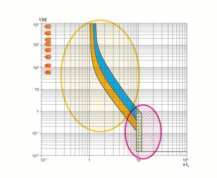
8.1 Variation of the magnetic tripping cuit, due to ferromagnetic phenomena, the instantaneous
tripping occurs at a different value in comparison with the
8 Use of alternating current equipment in direct current
The thermal magnetic trip units fitted to a.c. circuit-break- analogous case in alternating current (the green area in
ers are also suitable to be used with direct current. the figure shows the shifting of the magnetic tripping). A
The part relevant to the thermal protection does not coefficient, called km, variable as a function of the circuit-
change with reference to its tripping characteristic since breaker and of the connection type of its poles, allows to
the bimetal strips of the trip units are influenced by the derive the d.c. instantaneous trip threshold starting from
heating caused by the current flow, it does not matter the relevant value in alternating current; therefore, this
whether alternating or direct: in fact the bimetal strips coefficient is to be applied to the threshold I3.
are sensitive to the r.m.s. value.
As regards the instantaneous protection against short-cir-
No variation in the
tripping due to
overload
Variation in the
instantaneous
tripping due to
short-circuit
ABB circuit-breakers for direct current applications 31����������������������������
On the contrary, there is no derating for Emax series to the circuit-breaker type and to the connection modality
circuit-breakers equipped with the new d.c. electronic of the poles (the given diagrams are valid for all typolo-
8 Use of alternating current equipment in direct current
releases type PR122-PR123/DC because the trip times gies of networks because the coefficient km depends
comply with the curve set on the electronic trip unit. exclusively on the circuit-breakers characteristics).
The following table reports the coefficient km according
Table 14 Coefficient km according to the connection modality of the CB poles
Connection Circuit-breaker
modality T1 T2 T3 T4 T5 T6
+ -
1.3 1.3 1.3 1.3 1.1 1.1
LOAD
+ -
1 1.15 1.15 1.15 1 1
LOAD
+ -
1 1.15 1.15 1.15 1 1
LOAD
+ - Example
With a circuit-breaker type T2N 160 TMD In=160 (having
- - - 1 0.9 0.9 the a.c. magnetic tripping I3=10xIn) and choosing a pole
LOAD connection corresponding to the first figure of Table 14,
it is possible to visualize the coefficient km equal to 1.3;
+ - the d.c. magnetic tripping shall be equal to:
- - - 1 0.9 0.9 I3 = 10 x In x km = 10 x 160 x 1.3 = 2080 A
LOAD
(±20% tolerance)
+ -
- - - 1 0.9 0.9
LOAD
+ -
- - - - - 1
LOAD
+ -
- - - - - 0.9
LOAD
32 ABB circuit-breakers for direct current applications8.2 Connection of the CB poles in parallel For example, by using a circuit-breaker type T6N 800
8 Use of alternating current equipment in direct current
and connecting two poles in parallel for each polarity,
Molded-case circuit-breakers of series Tmax equipped the rated uninterrupted current shall be equal to:
with thermal magnetic trip units can be used both for
alternating current as well as for direct current; when used In = In x n° no.of poles in parallel x K = 800 x 2 x 0.9 = 1440 A
for d.c. applications, they are available for rated current
from 1.6A (T2 CBs) up to 800A (T6 CBs). However, it is necessary to take into consideration the
For applications where higher currents are required, it is likely fault typologies in relation to the earthing arrange-
possible to connect the CB poles in parallel, so that the ment of the plant.
required current carrying capacity can be obtained. ABB SACE advises against the connection in parallel,
When choosing a circuit-breaker, it is necessary to con- since it results quite difficult to realize a connection which
sider the fact that the connection of the poles in parallel can guarantee that the currents flowing in the CB poles
involves, in addition to the variation of the magnetic trip- are perfectly balanced. Therefore, for rated operational
ping, also a derating to be applied to the rated current of currents exceeding 800 A, the use of air circuit-breakers
the trip unit; such derating varies based on the number of Emax series equipped with electronic releases type
of poles connected in parallel. PR122 - PR123/DC is suggested.
The following table reports the correction factors for
the pole connected in parallel (when using a 4-pole
circuit-breaker the neutral conductor shall be always at
100%):
number of poles in parallel
2 3 4 (neutral at 100%)
derating
0.9 0,8 0,7
coefficient
The following table shows the connections of poles in parallel with the relevant derating and performances under short-circuit conditions referred to the
adopted network typology:
type of connection of the poles in electrical characteristics
network parallel
insulated network To obtain such connection it is necessary to use a four-pole circuit-breaker with the
neutral conductor at 100%.
+ - With a CB type T6 800, the available settings are:
- maximum line current = 1440 A
- istantaneous tripping = 14400 A
U R (±20% tolerance)
This application can be obtained with an installation voltage not exceeding 500Vd.c.
The breaking capacities are (according to the different versions):
N= 36kA with Un< 250Vd.c. - 20kA with Un< 500Vd.c.
LOAD
S= 50kA with Un< 250Vd.c. - 35kA with Un< 500Vd.c.
H= 70kA with Un< 250Vd.c. - 50kA with Un< 500Vd.c.
L= 100kA with Un< 250Vd.c. - 65kA with Un< 500Vd.c.
network with one polarity protection function without To obtain such connection it is necessary to use a four-pole circuit-breaker with the
earthed insulation function neutral conductor at 100%.
With a CB type T6 800, the available settings are:
+ - -maximum line current = 1440 A
- istantaneous tripping = 12960 A
(±20% tolerance)
U R This application can be obtained with an installation voltage not exceeding 500Vd.c.
The breaking capacities are (according to the different versions):
N= 36kA with Un< 250Vd.c. - 20kA with Un< 500Vd.c.
S= 50kA with Un< 250Vd.c. - 35kA with Un< 500Vd.c.
LOAD H= 70kA with Un< 250Vd.c. - 50kA with Un< 500Vd.c.
L= 100kA with Un< 250Vd.c. - 65kA with Un< 500Vd.c.
ABB circuit-breakers for direct current applications 33You can also read