CANADIAN ELECTRICAL CODE - SECTION 64 - RENEWABLE ENERGY SYSTEMS - Advanced Energy ...
←
→
Page content transcription
If your browser does not render page correctly, please read the page content below
CANADIAN ELECTRICAL CODE
    SECTION 64 - RENEWABLE ENERGY SYSTEMS

                     1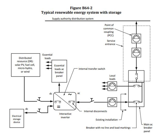
64-000 SCOPE (SEE APPENDIX B)
1) This Section applies to the installation of           Δ Rule 64-000
renewable energy systems except where the                Figures B64-1 and B64-2 illustrate typical renewable
voltage and current are limited in accordance with       energy systems and the various terms and circuits
Rule 16-200 1) a) and b).                                referenced in this Section.

2) This Section supplements or amends the
general requirements of this Code.

                                                     2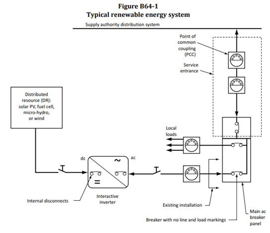
64-002 SPECIAL TERMINOLOGY
(SEE APPENDIX B)
In this Section, the following definitions shall apply:

AC module — a complete, environmentally protected assembly of interconnected solar cells, an
inverter, and other components designed to generate ac power from sunlight.

AC module
AC modules do not provide access to the photovoltaic output circuit that is internally connected to the
power conditioning unit. The output of an ac module is then referenced as the power conditioning unit
output.

Array — a mechanical integrated assembly of photovoltaic modules with a support structure and

                                                          3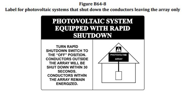
foundation, tracking, and other components as required to form a power-producing unit.

Auxiliary grounding electrode — a grounding electrode that augments equipment grounding and that is
not required to be directly connected to the electrode(s) that makes up the grounding electrode
system.

Bipolar system — a solar photovoltaic system that has two monopole photovoltaic source or output
circuits, each having opposite polarity to a common reference point or centre tap.

Controller —

Charge controller — equipment that controls dc voltage or dc current, or both, and that is used to
charge a battery or other storage device.

Diversion charge controller — equipment that regulates the charging process of a battery or other
storage device by diverting energy to ballast loads or to an interconnected supply authority service.

Diversion load controller — equipment that regulates the output of a generator by diverting energy
from the generator to ballast loads or to an interconnected utility service.

Dump load controller — equipment that regulates the output power of a micro-hydropower system
by adjusting the amount of energy flowing into the ballast load to compensate for main load
variations (e.g., in stand-alone systems) and prevent generator overvoltage.

Electronic governor — equipment that regulates the output power of a micro-hydropower system by
adjusting power flowing into the ballast load to compensate for main load variations (used only in
stand-alone systems).

Δ Guy wire — a wire rope not intended to conduct electricity that mechanically supports a wind turbine
tower

Interactive system — a power production system that operates in parallel with and can deliver power
to another system, such as a supply authority system.

Δ Inverter —
Combination inverter/power conditioning unit (PCU) — equipment that is used to invert direct
current into alternating current either at a fixed voltage and frequency in a stand-alone system or
following an imposed waveform in an interactive system.

Interactive inverter — an inverter whose ac output is intended for use in parallel with an electric
utility or other electricity supply authority network, whether or not the inverter injects net power
into the utility or supply network.

                                                     4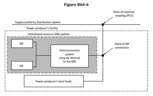
Δ Inverter
Inverters that are connected to the grid may incorporate a power conditioning unit (PCU) that improves
power quality in order to deliver voltage at a proper level and with proper characteristics. Users of this
Code should refer to CSA C22.2 No. 107.1, Clause 14, which provides additional information on the
requirements for interactive inverters.

Power conditioning unit (PCU) — equipment that is used to change voltage level or waveform or
otherwise alter or regulate the output of a power source.

Inverter input circuit — the insulated conductors between
a) the inverter and the battery in stand-alone systems; or
b) the renewable energy source and the inverter.

Inverter output circuit — the insulated conductors between
a) the inverter and a panelboard for stand-alone systems; or
b) the inverter and the service equipment or another electric power production source, such as a
supply authority

Load —

Ballast load — see Diversion load.

Diversion load — a resistive device, usually consisting of water or air electric heating elements, to
which energy is diverted when more energy is generated than required.

Dump load — see Diversion load.

Photovoltaic combiner — an assembly of buses and connections that may contain overcurrent
protective devices, control apparatus, switches, or other equipment and that connects photovoltaic
source circuits or the outputs of other combiners together to create an output at higher current or
higher voltage, or both.

Δ Photovoltaic combiner

This is a general term that applies to both photovoltaic combiners and photovoltaic recombiners. It is used
where there is no need to make a distinction between the two.

Δ Photovoltaic module — a complete, environmentally protected assembly of interconnected solar cells.

Application Class A photovoltaic module — an unrestricted access module for use in solar photovoltaic
systems operating in excess of 50 V dc or in excess of 240 W.

Application Class B photovoltaic module — a restricted access module for use in solar photovoltaic

                                                     5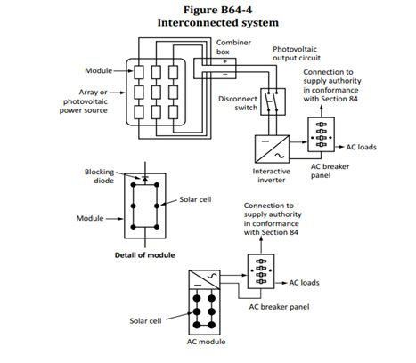
systems where the module is inaccessible to the public.
ApplicationClassCphotovoltaicmodule — a limited voltage, unrestricted access module for use in photovoltaic
systems operating at 50 V dc or less and 240 W or less.

Photovoltaic output circuit — circuit insulated conductors or cables between the photovoltaic source
circuit(s) and the power conditioning unit or dc utilization equipment.

Photovoltaic power source — an array or aggregate of arrays that generates dc power at system voltage
and current.

Δ Photovoltaic recombiner — an assembly of buses and connections that may contain overcurrent
protective devices, control apparatus, switches, or other equipment and that connects outputs from
photovoltaic combiners together to create an output at higher current or higher voltage, or both.

Δ Photovoltaic recombiner

This term is specific to photovoltaic recombiners and is used where the requirements for a photovoltaic
recombiner differ from those for a photovoltaic combiner.

Photovoltaic source circuit — insulated conductors or cables between photovoltaic modules and from
photovoltaic modules to the common connection point(s) of the dc system.

Point of common coupling — the point where the supply authority’s system is connected to the power
producer’s facilities or conductors.

                                                    6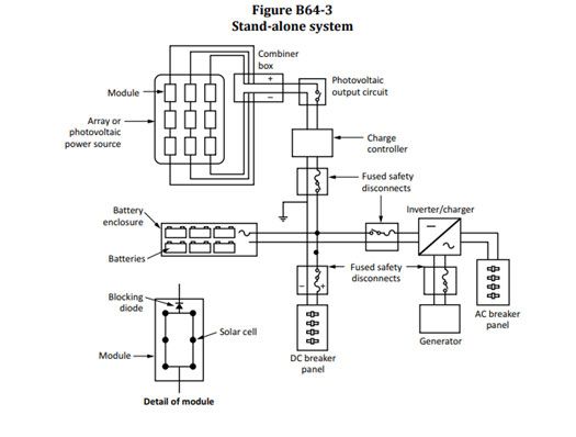
Point of distributed resource connection — the point where the renewable energy system is connected
to a different system, and that can be the same as the point of common coupling or, in the case of a stand-
alone system, the point at which the stand-alone network or load is connected to the renewable energy
system.
Power conditioning unit (PCU) — see Inverter.
Power conditioning unit output circuit — see Inverter output circuit.
Renewable energy — energy derived from resources that are naturally replenished, such as sunlight,
wind, water, tides, and geothermal heat.
Renewable energy system — a complete assembly consisting of equipment that converts renewable
energy into electrical energy suitable for connection to a utilization load.
Renewable energy systems
Renewable energy systems may be stand-alone or interactive with other electrical power production
sources and may be with or without electrical energy storage such as batteries.
Solar cell — the basic photovoltaic device that generates electricity when exposed to light.
Solar photovoltaic system — all the components and subsystems that in combination convert solar
energy into electrical energy suitable for connection to a utilization load.
Stand-alone system — a system that supplies power independently of a supply authority’s electrical
production and distribution network.
Δ Supply wiring — the insulated conductors or cables used to connect the renewable energy system to
its electrical point of delivery, which can include an alternator, integrated rectifier, controller or inverter or
both, or batteries.
APPENDIX B: RULE 64-002
Figures B64-3 to B64-5 illustrate typical solar photovoltaic systems, showing the various terms and
circuits referenced. Different inverters may require different photovoltaic array and wiring configurations.
These configurations may be divided into two groups: a) a floating array (as shown in the illustration of an
interconnected system in Figure B64-4) that requires a 2-pole disconnect switch; and b) a grounded array
that requires a single-pole disconnect switch, except for a 3-wire neutral grounded array that requires a
2-pole disconnect switch to interrupt both ungrounded conductors.
7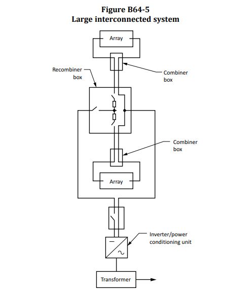
8

GENERAL
64-050 GENERAL
A renewable energy system shall be permitted to supply a building or other structure in addition to any
service(s) from another supply system(s).

64-052 INSULATED CONDUCTORS OF DIFFERENT SYSTEMS
(SEE APPENDIX B)
Insulated conductors of renewable energy systems shall be separated from different systems in accordance
with Rules 12-904 2) and 12-3030.

Rule 64-052

For the purpose of this Rule, multiple inverters and associated components connected to the same
renewable energy source are considered as one power generation source, and associated wiring may be
contained in the same raceway.

                                                   9
64-054 COMMON RETURN CONDUCTOR
For a renewable energy power source that has multiple supply circuit voltages and employs a common
return conductor, the ampacity of the common return conductor shall not be less than the sum of the
ampere ratings of the overcurrent devices of the individual supply circuits.
64-056 BIPOLAR SYSTEMS
1) Where the sum, without consideration of polarity, of the voltages of the two monopoles of a bipolar
system exceeds the voltage rating of the insulated conductors and connected equipment, the monopoles
shall be physically separated, and the electrical output circuits from each monopole shall be installed in
separate raceways until they are connected to the inverter.
2) The disconnecting means and overcurrent protective devices for each monopole output circuit shall be
in separate enclosures.
3) Notwithstanding Subrule 2), equipment rated for the maximum voltage between circuits and containing
a physical barrier separating the disconnecting means for each monopole shall be permitted to be used
instead of disconnecting means in separate enclosures.
4) All insulated conductors from each separate monopole shall be routed in the same raceway.
5) Bipolar systems shall be clearly marked with a permanent, legible warning notice, indicating that the
disconnection of the grounded conductor(s) may result in overvoltage on the equipment.
64-058 Overcurrent protection (see Appendix B)
1) Circuits connected to more than one electrical source shall have overcurrent devices located so as to
provide overcurrent protection from all sources.
2) Overcurrent protection for a transformer with a source(s) on each side shall be provided in accordance
with Section 26 by considering first one side of the transformer, then the other side of the transformer, as
the primary.
Δ 3) Overcurrent devices used in any dc portion of a renewable energy power system shall be marked for
the purpose.
4) Overcurrent devices such as circuit breakers, if backfed, shall be suitable for such operation.
Rule 64-058 4)
Circuits connected to more than one electrical source shall have overcurrent devices located so as to
provide overcurrent protection from all sources.
Overcurrent protection for a transformer with a source(s) on each side shall be provided in accordance
10with Section 26 by considering first one side of the transformer, then the other side of the transformer, as
the primary.
64-060 Disconnecting means (see Appendix B)
Rule 64-060
Because photovoltaic modules are energized while exposed to light, the installation, replacement, or
servicing of array components while the photovoltaic modules are irradiated may expose persons to the
hazard of electric shock. It is intended that means will be provided to isolate and disable portions of an
array or photovoltaic module that may require servicing. An opaque covering is an acceptable means of
disabling the array.
1) A disconnecting means shall be provided to disconnect simultaneously all ungrounded conductors
supplied from a renewable energy power supply source from all other insulated conductors in a building
or other structure.
Δ 2) The disconnecting means referred to in Sub-rule 1) shall
a) be capable of being energized from both sides;
b) indicate whether it is in the open or closed position;
c) have provision for being locked in the open position;
d) conform to Section 14;
e) be capable of being opened at rated load;
f) be capable of being closed with a fault on the system; and
g) be located within sight of and within 9 m of the equipment or be integral to the equipment.
3) Where the disconnecting means referred to in Sub-rule 1) is used as the service disconnecting means,
it shall be suitable for service entrance equipment.
4) A disconnecting means shall be provided to disconnect equipment such as inverters, batteries, and
charge controllers from all ungrounded conductors of all sources.
5) The disconnecting means required by this Rule shall not be connected in any grounded conductor if
operation of that disconnecting means would cause the grounded conductor to be in an ungrounded and
energized state.
6) Where the equipment is energized from more than one supply source, the disconnecting means shall
comply with Rules 14-414 and 14-700.
7) Output circuits rated 48 V and greater shall have means to disable and isolate them.
8) Disconnecting means shall be provided to disconnect a fuse from all sources of supply if the fuse is
11energized from both directions, as required by Rule 14-402.
Rule 64-060 8)
The required disconnecting means is to ensure complete isolation when fuses that could be energized
from both sides are being removed.
Δ 9) Disconnecting means provided on dc circuits shall be marked for the purpose.
10) The disconnecting means shall bear a warning to the effect that the terminals on both the line and load
sides could be energized when the disconnecting means is open.
Rule 64-060 10)
It is intended by this Sub-rule that the following or equivalent wording should be provided on or adjacent
to the disconnecting means: WARNING: ELECTRIC SHOCK HAZARD. DO NOT TOUCH TERMINALS.
TERMINALS ON BOTH THE LINE AND LOAD SIDES MAY BE ENERGIZED IN THE OPEN POSITION.
11) The disconnecting means for a hydrokinetic power system shall be permitted to be located beyond the
limits defined in Sub-rule 2), provided that it is capable of being locked in the open position.
12) For installations with combiners, a single disconnecting means capable of being opened at the ampere
rating of its photovoltaic output circuit in accordance with Rule 64-206 shall be installed for the photovoltaic
output circuit as follows:
a) for photovoltaic combiners equipped with fuses protecting photovoltaic source circuits, the
disconnecting means shall be i) integral with the photovoltaic combiner and interlocked with the door; or
ii) installed within 2 m of the photovoltaic combiner and interlocked with the combiner door; and
Δ b) for photovoltaic combiners equipped with circuit breakers protecting photovoltaic source
circuits, the disconnecting means shall be integral with the photovoltaic combiner or located not more
than 2 m from each photovoltaic combiner.
Rule 64-060 12)
The intent of this Rule is to have a disconnecting means for the output circuit of a photovoltaic combiner
capable of making and interrupting its full load rating and that may be opened with safety to the operator
with a fault on the system.
Δ 13) Notwithstanding Sub-rules 6) and 12), for installations with recombiners, where the recombiner is
installed in excess of 7.5 m from the inverter, a single disconnecting means capable of being opened at the
ampere rating of the inverter input circuit in accordance with Rule 64-206 shall be installed for the inverter
input circuit as follows:
a) for photovoltaic recombiners equipped with fuses protecting photovoltaic output circuits, the
disconnecting means shall be
i) integral with the photovoltaic recombiner and interlocked with the door; or
12ii) installed within 2 m of the photovoltaic recombiner and interlocked with the recombiner door; and
b) for photovoltaic recombiners equipped with circuit breakers protecting photovoltaic output circuits,
the disconnecting means shall be
i) integral with the photovoltaic recombiner; or
ii) located not more than 2 m from each photovoltaic recombiner.
64-062 Wiring methods
Δ 1) Except as provided for by Rule 64-210, insulated conductors for dc renewable energy sources or
supply circuits of an interactive inverter, installed inside a building or structure, shall be contained in
metallic raceways, metal enclosures, or cables with a metal armour or metal sheath.
2) Wiring methods as required by Sub-rule 1) shall be provided from the point of penetration of the surface
of the building or structure to the first readily accessible disconnecting means.
64-064 System grounding (see Appendix B)
Rule 64-064
Inverters used in renewable energy power systems usually contain a transformer that isolates the dc
grounded circuit conductor from the ac grounded circuit conductor. This isolation necessitates that both
a dc and ac grounding system be installed. The two grounding systems are bonded together or have a
common grounding electrode so that all ac and dc grounded circuit conductors and equipment grounding
conductors have the same near-zero potential to earth.
1) AC systems shall be grounded in accordance with Rule 10-206 1).
2) For renewable energy dc supply circuits, one conductor of a 2-wire system with a system voltage of 50
V or greater shall be grounded.
3) For renewable energy dc supply circuits, the reference (centre tap) conductor of a bipolar system shall
be grounded.
4) The dc supply circuits referred to in Sub-rules 2) and 3) shall be provided with a ground fault protection
device or system that
a) detects a ground fault;
b) indicates that a ground fault has occurred; and
c) interrupts the fault current by either
i) automatically disconnecting all conductors of the dc supply circuit or of the faulted portion of the dc
supply circuit; or
13ii) automatically causing the inverter or charge controller connected to the faulted circuit to cease
supplying power to the output circuits.
5) The dc circuit grounding connection shall be made at any single point on the renewable energy supply
circuit and shall be located as close as practicable to the supply source.
6) A renewable energy dc supply system equipped with a ground fault protection device shall be permitted
to have the grounding conductor connected to the grounding electrode via the ground fault protection
device.
Rule 64-064 6)
A renewable energy DC supply system equipped with a ground fault protection device is permitted to have
the required grounded conductor connected to the ground via the ground fault protection device.
Where this connection is internal to the ground fault equipment, it is not duplicated by an external
connection.
7) Where the connection permitted in Sub-rule 6) is internal to the equipment equipped with a ground fault
protection device, it shall not be duplicated by an external connection.
64-066 Ungrounded renewable energy power systems
(See appendix b)
Δ 1) Notwithstanding Rule 64-064, renewable energy power systems shall be permitted to operate with
ungrounded source and supply circuits where the system complies with the following:
a) all source and supply circuit conductors shall have overcurrent protection except as permitted by Rule
64-214 1);
b) the renewable energy power source shall be labeled in a conspicuous, legible, and permanent manner
with a suitable warning at each junction box, disconnecting means, and device where the ungrounded
circuits can be exposed during service;
Rule 64-066 1) b)
It is intended by this Item that the following or equivalent wording should be provided on or adjacent to
the disconnecting means:
WARNING: ELECTRIC SHOCK HAZARD. THE CONDUCTORS OF THIS RENEWABLE ENERGY POWER
SYSTEM ARE UNGROUNDED AND MAY BE ENERGIZED.
c) inverters or charge controllers used in systems with ungrounded source and supply circuits shall be
suitable for the purpose; and
d) all ungrounded dc systems shall be provided with a ground fault protection device or system that
i) detects a ground fault;
14ii) interrupts the fault current, if fault current can result from a single ground fault;
Rule 64-066 1) d) ii)
In an ungrounded dc system, a single ground fault will cause current to flow if there is another connection
to ground in the system and if there is no isolation between the grounding point and the ground fault. For
example, fault current will flow in a system in which a non-isolated inverter is connected to a grounded ac
system with a ground fault on the dc supply circuit.
iii) indicates that a ground fault has occurred; and
iv) either
A) automatically disconnects all conductors of the dc supply circuit or of the faulted portion of the dc
supply circuit; or
B) automatically causes the inverter or charge controller connected to the faulted circuit to cease
supplying power to inverter output circuits.
2) Notwithstanding Sub-rule 1), the renewable energy power system dc circuits shall be permitted to be
ungrounded where they are used with ungrounded battery systems that comply with Rule 64-800.
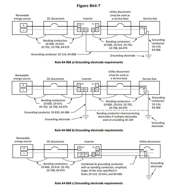
64-068 Grounding electrodes and grounding conductors
(see Appendix B)
AC and DC renewable energy power systems required to be grounded shall be connected to a grounding
conductor by one of the following means:
a) the dc grounding conductor and ac grounding conductor shall be connected to a single electrode, with
separate grounding conductors sized as required by Rule 10-114;
b) the dc grounding conductor shall be connected to a separate electrode by
i) the grounding conductor connected between the identified dc grounding point and a separate dc
grounding electrode; and
ii) bonding the dc grounding electrode to the ac grounding electrode where such bonding means is
required by Rule 10-104 b); or
c) a combined dc grounding conductor and ac equipment bonding conductor shall be
i) installed in accordance with Rule 10-116; and
ii) sized in accordance with Rule 10-114 or 10-614, whichever is larger.
bonding connection.
1516
64-070 Equipment bonding (see Appendix B)
Rules 64-070

Equipment bonding is required even in extra-low-voltage (12 and 24 V) systems not otherwise
required to have a system ground. A grounding electrode must be added to an ungrounded system
to accommodate equipment bonding. To maintain the shortest electrical time constant in each
dc circuit, the equipment bonding conductor should be routed as close as possible to the circuit
conductors. This facilitates the operation of overcurrent devices.

In many renewable energy systems, the bonding connection between the grounding conductor
and exposed conductive surfaces is located in the inverter or a dc power centre that may require
removal for service. In order to prevent shock and fire hazards, it is important that the bonding
continuity be maintained even when the equipment is removed.

Additional information regarding the grounding and bonding requirements for offshore hydrokinetic
systems may be found in IEEE 45.

The bonding connection between the grounding conductor and exposed conductive surfaces of
the renewable energy source or supply circuit equipment shall be made in such a manner that
disconnection or removal of the equipment will not interfere with or interrupt bonding continuity.

64-072 Marking
1) All interactive system(s) points of interconnection with other sources shall be marked with the
maximum ac output operating voltage and current.

2) The marking referred to in Sub-rule 1) shall be provided at the disconnecting means for each
interconnecting power source.

64-074 Warning notice and diagram (see Appendix B)
1) Any structure or building with a renewable energy power system that is not connected to a
supply service source and is a stand-alone system shall be marked in a conspicuous, legible,
and permanent manner to indicate the location of the system disconnecting means and that the
structure contains a stand-alone electrical power system.

2) Buildings and structures with both a utility supply service and a renewable energy system shall,
where practicable, have the disconnecting means grouped in accordance with Rule 6-102 2) or,
where such an arrangement is not practicable, shall have a permanent plaque posted on or near
each disconnecting means, indicating the location of all other service boxes supplying power to the
building, in accordance with Rule 6-102 3).

3) A permanent plaque or directory identifying all electrical power sources on or in the premises
shall be installed at each service equipment location and at the supply authority meter location.

4) Renewable energy power systems that store electrical energy shall be labeled in a conspicuous,
legible, and permanent manner with a suitable warning sign at the location of the service
disconnecting means of the premises.

                                                 17
Rule 64-074 4)
It is intended by this Sub-rule that the following or equivalent wording should be provided on or
adjacent to the disconnecting means:
WARNING: RENEWABLE ENERGY SYSTEM CONTAINS ELECTRICAL ENERGY STORAGE
DEVICES.
64-076 Interconnections to other circuits (see Appendix B)
Rule 64-076
For the type of connection described in this Rule, the switching equipment ensures isolation
because the system is a non-grid-interactive renewable energy system and does not export any
power to the supply system.
Where an installation is supplied from a renewable energy system that is not intended to be
interconnected with a supply authority, the switching equipment controlling the systems shall be
constructed or arranged so that it will be impossible to accidentally switch on power from one
source before power from another has been cut off.
64-078 Loss of interactive system power (see Appendix B)
1) The renewable energy system shall
a) be provided with a means of detecting when the electrical production and distribution network
has become de-energized; and
b) not feed the electrical production and distribution network side of the point of common
coupling during this condition.
2) The renewable energy system shall remain in the state described in Sub-rule 1) until the normal
voltage and frequency of the supply authority system have been restored.
Rule 64-078 2)
To ensure system stability of the grid and the restoration of normal voltage and frequency, the
supply authority may specify a delay period.
3) A normally interactive renewable energy system shall be permitted to operate as a stand-alone
system to supply loads that have been disconnected from electrical production and distribution
network sources.
INVERTERS
64-100 Maximum circuit loading (see Appendix B)
Δ Rule 64-100
Both stand-alone and interactive inverters are power-limited devices. Output circuits connected
18to these devices are sized on the continuous rated outputs of these devices and are not based on
load calculations or battery banks, if any. Some inverters may have specifications listing sustained
maximum output currents, and the higher of this number or the rated output should be used.
1) The maximum current of the inverter output circuit shall be the inverter continuous output
current rating.
2) The maximum current of a stand-alone inverter input circuit shall be the stand-alone continuous
inverter input current rating when the inverter is producing rated power at the lowest input voltage.
3) Renewable energy system maximum current ratings shall be based on continuous operation.
64-102 Stand-alone systems (see Appendix B)
The premises wiring system and the wiring on the supply side of the building or structure
disconnecting means shall comply with the applicable requirements of this Code, except as
follows:
a) the ac inverter output from a stand-alone system shall be permitted to supply ac power to the
building or structure disconnecting means at current levels below the rating of that disconnecting
means, provided that the inverter output rating is equal to or greater than the connected load of
the largest single utilization equipment connected to the system;
Rule 64-102 a)
A stand-alone residential or commercial renewable energy installation may have an ac output and
be connected to a building electrical system in compliance with all the Rules of this Code. Even
though such an installation may have service entrance equipment rated at 100 or 200 A at 120/240
V, there is no requirement that the renewable energy source provide either the rated full current
or the dual voltages of the service equipment. While safety requirements mandate full compliance
with this Code, a renewable energy installation is usually designed so that the actual ac demands
on the system are sized to the output rating of the renewable energy system.
b) the circuit conductors between the inverter output and the building or structure disconnecting
means shall be
i) sized based on the output rating of the inverter; and
ii) provided with overcurrent protection located at the output of the inverter, in accordance with
Section 14; and
c) the inverter output of a stand-alone renewable energy system shall be permitted to supply 120
V to single-phase, 3-wire, 120/240 V service equipment or distribution panels, provided that
i) there are no 240 V loads;
ii) there are no multi-wire branch circuits;
Rule 64-102 c) ii)
Multi-wire branch circuits are common in one- and two-family dwelling units. When these multi-
wire branch circuits are connected to a normal 120/240 V ac service, the currents in the neutral
conductors of the circuits (typically Nos. 14 to 3 AWG) subtract or are, at most, no larger than
19the rating of the branch circuit overcurrent device. When these electrical systems are connected
to a single 120 V renewable energy power system inverter by paralleling the two ungrounded
conductors in the service entrance load centre, the currents in the neutral conductor for each
multi-wire branch circuit add rather than subtract. The currents in the neutral conductors may be
as high as twice the rating of the branch circuit overcurrent device. With this configuration, neutral
conductor overloading is possible.
iii) the rating of the overcurrent device connected to the output of the inverter does not exceed
the rating of the neutral bus in the service equipment; and
iv) the equipment is marked in a conspicuous, legible, and permanent manner with a warning
not to connect it to multi-wire branch circuits.
Rule 64-102 c) iv)
It is intended by this Item that the following or equivalent wording should be provided on or
adjacent to the disconnecting means:
WARNING: SINGLE 120 V SUPPLY. DO NOT CONNECT MULTI-WIRE BRANCH CIRCUITS.
Δ 64-104 Interactive inverters mounted in locations that are not
readily accessible
Interactive inverters shall be permitted to be mounted on roofs or other exterior areas that are not
readily accessible, provided that
a) a dc and ac disconnecting means is provided in accordance with Rule 64-060 2);
b) an additional ac disconnecting means for the inverter is provided in accordance with Rule 84-
020;
and
c) a diagram is installed in accordance with Rule 84-030 2).
Δ 64-106 Connection to other sources (see Appendix B)
Δ Rule 64-106
An inverter or an ac module in an interactive renewable energy system should automatically
de-energize its output to the connected electrical production and distribution network upon
loss of voltage in that system and should remain in that state until the electrical production and
distribution network voltage has been restored. A renewable energy system that is normally
interactive may be permitted to operate as a stand-alone system to supply loads that have been
disconnected from an electrical production and distribution network source.
Marking requirements for interactive inverters are given in CSA C22.2 No. 107.1 and CAN/
CSA-C22.2 No. 62109.
20Only inverters and ac modules marked as interactive shall be permitted in interactive systems.
64-108 Ampacity of neutral conductor
1) The inverter output rating and maximum load connected between the neutral and any one
ungrounded conductor shall not exceed the ampacity of the neutral conductor, where an inverter
with a single-phase, 2-wire output is connected to the neutral and only one ungrounded conductor
of
a) a single-phase, 3-wire system; or
b) a three-phase, 4-wire wye-connected system.
Δ 2) A conductor used solely for instrumentation, voltage detection, or phase detection, and
connected to a single-phase or three-phase interactive inverter, shall be
a) permitted to be sized at less than the ampacity of the other current-carrying conductors; and
b) in no case smaller than the bonding conductor required by Rule 10-614.
Δ 64-110 Unbalanced interconnections (see Appendix B)
Δ Rule 64-110
Supply authority standards typically specify voltage balance requirements. The voltage unbalance
limit usually allowed in accordance with supply authority requirements is approximately 2 to
3%. For interactive single-phase inverters, unbalanced voltages can be minimized by the same
methods that are used for single-phase loads on a three-phase power system. See ANSI/C84.1-
2011.
1) Single-phase inverters for renewable energy systems and ac modules in interactive renewable
energy systems shall not be connected to three-phase systems unless the interactive system
a) is designed such that under normal operating conditions, the resulting three-phase system
voltages are balanced within the limits of supply authority requirements; and
b) complies with Rules 84-008 and 84-018.
2) Three-phase inverters and three-phase ac modules in interactive systems shall have all phases
automatically de-energized upon loss of the system voltage in one or more phases.
Δ 64-112 Interactive point of connection (see Appendix B)
1) The output of an interactive inverter or power conditioning unit shall be connected to the supply
authority system in accordance with Section 84.
2) Except as provided for in Sub-rule 3), the output of an interactive inverter described in this
Section shall be connected to the supply side of the service disconnecting means.
3) The output of an interactive inverter shall be permitted to be connected to the load side of the
service disconnecting means of the other source(s) at any distribution equipment on the premises
under the provisions of Sub-rule 4).
214) Where distribution equipment such as switchboards or panelboards located on the premises
is supplied simultaneously by a primary power source and one or more interactive inverters and
where the distribution equipment connected as permitted by Sub-rule 3) is capable of supplying
multiple branch circuits or feeders, or both, provisions for interconnection between the primary
power supply source and the interactive inverter(s) shall comply with the following conditions:
a) each source interconnection shall be made at a dedicated circuit breaker or fusible
disconnecting means;
b) each panelboard, busbar, or conductor supplied by the multiple sources in the interactive
system shall be provided with
i) suitable warning signs adjacent to each source disconnecting means to indicate that all of
the disconnecting means must be opened to ensure complete de-energization of the equipment in
accordance with Rule 14-414;
ii) the point of connection positioned at the opposite (load) end from the input feeder location or
main circuit location, where the panelboard is rated less than the sum of the ampere ratings of all
overcurrent devices in source circuits supplying the panelboard; and
iii) a permanent warning label at the distribution equipment to indicate that the overcurrent
device shall not be relocated;
Rule 64-112 4) b) iii)
It is intended by this Item that the following or equivalent wording should be provided on or
adjacent to the disconnecting means:
WARNING: INVERTER OUTPUT CONNECTION. DO NOT RELOCATE THIS OVERCURRENT
DEVICE.
c) notwithstanding Section 14, the sum of the ampere ratings of the overcurrent devices in source
circuits supplying power to a busbar or conductor shall be permitted to exceed the busbar or
conductor rating to a maximum of 120% of the rating of the busbar or conductor;
d) notwithstanding Section 14, for a dwelling unit, the sum of the ampere ratings of the
overcurrent devices in source circuits supplying power to a busbar or conductor shall be permitted
to exceed the busbar or conductor rating to a maximum of 125% of the rating of the busbar or
conductor; and
e) except as provided for in Sub-rule 5), the interconnection point shall be made on the line side
of all ground fault protection equipment.
5) The interconnection point described in Sub-rule 4) e) shall be permitted to be made on the load
side of ground fault protection equipment, provided that
a) there is ground fault protection for equipment from all ground fault current sources; and
b) ground fault protection devices used with supplies connected to the load side terminals are
suitable for back-feeding.
22Rule 64-112 5)
Load side connection of energy sources to commonly available ac ground fault circuit interrupters
and ac equipment ground fault protection circuit breakers may result in back-feed currents from
the renewable energy system output. Tests have shown that back-feed currents through these
devices may damage them and prevent operation.
SOLAR PHOTOVOLTAIC SYSTEMS
64-200 Marking (see Appendix B)
Rules 64-200 and 64-218
When a reflecting system is used for irradiance enhancement, increased levels of output power
may result. Marking of equipment should indicate the increased levels when such equipment is
used.
1) In addition to the marking requirements given in Rule 64-072, a permanent marking shall be
provided at an accessible location at the disconnecting means for the photovoltaic output circuit,
specifying the following:
a) the rated operating current and voltage;
b) the maximum photovoltaic source circuit voltage calculated in accordance with Rule 64-202 1)
and 2); and
c) the rated short-circuit current.
2) A photovoltaic system with rapid shutdown in accordance with Rule 64-218 shall be provided
with a permanent marking in an accessible location at the disconnecting means for the
photovoltaic output circuit stating that the photovoltaic system is equipped with rapid shutdown.
Δ Rule 64-200 2)
It is intended by this Sub-rule that the following or equivalent wording should be provided on or
adjacent to the disconnecting means for the photovoltaic output circuit:
PHOTOVOLTAIC SYSTEM EQUIPPED WITH RAPID SHUTDOWN.
3) A warning sign for a photovoltaic system shall be in capital letters with a minimum height of 9.5
mm, in white on a red background.
2364-202 Voltage of solar photovoltaic systems (see Appendix B)
1) The maximum photovoltaic source and output circuit voltage shall be the rated open-circuit
voltage of the photovoltaic power source multiplied by 125%.
Rule 64-202 1)
The 125% factor specified by Rule 64-202 is the temperature adjustment factor. The rating of
photovoltaic modules is based on the standard test conditions (an irradiance of 1000 W/m2 and an
ambient temperature of 25 °C). The voltage produced by the module increases as the temperature
decreases. The 125% factor is based on a minimum module temperature of – 40 °C.
2) Notwithstanding Sub-rule 1), the maximum photovoltaic source and output circuit voltage shall
be permitted to be calculated using
a) the rated open-circuit voltage of the photovoltaic power source;
b) the difference between 25 °C and the lowest expected daily minimum temperature; and
c) the voltage temperature coefficient as specified by the manufacturer.
Rule 64-202 2)
The lowest daily minimum temperature described in this Sub-rule is available from Environment
Canada, “Canadian Climate Normals”. Using the manufacturer’s temperature coefficient, the
maximum photovoltaic source circuit and output circuit voltage may be calculated using the
following formula:
VMPC = VOC × [1 + (TM – 25) × TK]
where
24TMI =I lowest daily minimum temperature in degrees Celsius
TKI =I temperature coefficient in per cent per degree Celsius
VOCI =I rated open-circuit voltage of the photovoltaic power source in volts
VMPCI =I maximum photovoltaic source circuit and output circuit voltage in volts
Example:
A solar photovoltaic system is installed in a geographic location where the lowest daily minimum
temperature (TM) is –18 °C. According to the manufacturer’s data, the temperature coefficient (TK)
is –0.25%/°C and the rated open-circuit voltage (VOC) is 92 V.
VMPC = 92 V × {1 + [(–18 °C – 25 °C) × –0.25%/°C]}
VMPC = 92 V × [1 + (– 43 × –0.0025)]
VMPC = 92 V × 1.1075
VMPC = 101.89 V
3) The maximum photovoltaic source and output circuit voltage shall be used to determine the
voltage ratings of insulated conductors, cables, disconnects, overcurrent protection, and other
equipment in photovoltaic source or output circuits.
4) The photovoltaic source and output circuits for installations in or on dwelling units shall be
permitted to have a voltage not exceeding 600 V dc, provided that
a) all energized parts in the photovoltaic source and output circuits over 150 volts-to-ground are
accessible only to qualified persons;
b) the photovoltaic source and output circuits are not connected as a bipolar system; and
c) the insulated conductors for photovoltaic source and output circuits over 30 V located inside
the building are contained in metallic raceways, metal enclosures, or cables with a metal armour or
metal sheath.
Δ 5) Photovoltaic source and output circuits, and equipment connected to or within those circuits,
with maximum voltages higher than 750 V dc but not exceeding 1500 V dc shall not be required to
comply with Rules 36-204, 36-208, and 36-214, provided that
a) the installation is serviced only by qualified persons;
b) the part of the installation exceeding 750 V dc is inaccessible to the public; and
c) enclosures in which photovoltaic source and output circuits exceeding 750 V dc are present are
marked with the word “DANGER” followed by the maximum rated photovoltaic circuit voltage of
the equipment.
Δ Rule 64-202 5) c)
“DANGER 1500 V dc” is an example of the marking required by Sub-rule 5) c) for a system
operating at a 1500 V dc maximum photovoltaic circuit voltage. Photovoltaic source and output
25circuits and equipment connected to or within those circuits are considered inaccessible where
they are located within a fenced enclosure in accordance with Rule 26-300, guarded by locked
doors, elevated 3 m or more above grade level or above any surface that a person can stand on, or
where access is restricted by other effective means.
64-204 Voltage drop
Notwithstanding the requirements of Rule 8-102, photovoltaic output circuit and photovoltaic
source circuit conductors shall meet one of the following requirements:
a) the voltage drop shall be considered acceptable where the conductors are rated not less than
125% of the maximum available short-circuit current of the solar photovoltaic system;
b) the voltage drop shall not exceed 5% of the rated operating voltage;
c) the rated operating voltage drop shall not exceed the percentage calculated by multiplying
50% of the rated current of the photovoltaic source circuit under consideration divided by the rated
current of the entire array connected to the power conditioning unit or directly connected loads;
or
d) the resistance shall be sufficiently low to facilitate the operation of the overcurrent device
protecting the circuit in the event of a short-circuit.
64-206 Ampere rating of photovoltaic source and output circuits The ampere rating of a
photovoltaic source and output circuit shall be
a) the ampere rating of the overcurrent device protecting the circuit or the ampacity of the
conductors, whichever is less; and
b) not less than 125% of the rated short-circuit current of that photovoltaic source’s circuit.
64-208 Photovoltaic module application class use (see Appendix
B)
Δ Rule 64-208
For the application of this Rule, photovoltaic modules are considered inaccessible to the public
where they are located within a fenced enclosure in accordance with Rule 26-300, guarded by
locked doors, elevated 3 m or more above grade level or above any surface that a person can stand
on, or where access is restricted by other effective means.
For the application of this Rule, modules without an application class marking are considered to be
application Class A.
1) Photovoltaic modules marked with application Class A or C shall be permitted to be installed in a
location accessible to the public.
2) Photovoltaic modules marked with an application Class B shall not be permitted for installations
accessible to the public. 64-210 Wiring method (see Appendix B)
2664-210 Wiring method (see Appendix B)
Δ Rule 64-210
Most photovoltaic modules do not have provision for attaching raceways. These circuits may
have to be made not readily accessible by physical barriers such as metal screening, elevation, or
fencing. Photovoltaic modules operate at elevated temperatures when exposed to high ambient
temperatures and to bright sunlight. These temperatures may routinely exceed 70 °C in many
locations. Module interconnection insulated conductors and cables are available with insulation
rated for wet locations and a temperature rating of 90 °C or greater.
1) Notwithstanding Rule 12-102 3), flexible cords suitable for extra-hard usage shall be permitted for
the interconnection of photovoltaic modules within an array.
Δ 2) Notwithstanding Rule 12-204 4), cables included as part of photovoltaic modules shall be
permitted for the interconnection of photovoltaic modules within an array, provided that the
photovoltaic source and output circuits operate at a maximum system voltage
a) of 30 V or less; or
b) greater than 30 V where the array is not installed in readily accessible locations.
3) Notwithstanding Rule 12-204, Type RPVU cables shall be permitted for the interconnection of
photovoltaic modules within an array, provided that
a) the installation is serviced only by qualified persons; and
b) the installation is inaccessible to the public.
4) Insulated conductors and cables installed in accordance with Sub-rules 1), 2), and 3) shall be
adequately protected against mechanical damage during and after installation, and supported by
straps or other devices located
a) within 300 mm of every box or connector; and
b) at intervals of not more than 1 m throughout the run.
Rule 64-210 4)
The intent of Sub-rule 4) is to protect solar photovoltaic cable from mechanical damage, including
rubbing on surfaces such as roofing and array structures.
5) Where the dc arc-fault protection referred to in Rule 64-216 is not located at the module,
photovoltaic source circuit insulated conductors and cables installed on or above a building and
installed in accordance with Sub-rules 1), 2), and 3) shall be provided with mechanical protection
in the form of an enclosed raceway or other acceptable material to protect against damage from
rodents.
Rule 64-210 5)
The intent of Sub-rule 5) is to provide protection against damage from rodents by enclosing the
photovoltaic source circuit insulated conductors and cables in material such as expanded metal,
solid metal, and screening.
276) Notwithstanding Rule 12-2202 1), 2), and 3), Type RPVU cables shall be permitted to be installed
in cable tray for the interconnection of the solar photovoltaic system.
7) Type RPV conductors installed in a raceway shall be permitted for the interconnection of the
solar photovoltaic system.
8) Cables used for solar photovoltaic installations on or above a building shall meet the flame
spread requirements of the National Building Code of Canada or local building legislation.
Δ Rule 64-210 8)
Type RPVU cable with FT1 markings is suitable for installation on buildings.
9) Types RPV insulated conductors and RPVU cables installed inside a building or structure shall
be contained in a raceway.
10) Notwithstanding Rules 12-904 and 12-3030, junction boxes, enclosures, fittings, and raceways
or compartments of multiple-channel raceways shall be permitted to contain insulated conductors
of a single renewable energy system that are connected to different sources of voltage where
a) all conductors are insulated for at least the same voltage as that of the circuit having the
highest voltage; and
b) a suitable warning notice is placed at each enclosure and junction box giving access to the
insulated conductors, indicating where multiple photovoltaic source circuits and photovoltaic
output circuits are available within the junction boxes, enclosures, and raceways or compartments
of a multiple-channel raceway.
64-212 Insulated conductor marking or colour coding (see
Appendix B)
Rule 64-212
CSA C22.2 No. 271 requires the positive or negative identification on RPV or RPVU multi-conductor
cables to be “+/-”, “pos/neg”, or “positive/negative”. Single-conductor cables are permitted to be
marked in the same manner.
1) Notwithstanding Rule 4-032, dc photovoltaic output circuit insulated conductors, and
photovoltaic source circuit insulated conductors installed between a module and the power
conditioning unit of the dc system, shall be coloured or coded, or both, as follows:
a) for a 2-wire circuit
i) red for positive and black for negative; or
ii) black insulated conductors manufactured with permanent surface printing indicating the
polarity on the insulated conductor; and
b) for a 3-wire circuit (bipolar circuit)
i) white, grey, or white with a coloured stripe for the mid-wire (identified as the centre tap), red
28for positive, and black for negative; or
ii) black insulated conductors manufactured with permanent surface printing indicating the
polarity on the conductor insulation.
2) The requirements of Sub-rule 1) shall not be met by field marking or labeling.
3) Notwithstanding Sub-rule 2), insulated conductor colour coding for multi-conductor cables
required in Sub-rule 1) shall be permitted to be made through suitable field labeling or marking in a
permanent manner.
4) The insulated conductor labeling and marking permitted in Sub-rule 3) shall
Δ a) be made at every point where the separate insulated conductors are rendered accessible and
visible by removal of the outer jacket of the cable;
b) be made by painting or other suitable means; and
c) not render the manufacturer’s numbering of the insulated conductors illegible.
Δ 64-214 Overcurrent protection for apparatus and conductors
(see Appendix B)
1) Notwithstanding Rules 64-058 1) and 64-066 1) a), individual overcurrent protection devices shall
not be required where the sum of the available short-circuit current from all photovoltaic source
circuits connected to the same power conditioning unit is not greater than the rated ampacity of
the apparatus or conductors.
Rule 64-214 1)
Where there is no back-feed from a battery or inverter, the maximum short-circuit current that can
flow in any of the photovoltaic source circuits is the sum of the short-circuit current ratings of all
the other photovoltaic source circuits connected in parallel.
Example of a calculation where the short-circuit current ratings of all photovoltaic source circuits
are equal:
Maximum photovoltaic source circuit short-circuit current = (the sum of the short-circuit current
for all photovoltaic source circuits connected in parallel) minus (the short-circuit current for one of
the photovoltaic source circuits)
2) Where overcurrent protection is required by Rule 64-058 1) for a photovoltaic source circuit,
each photovoltaic source circuit shall be protected by an individual overcurrent device rated or set
at not more than the allowable ampacity of the conductors of the photovoltaic source circuit or the
29maximum overcurrent protection indicated on the photovoltaic module nameplate, whichever is
less.
3) Where the value as specified in Sub-rule 2) does not correspond to the standard rating of an
overcurrent device, the next higher standard rating shall be permitted.
4) Overcurrent devices for photovoltaic source circuits shall be accessible and shall be grouped
where practicable.
Δ 64-216 Photovoltaic DC arc-fault circuit protection
1) Solar photovoltaic systems with dc source circuits or output circuits, or both, and operating at a
maximum system voltage of 80 V or greater, shall be protected by
a) a dc arc-fault circuit interrupter; or
b) other system equipment that provides equivalent protection.
2) The protection required in Sub-rule 1) shall
a) detect and interrupt arcing faults resulting from a failure in the intended continuity of a
conductor, connection, photovoltaic module, or other system component in the dc photovoltaic
source and output circuits;
b) not have the capability of being automatically restarted;
c) have annunciation, without an automatic reset, that provides a visual indication that the circuit
interrupter has operated; and
d) disable or disconnect
i) inverters or charge controllers connected to the faulted circuit when the fault is detected;
or
ii) the photovoltaic dc source circuits or dc output circuits either within the combiner, at the
module junction box, or at the module cable connectors.
30Δ 64-218 Photovoltaic rapid shutdown (see Appendix B)
Rules 64-200 and 64-218
When a reflecting system is used for irradiance enhancement, increased levels of output power
may result. Marking of equipment should indicate the increased levels when such equipment is
used.
Δ Rule 64-218
The requirements for a photovoltaic rapid shutdown system are given in CSA C22.2 No. 330
1) Photovoltaic rapid shutdown shall be provided for a photovoltaic system installed on or in
buildings where the photovoltaic source or output circuit insulated conductors or cables installed
on or in buildings are more than 1 m from a photovoltaic array.
2) Notwithstanding Sub-rule 1), photovoltaic rapid shutdown shall not be required for ground-
mounted photovoltaic system circuits that enter a building whose sole purpose is to house
photovoltaic system equipment.
3) Photovoltaic rapid shutdown shall limit photovoltaic source or output circuits located more than
1 m from the photovoltaic array to not more than 30 V within 30 s of rapid shutdown initiation.
Rule 64-218 3)
The intent of Sub-rule 3) is to limit photovoltaic source or output circuits to not more than 30 V
within 30 s of rapid shutdown initiation, where the voltage and power are measured between any
two photovoltaic source or output circuit conductors, and between any photovoltaic source or
output circuit conductors and ground.
4) A device used to initiate photovoltaic rapid shutdown shall be readily accessible and located
a) for single dwelling units, at the supply authority meter location;
b) for other than single dwelling units, at the consumer’s service equipment or supply authority
meter location, and
i) at a permanent access to a building roof where an array(s) is installed; or
ii) within sight and within 9 m of the array(s); and
31c) for a stand-alone system, in accordance with Items b) i) and ii).
5) The location of the device used to initiate photovoltaic rapid shutdown shall be shown on the
diagram required in Rule 84-030 2).
6) A label indicating that the photovoltaic system is equipped with photovoltaic rapid shutdown
shall be installed at the supply authority meter location and at the consumer’s service equipment
location.
Δ 64-220 Attachment plugs and similar wiring devices (see
Appendix B)
Δ Rule 64-220
Photovoltaic connectors of the sleeve- and pin-type are approved for use as a mated pair only, i.e.,
the connectors are certified as a pair.
Each connector manufacturer uses materials and procedures to manufacture their connectors in a
proprietary manner. Although the connectors may look electrically and mechanically compatible,
there is no evaluation to ensure that the production process of one manufacturer will result in its
connectors being compatible with another’s.
1) Attachment plugs and similar wiring devices shall be permitted to connect cables between
photovoltaic modules, or between dc photovoltaic source and photovoltaic output circuits, where
a) there are no exposed energized parts, whether the devices are connected or disconnected;
b) the devices are polarized;
c) the devices have a configuration that is not interchangeable with receptacles or attachment
plugs of other systems on the premises;
d) the devices are of the locking type;
e) the devices are rated for the voltage and current of the circuit in which they are installed;
f ) the devices provide strain relief;
32You can also read