MTi 600-series Datasheet - Xsens
←
→
Page content transcription
If your browser does not render page correctly, please read the page content below

Document MT1603P, Revision 2020.A, Jun 2020

          MTi 600-series
              Datasheet
1                         www.xsens.com
        IMU, VRU, AHRS and GNSS/INS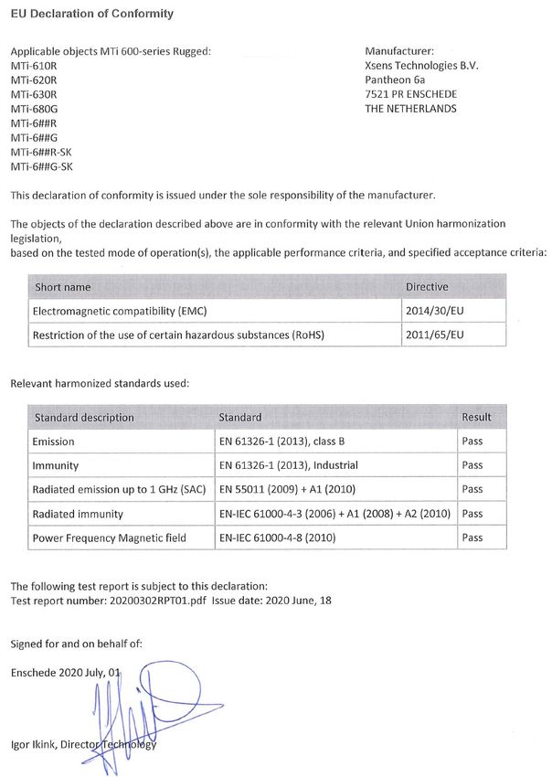
Revision                  Date                        By                          Changes
 A                         Sept. 2019                  AKO, MCR                    Initial release
 B                         Sep 2019                    AKO                         Grammar and
                                                                                   wording update
 C                         Nov 2019                    WBO, MCR                    Maximum output
                                                                                   current for the
                                                                                   SYNC output
 D                         Nov 2019                    AKO                         Xsens brand update
 2020.A                    Jun 2020                    AKO                         Added MTi-680G

© 2005-2020, Xsens Technologies B.V. All rights reserved. Information in this document is subject to change
without notice. Xsens, Xsens DOT, MVN, MotionGrid, MTi, MTi-G, MTx, MTw, Awinda and KiC are registered
trademarks or trademarks of Xsens Technologies B.V. and/or its parent, subsidiaries and/or affiliates in The
Netherlands, the USA and/or other countries. All other trademarks are the property of their respective owners.

                                                      2                                 www.xsens.com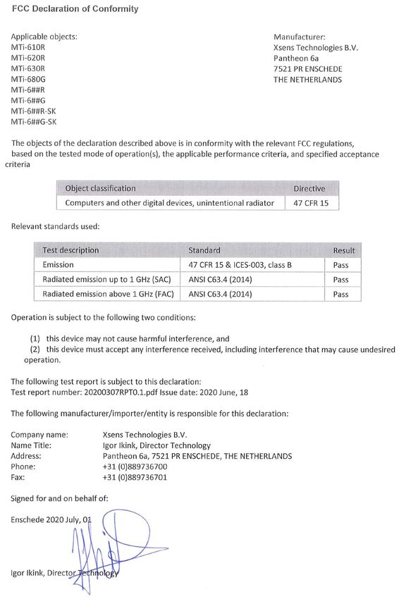
Table of Contents

1 General information .................................................................. 7
 1.1    Ordering information................................................................................... 8
 1.2    MTi 600-series architecture.......................................................................... 9
 1.3 MTi 600-series product variants ..................................................................10
   1.3.1 MTi-610 IMU .......................................................................................10
   1.3.2 MTi-620 VRU .......................................................................................10
   1.3.3 MTi-630 AHRS .....................................................................................11
   1.3.4 MTi-670 GNSS/INS ..............................................................................11
   1.3.5 MTi-680G RTK GNSS/INS ......................................................................11

2 Sensor specifications .............................................................. 12
 2.1    MTi 600-series performance specifications ....................................................12
 2.2    Sensor specifications .................................................................................13

3 Functional description ............................................................. 15
 3.1    Pin description module ...............................................................................15
 3.2    Pin description MTi-680G ............................................................................16
 3.3 Peripheral interfaces ..................................................................................17
   3.3.1 CAN (Controller Area Network) ..............................................................17
   3.3.2 RS232 with RTS/CTS flow control ...........................................................17
   3.3.3 UART..................................................................................................17
   3.3.4 RTCM input port ..................................................................................17

4 Signal processing and algorithms ........................................... 18
 4.1 Signal processing pipeline...........................................................................18
   4.1.1 Strapdown integration ..........................................................................18
   4.1.2 Xsens sensor fusion algorithm for VRU and AHRS product types ................18
   4.1.3 Xsens sensor fusion algorithm for the GNSS/INS product type ...................22
 4.2 Data output ..............................................................................................24
   4.2.1 Xbus output ........................................................................................24
   4.2.2 NMEA output .......................................................................................25
   4.2.3 CAN output .........................................................................................25
 4.3    GNSS input ...............................................................................................25
 4.4 Magnetic interference ................................................................................26
   4.4.1 Magnetic Field Mapping (MFM) ...............................................................26
 4.5    Frames of reference ...................................................................................26

5 Synchronization options .......................................................... 28
 5.1    Trigger signal ............................................................................................28

                                                         3                                   www.xsens.com
5.2 SyncIn .....................................................................................................29
    5.2.1 TriggerIndication function .....................................................................29
    5.2.2 SendLatest function .............................................................................29
    5.2.3 StartSampling function .........................................................................29
    5.2.4 Clock Bias Estimation function ...............................................................29
    5.2.5 1PPS Time-pulse function .....................................................................30
  5.3 SyncOut ...................................................................................................31
    5.3.1 Interval Transition Measurement function ...............................................31
  5.4     Combining multiple Sync functions ..............................................................31

6 System and electrical specifications ........................................ 32
  6.1     Interface specifications ..............................................................................32
  6.2     System specifications .................................................................................32
  6.3     Electrical specifications ...............................................................................34
  6.4     Absolute maximum ratings .........................................................................35

7 Design and packaging ............................................................. 36
  7.1     Design .....................................................................................................36
  7.2 Packaging information ................................................................................37
    7.2.1 MTi 600-series module .........................................................................37
    7.2.2 MTi-680G ............................................................................................38

8 Declaration of conformity ........................................................ 39
  8.1     EU Declaration of Conformity MTi-600 module ..............................................39
  8.2     EU Declaration of Conformity MTi-600 rugged ...............................................40
  8.3     FCC Declaration of Conformity MTi-600 module .............................................41
  8.4     FCC Declaration of Conformity MTi-600 rugged .............................................42

List of Tables
Table 1: MTi product documentation overview ........................................................... 7
Table 2: Ordering information for MTi 600-series products .......................................... 8
Table 3: Orientation performance specifications .......................................................12
Table 4: Position and velocity performance specifications for MTi-670-DK ....................12
Table 5: Position and velocity performance specifications for MTi-680G with RTK
correction signals provided ....................................................................................12
Table 6: MTi 600-series gyroscope specifications ......................................................13
Table 7: MTi 600-series accelerometer specifications ................................................13
Table 8: MTi 600-series magnetometer specifications ................................................13
Table 9: MTi 600-series barometer specifications ......................................................13

                                                           4                                    www.xsens.com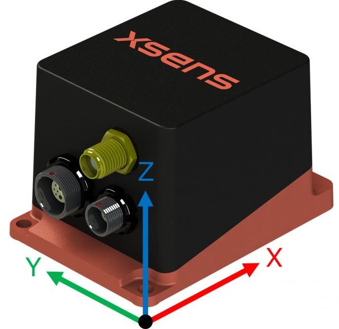
Table   10: MTi 600-series orthogonality specifications ................................................13
Table   11: MTi-680G GNSS specifications .................................................................14
Table   12: Pin descriptions of the MTi-600 ................................................................15
Table   13: Pin descriptions MTi-680G Host Interface ..................................................16
Table   14: Pin descriptions MTi-680G RTCM corrections ..............................................16
Table   15 RTCM input port baud rates ......................................................................17
Table   16: Filter profiles for MTi-620 and MTi-630 ......................................................19
Table   17: Heading Behaviour .................................................................................20
Table   18: Filter profiles for MTi-670 and MTi-680G (GNSS/INS)..................................23
Table   19: Output data rates ...................................................................................24
Table   20: Settings required to enable NMEAin for the MTi-670 ...................................25
Table   21: Generic synchronization parameters .........................................................28
Table   22: Remarks on combining multiple Sync functions ..........................................31
Table   23: Communication interfaces .......................................................................32
Table   24: System specifications of MTi 600-series modules ........................................32
Table   25: System specifications of MTi-680G ...........................................................32
Table   26: Supply voltage specifications ...................................................................34
Table   27: I/O electrical specifications ......................................................................34
Table   28: Absolute maximum ratings MTi 600-series module .....................................35

List of Figures
Figure   1: MTi 600-series module diagram ................................................................. 9
Figure   2: Pin configuration of the MTi 600-series module (bottom view) ......................15
Figure   3 Connectors and pin numbers on the MTi-680G housing .................................16
Figure   4: Filter profile and heading behaviour selection: a tiered approach ..................21
Figure   5: Lever-arm correction for MTi-680G ...........................................................23
Figure   6 Default sensor fixed coordinate system (Sxyz) for the MTi 600-series module ...27
Figure   7: Default sensor coordinate system for the MTi-680G.....................................27
Figure   8: Location origin of measurements MTi-600 module (dimensions in mm) ..........36
Figure   9: Location origin of measurements MTi-680G (dimensions in mm) ...................36

List of Abbreviations
The MT Family Reference Manual 1 provides a list of abbreviations used across our MT
documentation.

1The latest available documentation can be found in your MT Software Suite installation
folder or via the following link: https://xsens.com/xsens-mti-documentation

                                                         5                                  www.xsens.com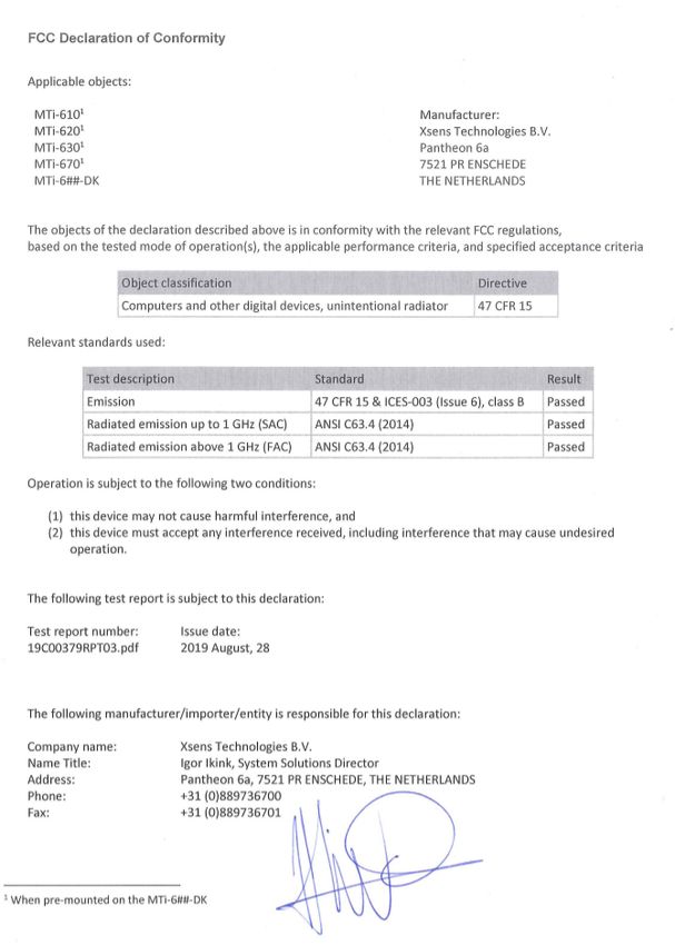
References
 Abbreviation     Description
 [FRM]            “MT Family Reference Manual”, document id MT1600P
 [LLCP]           “MT Low-Level Communication Protocol Documentation.pdf”, document id
                  MT0101P
 [MFM]            “Magnetic Field Mapper Documentation.pdf”, document id MT0202P
 [MTM]            “MT Manager User Manual.pdf”, document id MT0216P
 [CAN]            “MT CAN Protocol Documentation”, document ID MT1604P

Note: The latest available documentation can be found in your MT Software Suite
installation folder or via the following link: https://xsens.com/xsens-mti-documentation

                                               6                            www.xsens.com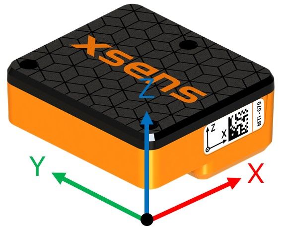
1 General information
This document provides information on the usage and technical details of the MTi 600-
series modules and the MTi-680G. The MTi 600-series module (MTi-600) is a fully
functional, self-contained module that is easy to design-in. The MTi-600 module can be
connected to a host through RS232, CAN or UART interfaces, or through USB using the
UART to USB converter (included in the MTi 600-series Development Kit). Whereas the
MTi-680G is a rugged device with integrated RTK GNSS receiver.

The MTi Family Reference Manual1 supplements this document. It reports generic
information on the MTi 1-series and MTi 600-series, such as output definitions, algorithm
details and installation tips.

The MTi 600-series Hardware Integration Manual2 supplements this document. In this
document, notes on typical application scenarios, printed circuit board (PCB) layout,
origin of measurement reference system, stress related considerations, reference designs
and handling information can be found.

For testing and prototyping, Xsens provides the MTi-630 and MTi-670 Development Kits
(MTi-630-DK and MTi-670-DK) as well as a Starter Kit for the MTi-680G (MTi-680G-SK).
In addition to the RS232, CAN and UART pin connectors of the MTi 600-series module,
the Development Kit offers a direct USB, RS232, RS422 and CAN interface. Technical
details of the Development Kit and its usage can be found in the MTi 600-series DK User
Manual1.

The MT Low Level Communication Protocol1 document provides a complete reference for
the protocols used to communicate with Xsens Motion Trackers on low-level basis. The
MT Low Level Communication Protocol document also describes the synchronization
messages and settings in detail.

Table 1 summarizes all available official documents for the Xsens MTi product line.

                           Table 1: MTi product documentation overview

            MTi 1-series                   MTi 600-series             MTi 10/100-series
                    MTi Family Reference Manual
      MTi 1-series Datasheet          MTi 600-series Datasheet
                                       MTi 600-series DK User
    MTi 1-series DK User Manual
                                               Manual
                                                                       MTi User Manual
                                         MTi 600-series HW
    MTi 1-series HW Integration          Integration Manual
               Manual                     MT CAN protocol
                                           Documentation
                                        MT Manager Manual
                                    Magnetic Calibration Manual
                        MT Low Level Communication Protocol Documentation
                                   Firmware Updater User Manual

2Links to the latest available documentation can be found via the following link: Xsens MTi
Documentation

                                                 7                              www.xsens.com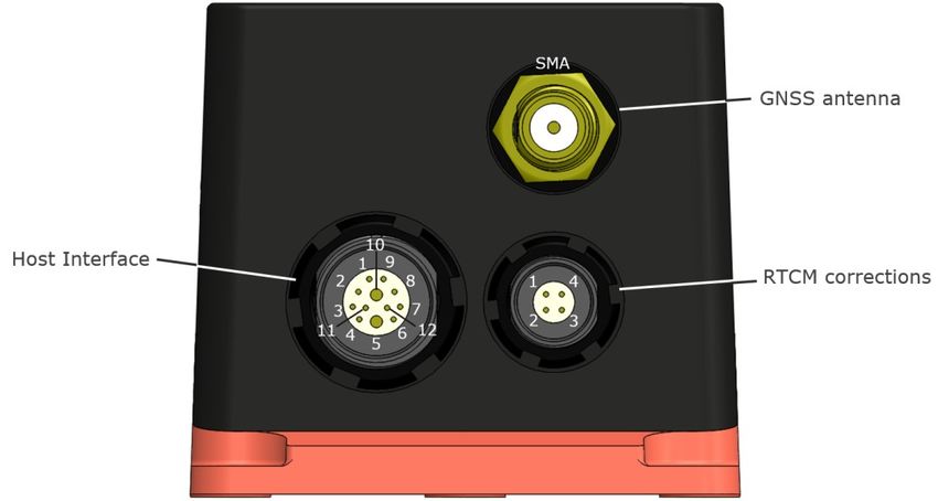
1.1 Ordering information

                  Table 2: Ordering information for MTi 600-series products

Part Number             Description                                   Packing
       MTi-610          IMU                                                   Box
                        Inertial data                                     (MOQ 5 units)
      MTi-620           VRU                                                   Box
                        Inertial data, roll/pitch/yaw                     (MOQ 5 units)
                        (unreferenced)
      MTi-630           AHRS                                                  Box
                        Inertial data, roll/pitch/yaw (referenced)        (MOQ 5 units)
      MTi-670           GNSS/INS                                              Box
                        Inertial data, roll/pitch/yaw (referenced),       (MOQ 5 units)
                        velocity, position
      MTi-680G          RTK GNSS/INS                                            Box
                        Inertial data, roll/pitch/yaw (referenced),
                        velocity, position
     MTi-630-DK         Development Kit for MTi-630 AHRS                        Box
                        (also applicable for MTI-610 IMU and
                        MTi-620 VRU)
     MTi-670-DK         Development Kit for MTi-670 GNSS/INS                    Box
    MTi-680G-SK         Starter Kit for MTi-680G RTK GNSS/INS                   Box

                                               8                                www.xsens.com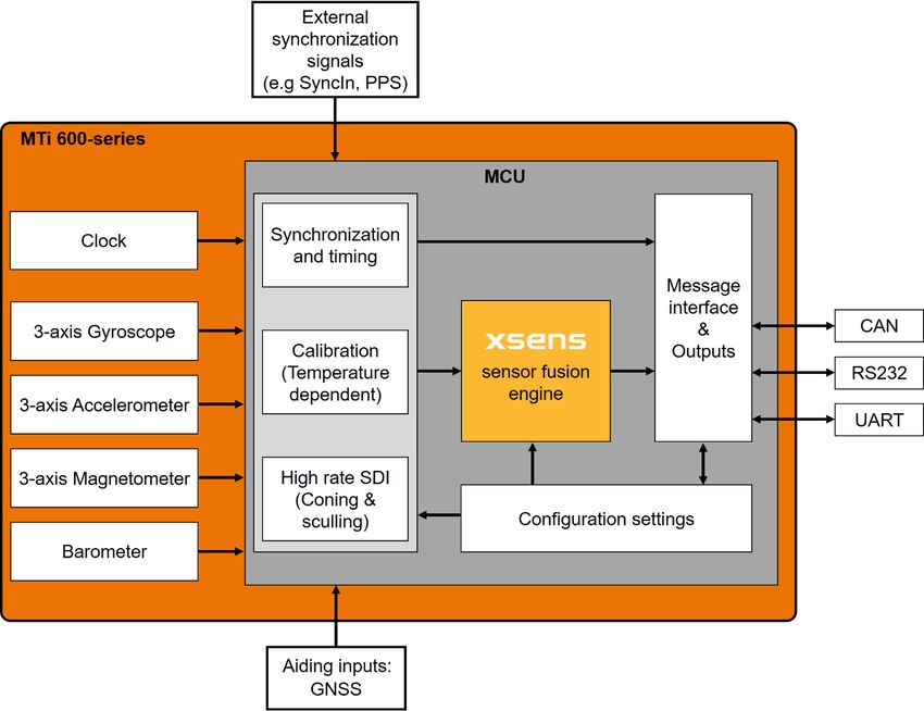
1.2 MTi 600-series architecture

                          Figure 1: MTi 600-series module diagram

The diagram in Figure 1 shows a simplified architecture of the MTi 6x0-series module.
The MTi-6x0 contains a 3-axis gyroscope, 3-axis accelerometer, 3-axis magnetometer,
barometer, a high-accuracy crystal and a low-power micro controller unit (MCU). The
MTi-670 module can also accept the signals from an external GNSS receiver. The MCU
coordinates the timing and synchronization of the various sensors. The module offers the
possibility to use external signals in order to accurately synchronize the clock and/or
outputs of the MTi-6x0 with any user application. The MCU applies calibration models
(unique to each sensor and including orientation, gain and bias offsets, plus more
advanced relationships such as non-linear temperature effects and other higher order
terms) and runs the Xsens optimized strapdown algorithm, which performs high-
rate dead-reckoning calculations up to 2 kHz, allowing accurate capture of high frequency
motions and coning & sculling compensation. The Xsens sensor fusion engine combines
all sensor inputs and optimally estimates the orientation, position and velocity at an
output data rate of up to 400 Hz. The output data of the MTi-600 is easily configured and

                                             9                         www.xsens.com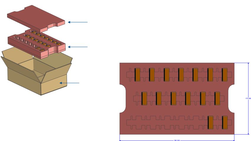
customized for an application’s needs and can be set to use one of various filter profiles
available within the Xsens sensor fusion engine. In this way, the MTi-600 limits the load
and the power consumption on the user application’s processor. The user can
communicate with the module by means of three different communication interfaces;
RS232, CAN and UART3. Other interfaces are available using an MTi Development Kit or
by using third party equipment (e.g. UART/RS232 to USB converter).

Contrary to the above image, the MTi-680G includes an internal RTK enabled GNSS
receiver. Which also provides PPS signals for synchronization purposes.

1.3 MTi 600-series product variants
The MTi-6x0 module is a fully tested self-contained module available as an:
    - Inertial Measurement Unit (IMU),
    - Vertical Reference Unit (VRU),
    - Attitude and Heading Reference System (AHRS)
    - GNSS aided Inertial Navigation System (GNSS/INS).

The MTI-680G is a fully tested self-contained rugged product with an integrated RTK
GNSS/INS receiver.

It can output 3D orientation data (Euler angles, rotation matrix or quaternions),
orientation and velocity increments (∆q and ∆v), position and velocity quantities and
calibrated sensor data (acceleration, rate of turn, magnetic field and pressure).
Depending on the product variant, output options may differ.

1.3.1 MTi-610 IMU
The MTi-610 module is an IMU that outputs calibrated 3D rate of turn, 3D acceleration,
3D magnetic field and barometric pressure. The MTi-610 also outputs coning and sculling
compensated orientation increments and velocity increments (∆q and ∆v). Advantages
over a simple gyroscope-accelerometer combo-sensor are the inclusion of synchronized
magnetic field and barometric data, on-board signal processing and the easy-to-use
synchronization and communication protocol. The signal processing pipeline and the suite
of output options allow access to the highest possible accuracy at any output data rate
up to 2000 Hz. Moreover, the testing and calibration is already performed by Xsens and
results in a robust and reliable sensor module, which enables a short time to market for
the users.

1.3.2 MTi-620 VRU
The MTi-620 is a 3D VRU. On top of the functionality of the MTi-610 IMU, its algorithm
computes 3D orientation data with respect to a gravity referenced frame: drift-free roll,
pitch and unreferenced yaw. Although the yaw is unreferenced, it is superior to only
gyroscope integration as a result of advanced on-board sensor fusion. The 3D
acceleration is also available as so-called free acceleration, which has the local-gravity
subtracted. The drift in unreferenced heading can be limited by using the Active Heading
Stabilization (AHS) functionality, see Table 17 for more details. The raw sensor signals

3   UART port is not available on MTi-680G

                                             10                          www.xsens.com
are combined and processed at a high frequency to produce a real-time data stream with
device’s 3D orientation (roll, pitch and yaw) up to 400 Hz.
1.3.3 MTi-630 AHRS
The MTi-630 supports all features of the MTi-610 and MTi-620, and in addition is a full
magnetometer-enhanced AHRS. In addition to the roll and pitch, it outputs a true
magnetic North referenced yaw (heading) and calibrated sensors data: 3D acceleration,
3D rate of turn, 3D orientation and velocity increments (∆q and ∆v) and 3D earth-
magnetic field data. The raw sensor signals are combined and processed at a high
frequency to produce a real-time data stream with device’s 3D orientation (roll, pitch and
yaw) up to 400 Hz.
1.3.4 MTi-670 GNSS/INS
The MTi-670 provides a GNSS/INS solution offering a position and velocity output in
addition to orientation estimates. The MTi-670 uses advanced sensor fusion algorithms
developed by Xsens to synchronize the inputs from the module’s on-board gyroscope,
accelerometer, magnetometer and barometer, with the data from an external GNSS
receiver. The raw sensor signals are combined and processed at a high frequency to
produce a real-time data stream with device’s 3D position, velocity and orientation (roll,
pitch and yaw) up to 400 Hz.
1.3.5 MTi-680G RTK GNSS/INS
The MTi-680G provides a GNSS/INS solution offering a cm-level accurate position and
velocity output (when correction signals are provided) in addition to orientation
estimates. The MTi-680G uses an internal L1/L2 RTK enabled GNSS receiver.
11 www.xsens.com2 Sensor specifications
This section presents the performance and the sensor component specifications for the
calibrated MTi-6x0 series products. Each product has passed the Xsens calibration
process individually. The Xsens calibration procedure calibrates for many parameters,
including bias (offset), alignment of the sensors with respect to the PCB and to each
other, and gain (scale factor). All calibration values are temperature dependent and
temperature calibrated. The calibration values are stored in the non-volatile memory of
the module.
In addition, some calibration parameters are continuously improved and/or re-estimated
through the on-board sensor fusion algorithms during normal operation of the product.
2.1 MTi 600-series performance specifications
Table 3: Orientation performance specifications
Parameter Condition MTi-610 MTi-620 MTi-630 MTi-670 MTi-680G
IMU VRU AHRS GNSS/INS RTK
GNSS/INS
Roll/Pitch Static N/A 0.2º 0.2º 0.2º 0.2º
Dynamic N/A 0.5º 0.5º 0.5º 0.5º
Yaw Dynamic N/A Unreferenc 1º 1º 1º
ed
Table 4: Position and velocity performance specifications for MTi-670-DK
Parameter Direction Specification
Position Horizontal 1.0 m
Vertical 2.0 m
Velocity 3D 0.05 m/s
Table 5: Position and velocity performance specifications for MTi-680G with RTK correction signals
provided
Parameter Direction Specification
Position Horizontal2.2 Sensor specifications
Table 6: MTi 600-series gyroscope specifications
Gyroscope specification4 Unit Value
Standard full range [°/s] ±2000
In-run bias stability [°/h] 8
Bandwidth (-3dB) [Hz] 520
Noise density [°/s/√Hz] 0.007
g-sensitivity [°/s/g] 0.001
(calibrated)
Non-linearity [%FS] 0.1
Scale Factor variation [%] 0.5 (typical)
1.5 (over life)
Table 7: MTi 600-series accelerometer specifications
Accelerometer4 Unit Value
Standard full range [g] ±10
In-run bias stability [mg] 0.01
Bandwidth (-3dB) [Hz] 500
Noise density [µg/√Hz] 60
Non-linearity [%FS] 0.1
Table 8: MTi 600-series magnetometer specifications
Magnetometer4 Unit Value
Standard full range [G] ±8
Non-linearity [%] 0.2
Total RMS noise [mG] 1
Resolution [mG] 0.25
Table 9: MTi 600-series barometer specifications
Barometer4 Unit Value
Full range [hPa] 300-1250
Total RMS Noise [Pa] 1.2
Relative accuracy [Pa] ±8 5
Table 10: MTi 600-series orthogonality specifications
Parameter4 Unit Value
Non- [°] 0.05
orthogonality
(accelerometer)
4 As Xsens continues to update the sensors on the module, these specifications are subject to
change.
5 Equivalent to 0.5 m.
13 www.xsens.comNon- [°] 0.05
orthogonality
(gyroscope)
Non- [°] 0.05
orthogonality
(magnetometer)
Table 11: MTi-680G GNSS specifications
GNSS Unit Value
Acquisition Cold start [s] 24 6
Hot start [s] 2
Convergence time RTK [s] < 10 7
Horizontal pos. accuracy PVT [m] 1.5
RTK8 [m] 0.01
Vertical pos. accuracy RTK8 [m] 0.01
Supported GNSS signals:
GPS L1C/A [MHz] 1575.42
L2C [MHz] 1227.60
GLONASS L1OF [MHz] 1598.0 - 1605.4
L2OF [MHz] 1242.9 – 1248.6
Galileo E1-B/C [MHz] 1575.42
E5b [MHz] 1207.14
BeiDou B1l [MHz] 1561.098
B2l [MHz] 1207.14
6 Using GPS + GLONASS + Galileo + BeiDou.
7 < 30 s for GPS only.
8 Measured using 1 km baseline and patch antennas with good ground planes. Does not account for
possible antenna phase center offset errors.
14 www.xsens.com3 Functional description
This chapter describes the MTi-600 pinout and gives details about the supported
communication interfaces.
3.1 Pin description module
The pin map shows the peripheral interfaces.
Figure 2: Pin configuration of the MTi 600-series module (bottom view)
Table 12: Pin descriptions of the MTi-600
Pin Name I/O type Description
1 VIN PWR Power input
2 GND PWR Ground
3 CAN_H I/O CAN bus differential high side
4 CAN_L I/O CAN bus differential low side
5 RS232_TxD O RS232 transmitter output to host
6 RS232_RTS O RS232 Ready To Send output to host
7 RS232_RxD I RS232 receiver input from host
8 RS232_CTS I RS232 Clear To Send input from host
9 SYNC_IN1 I Multifunctional synchronization input
10 SYNC_IN2 I Multifunctional synchronization input
11 GNSS_TxD9 O RS232 transmitter output to GNSS module
12 GNSS_RxD9 I RS232 receiver input from GNSS module
13 SYNC_OUT O Configurable synchronization output
14 GND PWR Ground
15 UART_TxD O UART transmitter output
16 UART_RxD I UART receiver input
9 Only available for MTi-670. Do not connect for other models.
15 www.xsens.com3.2 Pin description MTi-680G
Figure 3 show the three connectors on the rugged housing
Figure 3 Connectors and pin numbers on the MTi-680G housing
Table 13 shows the pin descriptions of the MTi-680G Host Interface connector.
Table 13: Pin descriptions MTi-680G Host Interface
Pin Name I/O type Description
1 CAN_H I/O CAN bus differential high side
2 CAN_L I/O CAN bus differential low side
3 SYNC_IN1 I Multifunctional synchronization input
4 SYNC_IN2 I Multifunctional synchronization input
5 VIN PWR Power input
6 RS232_CTS I RS232 Clear To Send input from host
7 RS232_RxD I RS232 receiver input from host
8 RS232_TxD O RS232 transmitter output to host
9 RS232_RTS O RS232 Ready To Send output to host
10 GND PWR Ground
11 SYNC_OUT O Configurable synchronization output
12 GND PWR Ground
Table 14 shows the pin descriptions of the MTi-680G RTCM corrections connector.
Table 14: Pin descriptions MTi-680G RTCM corrections
Pin Name I/O type Description
1 V_BCKP PWR Backup supply for GNSS (3V3).
2 GND PWR Ground
3 RTCM_RxD I RS232 receiver input from host
4 RTCM_TxD O RS232 transmitter output to host
16 www.xsens.com3.3 Peripheral interfaces
The MTi 600-series module supports CAN, RS232, and UART interfaces for host
communication. For more detailed information on the interfaces please refer to the MTi
600-series Hardware Integration Manual10.
3.3.1 CAN (Controller Area Network)
A Controller Area Network (CAN bus) is a robust standard designed to allow
communication between devices in applications without a host computer. The CAN
interface of the MTi-600 does not include a termination resistor. It can be used in a CAN
bus that already incorporates the required termination. If used in a single device
connection, a 120 Ω termination resistor needs to be added between the CAN_H and
CAN_L pins.
3.3.2 RS232 with RTS/CTS flow control
The RS232 interface complies with the standard RS232 voltage levels. It includes
hardware flow control through RTS and CTS lines.
3.3.3 UART
The UART interface can be used to directly connect to an MCU with 3.3 V IO-levels. The
user can configure the MTi 600-series module to communicate over UART. The UART
frame configuration is 8 data bits, no parity and 1 stop bit (8N1). The UART protocol only
has the TX and RX lines without any flow control.
Due to the rugged build, the UART port is not available on MTi-680G devices.
3.3.4 RTCM input port
The RTCM input port on the MTi-680G can be used to provide RTCM correction messages.
The port uses RS232 signalling with 8 data bits, no parity and 1 stop bit. The default
baud rate on this port is 38400 bit/s, but a higher baud rate can be configured. Refer to
Table 15 for available baud rates, and the low-level communication document for details
on the SetPortConfig command to configure it.
Table 15 RTCM input port baud rates
baud rate [bit/s]
38k4 (default)
57k6
115k2
230k4
460k8
921k6
10Links to the latest available documentation can be found via the following link: Xsens MTi
Documentation
17 www.xsens.com4 Signal processing and algorithms
This section discusses the MTi-600 series signal processing and algorithm description.
4.1 Signal processing pipeline
The MTi 600-series is a self-contained product, all calculations and processes such as
sampling, coning & sculling compensation and the Xsens sensor fusion algorithm run on
board.
4.1.1 Strapdown integration
The Xsens optimized strapdown algorithm performs high-rate dead-reckoning
calculations up to 2000 Hz allowing accurate capture of high frequency motions. This
approach ensures a high bandwidth. Orientation and velocity increments are calculated
with full coning & sculling compensation. These orientation and velocity increments are
suitable for any 3D motion tracking algorithm. Increments are internally time-
synchronized with other sensors. The output data rate can be configured for different
frequencies, see Table 19. The inherent design of the signal pipeline with the
computation of orientation and velocity increments ensures there is absolutely no loss of
information at any output data rate. This makes the MTi 600-series attractive also for
systems with limited communication bandwidth.
4.1.2 Xsens sensor fusion algorithm for VRU and AHRS product types
MTi-620 and MTi-630 run the newest Xsens sensor fusion algorithm implementing the
latest Xsens insights. It optimally estimates the orientation with respect to an Earth fixed
frame utilizing the 3D inertial sensor data (orientation and velocity increments) and 3D
magnetometer data.
The Xsens sensor fusion algorithm uses assumptions to obtain the orientation
estimations. Since the assumptions may be more or less valid based on the
characteristics of the typical dynamics of the application, and since the magnetic field
differs per application, the Xsens algorithm makes use of a set of filter profiles to be able
to use the correct assumptions given the application. This way, the algorithm can be
optimized for different types of movements and conditions.
With the MTi-620 and MTi-630, the user can configure different algorithm behaviours by
selecting a “base” filter profile and, next to it, a heading behaviour (see Figure 4).
The “base” filter profile selection affects the general behaviour of the device, mainly
based on the nature of the typical expected dynamics of the application. The heading
behaviour, as the name suggests, affects the heading/yaw output of the MTi, and
determines how the magnetometer measurements are interpreted. This tiered approach
gives more freedom to select the desired behaviour for different user application
scenarios. Table 16 and Table 17 summarize the filter profile and heading behaviour
options.
18 www.xsens.comEvery application is different and results may vary from setup to setup. It is
recommended to reprocess recorded data with different filter profiles in MT Manager 11 to
determine the best filter profile for your specific application.
Table 16: Filter profiles for MTi-620 and MTi-630
Name Product Description Typical applications
Responsive MTi-620 This filter profile is designed for indoor • Outdoor/Indoor
MTi-630 applications as well as applications that handling objects
experience high dynamics and jerky • Indoor ground
movements. When the MTi is static, an vehicles
automatic gyro bias estimation is performed • Outdoor/Indoor head
in the background. tracker
• Indoor mapping,
outdoor mapping if
handheld (e.g. tripods
with camera,
backpack)
• Industrial robotic arm
Robust MTi-620 This filter profile is suitable for most of the • Ships/vessels
MTi-630 applications. Compared to the other filter • Automotive
profiles it has a more robust tuning. When • Ground vehicles
the MTi is static, an automatic gyro bias outdoor
estimation is performed in the background. • Outdoor mapping with
vehicles
General12 MTi-620 This filter profile behaves like the General • Automotive
MTi-630 filter profile implemented for the previous • Ground vehicles
generation Xsens Products (e.g. MTi-30). It outdoor
is more sensitive to the magnetic field • Outdoor mapping with
changes. It does not perform an automatic vehicles
gyro bias estimation in background. This
filter profile cannot be combined with the
FixedMagRef heading behaviour.
11Recording a data file to be reprocessed in MT Manager
12The General filter profile is only recommended for users who are looking forsimilar behaviour as
the previous generation Xsens products in the typical applications suggested in the table. Using the
General filter profile is not recommended for new designed applications.
19 www.xsens.comTable 17: Heading Behaviour
Name Product Description Typical applications
NorthReference MTi-630 This heading behaviour assumes a All applications that
homogeneous magnetic environment that require a North
can be used to estimate a stable North referenced heading
referenced heading. and are used in a
homogeneous
magnetic field.
FixedMagRef MTi-630 This heading behaviour is based on the All applications that
idea that the heading is not necessarily are used in
referenced to the local magnetic North. environments where
Instead, it maintains a fixed heading different magnetic
reference frame based on what is defined fields are present
when the MTi is powered up (based on the (e.g. mixed
initially observed magnetic field). This indoor/outdoor
means that there is no drift with respect applications).
to the starting frame when the local
magnetic field changes. For example,
when moving from room A to room B,
where room B has a different local
magnetic field direction than room A, the
heading output of the MTi does not
change. This is in contrast to the
NorthReference heading behaviour, which
forces the MTi to estimate the heading
based on the local magnetic field.
VRU MTi-620 The yaw is unreferenced. This means that Applications where
MTi-630 it is initialized at 0° when the MTi is only roll and pitch is
powered up and the yaw will be computed of interest and/or
relative to this initial orientation. The applications that are
magnetic field is not used to estimate the used in environments
yaw. Because of small inaccuracies that where the magnetic
originate when integrating gyroscope field cannot be trusted
data, the Yaw output will contain an error (e.g. stabilized
that builds up over time, also known as antenna platforms or
“drift”. Note however, that because of the pipeline inspection
working principle of the sensor fusion tools).
algorithm, the drift in yaw will be much
lower than when gyroscope signals would
be simply integrated.
VRUAHS MTi-620 This heading behaviour activates the Scenarios where the
MTi-630 Active Heading Stabilization (AHS) on top magnetic field cannot
of the above described VRU behaviour. be trusted completely,
AHS is a software component within the but a stable yaw is
sensor fusion engine designed to give a needed.
low-drift unreferenced heading solution,
even in a disturbed magnetic
environment. The yaw remains
unreferenced, but the drift is limited13.
13For more information on the capabilities of AHS, refer to the BASE article: AHS. Note that in the
previous Xsens products, AHS was activated by means of a separate setting.
20 www.xsens.comFigure 4: Filter profile and heading behaviour selection: a tiered approach
21 www.xsens.com4.1.3 Xsens sensor fusion algorithm for the GNSS/INS product type
The Xsens sensor fusion algorithm in the GNSS/INS products has several advanced
features. The algorithm adds robustness to the orientation and position estimates by
combining measurements and estimates from the inertial sensors, magnetometer,
barometer and a GNSS receiver in order to compensate for transient accelerations and
magnetic disturbances.
The GNSS status is continuously monitored and the filter accepts GNSS data when
available and sufficiently trustworthy. When the product has limited/mediocre GNSS
reception or even no GNSS reception at all (e.g. during outages), the fusion algorithm
seamlessly adjusts the filter settings in such a way that the highest possible accuracy
output is maintained. The MTi will continue to output position, velocity and orientation
estimates, although the accuracy is likely to degrade over time as the filters can only rely
on dead-reckoning. If the GNSS outage lasts longer than 45 seconds, the MTi stops the
output of the position and velocity estimates, and resumes sending these outputs once
the GNSS data becomes acceptable again.
Smoothers
The GNSS/INS products (MTi-670 and MTi-680G) have optional sensor fusion functions
called smoothers for reducing sudden jumps in the output data that may arise from
fusing low-rate GNSS receiver messages with high-rate inertial sensor data. There is a
smoother for orientation data for both the MTi-670 and MTi-680G, and a position/velocity
smoother for the MTi-680G. The smoothers can be enabled from the Device Settings
window in MT Manager, or by using the setOptionFlags low-level communication
command (see [LLCP] for details).
Lever Arm Correction
Due to the improvement in position accuracy on MTi-680G devices with RTK support, the
option to configure a GNSS lever arm is available. Figure 5 highlights the effect of the
lever-arm on measurements taken with cm level accuracy.
The lever-arm describes the position of the GPS antenna with respect to the origin of
measurement of the MT device (see page 36). The algorithm uses this information to
correct its position and velocity measurements accordingly. The lever-arm can be set
from the Device Settings window in MT-Manager, or by using the setGnssLeverArm low-
level communication command (see [LLCP] for details).
22 www.xsens.comFigure 5: Lever arm correction for MTi-680G
Filter profiles
Table 18 reports the different filter profiles the user can set based on the application
scenario. Every application is different and results may vary from setup to setup. It is
recommended to reprocess recorded data with different filter profiles in MT Manager 14 to
determine the best results in your specific application.
Table 18: Filter profiles for MTi-670 and MTi-680G (GNSS/INS)
Name GNSS15 Barometer Magnetometer Description
General / This filter profile is the default
General_RTK • • setting. The yaw output of the MTi
is North referenced (when GNSS
data is available). Altitude
(height) is determined by
combining static pressure, GNSS
altitude and accelerometers. The
barometric baseline is referenced
by GNSS, so during GNSS
outages, accuracy of height
measurements is maintained.
14 Recording a data file to be reprocessed in MT Manager
15 External GNSS receiver (position aiding sensor) for the MTi-670
23 www.xsens.com•
GeneralNoBaro / This filter profile is very similar to
GeneralNoBaro_RTK the general filter profile except for
the use of the barometer.
GeneralMag / This filter profile bases its yaw
GeneralMag_RTK • • • estimate mainly on magnetic
heading and GNSS
measurements. A homogenous
magnetic environment and a
proper magnetic calibration are
essential for a good performance.
This filter profile produces a North
referenced yaw output directly
after powering up the MTi.
Real-Time Kinematics
The MTi-680G supports centimetre level position accuracy through RTK (Real-Time
Kinematic) positioning, which uses correction messages from a base station with a known
position. The RTK correction data must be supplied as RTCM3 messages, either via the
dedicated RTCM input connector (see Figure 3) or via the host interface as RTCM
messages embedded in xbus (see XMID_ForwardGnssData in the low-level
communication documentation). In the later case, the NTRIP client in MT-Manager can be
setup to provide the correction data.
4.2 Data output
The MTi 600-series product variants can output many different data types at many
different frequencies. Below is a summary of the most relevant data and maximum
output data rates. A full overview is available in the MT Low Level Communication
Protocol Documentation16.
Table 19: Output data rates
Data Type Max Output Data Rate
Orientation data (Euler angles, Rotation Matrix, 400Hz
Quaternions)
Position, Velocity, Altitude 400Hz
DeltaQ, DeltaV 400Hz
Acceleration, Rate of Turn, Free Acceleration 400Hz
Acceleration HR (High Rate) 2000Hz
Rate of Turn HR (High Rate) 1600Hz
4.2.1 Xbus output
The Xbus protocol is Xsens’ standard output protocol utilizing the MTDATA2 data
message structure. This output provides a lot of flexibility and enables users to access all
16Links to the latest available documentation can be found via the following link: Xsens MTi
Documentation
24 www.xsens.comfunctionality of the MTi product range. The Xbus output format is shared with all other
MTi products in the Xsens portfolio, so switching between hardware platforms is very
easy. More information is available in the MT Low Level Communication Protocol
Documentation8.
4.2.2 NMEA output
NMEA output is a string output mode which outputs data in the commonly used NMEA
0183 format. More information is available in the MT Low Level Communication Protocol
Documentation8.
4.2.3 CAN output
The CAN output is an industrial standard interface over which the MTi 600-series can
output its data. More information on this output can be found in the MT Low Level
Communication Protocol Documentation8 and Family Reference Manual8.
4.3 GNSS input
The MTi-670 requires GNSS receiver data to provide a full GNSS/INS solution. This can
be achieved by using the UBX protocol (uBlox proprietary protocol) or with NMEA input.
When connecting a uBlox receiver (e.g. uBlox MAX-M8), the MTi will configure it correctly
on start-up. No prior configuration of the uBlox receiver is required. It is however
recommended to inform the MTi of what type of uBlox receiver is connected. An Xbus
message called SetGnssReceiverSettings, described in the MT Low Level Communication
Protocol Documentation, can be used to select one of the officially supported uBlox receiver
series: MAX-M8 (default), NEO-M8 or ZED-F9.
Alternatively, NMEA input or simply NMEAin is a functionality that allows the input of data
from an external GNSS receiver using the NMEA protocol. As almost all GNSS receivers
support the output of NMEA messages, this functionality enables the use of virtually any
GNSS receiver.
It is important to note that both the GNSS receiver and the MTi must be configured prior
to connecting both systems to each other. The NMEAin for the MTi-670 can be enabled
through the SetGnssReceiverSettings Xbus message, described in the MT Low Level
Communication Protocol Documentation.
Table 20 summarizes the settings needed to configure the MTi-670 to use the NMEAin
option. This will enable the MTi-670 to use the GNSS data and provide the user with a full
GNSS/INS solution. The MTi-670 will also sync its internal clock to the UTC time that is
present in the sentences.
Table 20: Settings required to enable NMEAin for the MTi-670
Setting Description
Baudrate Minimum 115200 bps
GNSS Message frequency 4 Hz
Talker ID GN, GP or GL
Required messages GGA, GSA, GST and RMC
25 www.xsens.comHigh precision coordinate formats such as GGALONG are also
supported
4.4 Magnetic interference
Magnetic interference can be a major source of error for the heading accuracy of any
AHRS, as an AHRS uses the magnetic field to reference the estimated orientation on the
horizontal plane with respect to the (magnetic) North. A severe and prolonged distortion
in that magnetic field will cause the magnetic reference to be inaccurate. The MTi 600-
series has several ways to cope with these distortions to minimize the effect on the
estimated orientation, which are discussed in the sections below.
4.4.1 Magnetic Field Mapping (MFM)
When the distortion moves with the MTi (i.e. when a ferromagnetic object solidly moves
with the MTi module), the MTi can be calibrated for this distortion. Examples are the
cases where the MTi is attached to a car, aircraft, ship or other platforms that can distort
the magnetic field. It also handles situations in which the sensor has become
magnetized. These type of errors are usually referred to as soft and hard iron distortions.
The Magnetic Field Mapping procedure compensates for both hard iron and soft iron
distortions.
The magnetic field mapping (calibration) is performed by moving the MTi mounted on the
object/platform that is causing the distortion. The results are processed on an external
computer (Windows or Linux), and the updated magnetic field calibration values are
written to the non-volatile memory of the MTi 600-series. The magnetic field mapping
procedure is extensively documented in the Magnetic Calibration Manual17.
4.5 Frames of reference
The MTi 600-series uses a right-handed coordinate system. The default sensor-fixed
frame (Sxyz) is defined as shown in Figure 6 (module) and Figure 7 (MTi-680G)Error!
Reference source not found.. The frame is also printed on the side of the module
(back side of MTi-680G). For a more exact location of the sensor frame origin, refer to
Section 7.1. When the sensor is rigidly attached to another object or vehicle, it is
possible to rotate the sensor-fixed frame Sxyz to an object coordinate frame (Oxyz)18. The
default local earth-fixed frame (LXYZ) is East-North-Up (ENU). In addition, the MTi-6x0
has predefined output options for North-East-Down (NED) and North-West-Up (NWU).
For specifically the MTi-670, the Local Tangent Plane (LTP) is a local linearization of the
Ellipsoidal Coordinates (Latitude, Longitude, Altitude) in the WGS-84 Ellipsoid, based on
the real time position data retrieved from the GNSS receiver. Since the MTi-620 and MTi-
630 cannot receive real time positioning from a GNSS receiver, the user must set correct
positional coordinates to allow the MTi-620 or MTi-630 to construct the reference frame,
magnetic and gravity models.
17 Links to the latest available documentation can be found via the following link: Xsens MTi
Documentation
18 How to define a new object coordinate system can be found in the MTi Family Reference Manual
26 www.xsens.comFigure 6 Default sensor fixed coordinate system (Sxyz) for the MTi 600-series module
Figure 7: Default sensor coordinate system for the MTi-680G
27 www.xsens.com5 Synchronization options
This chapter describes the synchronization functionalities of the MTi-600 series. In the
remainder of this chapter, synchronization will be abbreviated as sync, synchronization
input as SyncIn and synchronization output as SyncOut. A set of one or more
synchronization options and their corresponding parameters are stored in a structure
referred to as SyncSettings.
The sync functionalities are in line with the other Xsens motion trackers, however, some
minor differences exist because of the different architecture of the MTi-600.
The MTi-600 series has two input lines available for SyncIn, and one for SyncOut (see
Table 12). It is not possible to configure a SyncIn line as SyncOut or vice versa.
On devices which employ an external GNSS receiver, a 1PPS signal can be gathered
directly form the GNSS receiver. However, it is also possible to configure a 1 Hz output
reference signal using the SyncOut functionalities. The output reference signal is
synchronized with the 1PPS signal of the external GNSS receiver when using an MTi-670,
or the internal GNSS receiver when using an MTi-680G.
5.1 Trigger signal
A trigger signal is expected to be a pulse wave (See Table 27 for the trigger signal
requirements). When using a SyncIn function the trigger is an input signal. When using a
SyncOut function it is a output signal generated by the MTi. When configuring a sync
function, various parameters can be set by the user to interpret/generate the trigger
signal. This parameters are reported in Table 21.
Table 21: Generic synchronization parameters
Parameter Description
Line Defines the physical line to be used for the sync function.
Valid values:
• In1
• In2
• ReqData
• Out1
All SyncIn functions can be employed on both input lines. If a function has to be
enabled on both SyncIn lines, the functions must be included twice in the
configuration settings, i.e. once for each line. ReqData is specifically used for the
Send Latest function.
Polarity Valid values:
• Rising edge: the trigger is sensitive to the rising edge of the pulse wave
• Falling edge: the trigger is sensitive to the falling edge of the pulse wave
• Falling & Rising edge: the trigger is sensitive to both edges
SkipFirst Ignore the first “n” input triggers.
SkipFactor Periodically skips every n input triggers. This skipping starts after the “n” SkipFirst
pulses.
Trigger If the Once option is set, the sync function is only triggered once and the following
Once pulses are ignored. The Once feature is considered only after the SkipFirst count is
reached. Its state is reset when the MTi enters a new Measurement mode.
28 www.xsens.comPulse Pulse duration in microseconds.
width
Delay Delay in microseconds to react at the trigger event.
5.2 SyncIn
This chapter describes the functionality and behaviour of the SyncIn line. The SyncIn
lines can be used to synchronize the sampling of data or data output of the MTi 600-
series to an external device or clock by inputting a trigger signal through the SyncIn
lines. See Table 27 for the trigger signal requirements.
5.2.1 TriggerIndication function
With this function the user can input a trigger signal to mark the output data (e.g.
orientation) with the trigger event. Upon receiving a trigger, this function will set the
trigger indication status bit (SyncIn Marker) of the Status Word to 1. Furthermore, the
user can configure the MTi to output also a TriggerIndication message through the
MtData2 stream. The advantage is that this message is timestamped with the trigger
moment, so it has better accuracy than just the status flag.
5.2.2 SendLatest function
Enabling this function, the last measured/computed desired data available at the trigger
instant is outputted by the MTi. The internal signal pipeline of the MTi works as usual, but
the desired data is outputted only when a trigger is received.
The trigger can be sent either on a SyncIn line or by means of a software command (Line
must be set to ReqData).
5.2.3 StartSampling function
When this function is enabled, the device will start outputting data after a SyncIn trigger
has been received. It does not trigger every consequent sample, but it accurately starts
outputting the first sample, after which the next samples will follow the selected output
data rate. A skipFirst value can be set to ignore the first n pulses before considering a
pulse as a trigger.
Similarly, a delay parameter can be set to tune when to start the sampling after the
trigger.
5.2.4 Clock Bias Estimation function
This function enables the user to synchronize the sampling clock of the MTi with an
external reference signal. The internal clock of the MTi-600 has an accuracy of about 10
ppm. When a reference clock of better accuracy is available, it is possible to use this
clock to improve the sampling accuracy of the MTi-600. Furthermore, it could be
beneficial to have all devices in a setup to run at the same clock speed.
If the user does not have a reference clock that is better than 10 ppm, but it is still
preferred to run multiple devices at the same clock speed, it is better to use the SyncOut
line of the MTi-600 as a clock source for other devices.
29 www.xsens.comOn the MTi-680G the internal clock is always referenced to the internal GNSS receiver.
Therefore, on the MTi-680G the clock bias estimation is not user configurable.
5.2.5 1PPS Time-pulse function
When an MTi-670 is connected with an external GNSS receiver, the 1PPS signal of the
receiver can be used as input to synchronize the MTi-670 with the external receiver. Not
available on MTi-610/MTi-620/MTi-630. On the MTi-680G this function is always enabled
with the time pulse from the internal GNSS receiver.
30 www.xsens.com5.3 SyncOut
The MTi 600-series has one output synchronization function.
5.3.1 Interval Transition Measurement function
The Interval Transition Measurement function gives a sampling time indication letting the
user to synchronize external applications with the same clock employed by the MTi-600
to output the data. It generates a SyncOut trigger based on the internal 400 Hz SDI
sampling clock.
5.4 Combining multiple Sync functions
The following list of possible sync functions are available:
• ClockSync [in]
• TriggerIndication [in]
• SendLatest [in]
• StartSampling [in]
• Interval Transition Measurement [out]
Table 22: Remarks on combining multiple Sync functions
Function Description
ClockSync If ClockSync is configured on a SyncIn line, no other function can be
configured on this line at the same time.
TriggerIndication Is a somewhat passive function in the sense that it does not change
the state or timing of the system. It can therefore be freely
combined with all other functions. It can also be configured on both
SyncIn lines with different settings.
SendLatest/StartSampling Only one of these functions can be active and only on one line.
SamplingIndication Can be configured next to all possible SyncIn functions.
31 www.xsens.com6 System and electrical specifications
6.1 Interface specifications
Table 23: Communication interfaces
Interface Symbol Min Typ Max Unit Description
CAN fCAN 10.0 250.0 1000 kbps Host CAN Interface Baud Rate
RS232 fRS232 4.8 115.2 1000 kbps Host RS232 Interface Baud Rate
UART19 fUART 4.8 115.2 2000 kbps Host UART Interface Baud Rate
6.2 System specifications
Table 24: System specifications of MTi 600-series modules
Min Typ Max Unit Comments
Size Width 31.5 mm
Length 28.0 mm
Height 13.0 mm
Weight 8.9 gram
Temperature Operating -40 +85 ºC Ambient temperature, non-
temperature condensing
Power 310 340 530 mW Depends on used interface and
consumption supplied voltage. 5V over UART is
most power efficient
Timing 10 ppm Output clock accuracy of 1 ppm
accuracy can be achieved with the MTi-670
with external GNSS module
MTBF GM 40.000 hours
MTBF GB 360.000 hours
Output data 400 2000 Hz Data rates larger than 400 Hz
rate available for RateOfTurnHR (1600
Hz) and AccelerationHR (2000
Hz) only
Table 25: System specifications of MTi-680G
Min Typ Max Unit Comments
Size Width 40.9 mm
Length 56.5 mm 58.1 mm including SMA connector
Height 36.8 mm
Weight 98 gram
IP-rating IP68 48 hours at 1 meter under water
Temperature Operating -40 +85 ºC Ambient temperature, non-
temperature condensing
Power 620 720 1000 mW Depends on used interface and
consumption supplied voltage.
19 Not available on MTi-680G.
32 www.xsens.comTiming 1 ppm
accuracy
Output data 400 2000 Hz Data rates larger than 400 Hz
rate available for RateOfTurnHR (1600
Hz) and AccelerationHR (2000 Hz)
only
33 www.xsens.com6.3 Electrical specifications
Table 26: Supply voltage specifications
Symbol Min Typ Max Unit Description
VIN 4.5 5 24 V Power input voltage
VBCKP20 1.7 3.0 3.6 V GNSS backup input voltage
Table 27: I/O electrical specifications
I/O interface Symbol Min Typ Max Unit Description
CAN VI(DIFF)(R) -4.0 0.5 V Recessive differential input voltage
-12V < V(CANH, CANL) < +12V
VI(DIFF)(D) 0.9 9.0 V Dominant differential input voltage
-12V < V(CANH, CANL) < +12V
VO(DIFF)(R) -500 0 50 mV Recessive differential output voltage
VO(DIFF)(D) 1.3 2.0 5.0 V Dominant differential output voltage
VO(L)(D) 0.5 1.5 2.25 V CAN_L dominant output voltage
VO(H)(D) 2.75 3.5 4.5 V CAN_H dominant output voltage
RS23221 VIL -25 0.6 V Low input voltage
(GNSS/RTCM) VIH 2.4 +25 V High input voltage
VOT ±5 ±5.4 V Driver Output Voltage swing
UART22 VIL 0 0.88 V Low input voltage
VIH 2.29 3.6 V High input voltage
VOL 0 0.44 V Low output voltage
VOH 2.6 3.3 V High output voltage
SYNC_IN1/ VIL -25 0.6 V Low input voltage
SYNC_IN2 VIH 2.4 +25 V High input voltage
SYNC_OUT VOL 0 0.44 V Low output voltage
VOH 2.6 3.3 V High output voltage
IO ±4 mA Output current
20 Only available on MTi-680G.
21 Also applies to the GNSS (MTi-670) and RTCM (MTi-680G) ports.
22 Not available on MTi-680G.
34 www.xsens.comYou can also read