User Manual - PCE Instruments
←
→
Page content transcription
If your browser does not render page correctly, please read the page content below
User Manual                                        English

     Weather Station PCE-FWS 20N

     User manuals in various languages (français,
italiano, español, português, nederlands, türk, polski,
       русский, 中文) can be found by using our
     product search on: www.pce-instruments.com

              Last change: 8 April 2020
                        v1.0

                 © PCE Instruments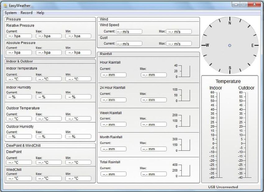
Contents
1       Safety notes ........................................................................................... 1
2       Glossary of common terms ................................................................. 2
3       Delivery contents .................................................................................. 2
4       Technical specifications ...................................................................... 3
5       LCD description .................................................................................... 4
6       Getting started ....................................................................................... 5
6.1     Before first use ................................................................................................................. 5
6.2     Setting up the display and outdoor unit ............................................................................. 5
6.3     Sensors............................................................................................................................ 6
6.4     Install U-bolts and metal plate .......................................................................................... 7
6.5     Install wind speed cups .................................................................................................... 8
6.6     Install wind vane............................................................................................................... 8
6.7     Install batteries ................................................................................................................. 9
6.8     Mount outdoor sensor .....................................................................................................10
6.9     Reset button and outdoor unit LED .................................................................................11
6.10 Basic operation ...............................................................................................................11
6.11 Best practices for wireless communication ......................................................................12

7       Operation ............................................................................................. 12
7.1     Indoor temperature ..........................................................................................................13
7.2     Outdoor temperature .......................................................................................................14
7.3     Indoor humidity................................................................................................................15
7.4     Outdoor humidity .............................................................................................................15
7.5     Wind speed .....................................................................................................................16
7.6     Rain ................................................................................................................................17
7.7     Weather forecast .............................................................................................................18
7.8     Pressure .........................................................................................................................19
7.9     Pressure bar graph .........................................................................................................20
7.10 Time ................................................................................................................................20
7.11 Date ................................................................................................................................20
7.12 Memory ...........................................................................................................................21

                                                       © PCE Instruments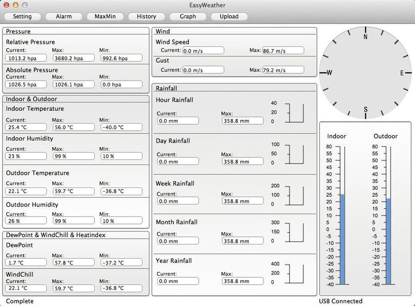
8       Maintenance ........................................................................................ 21
9       PC connection ..................................................................................... 21
9.1     Data storage ...................................................................................................................21
9.2     Data recall .......................................................................................................................21
9.3     Connections and software ...............................................................................................22
9.4     PC software installation ...................................................................................................22

10      Software ............................................................................................... 23
10.1 System Requirements .....................................................................................................23
10.2 Installation of the “EasyWeather” software ......................................................................23
10.3 Basic settings of the PC software ....................................................................................24
10.4 System menu ..................................................................................................................24
10.5 Save................................................................................................................................28
10.6 Troubleshooting: Graphs are not displayed .....................................................................30
10.7 Data upload.....................................................................................................................31
10.8 Help option ......................................................................................................................34

11      Software on MAC OS .......................................................................... 35
11.1 Installation of the “EasyWeather” software ......................................................................35
11.2 Basic settings ..................................................................................................................36
11.3 Alarm settings .................................................................................................................36
11.4 Max/Min display ..............................................................................................................37
11.5 Save................................................................................................................................37
11.6 Graphical view.................................................................................................................38
11.7 Data upload.....................................................................................................................38
11.8 Check software version ...................................................................................................39
11.9 Special notes about time synchronization between PC/MAC and display ........................39

12      Warranty ............................................................................................... 40
13      Disposal ............................................................................................... 40

                                                       © PCE Instruments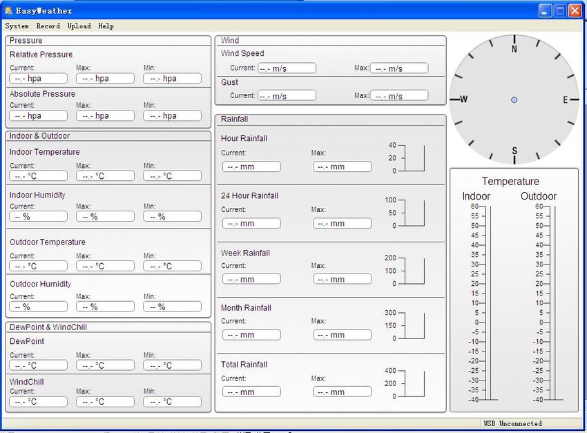
1     Safety notes
Please read this manual carefully and completely before you use the device for the first time. The
device may only be used by qualified personnel and repaired by PCE Instruments personnel.
Damage or injuries caused by non-observance of the manual are excluded from our liability and
not covered by our warranty.

     •    The device must only be used as described in this instruction manual. If used otherwise,
          this can cause dangerous situations for the user and damage to the meter.
     •    The instrument may only be used if the environmental conditions (temperature, relative
          humidity, …) are within the ranges stated in the technical specifications. Do not expose
          the device to extreme temperatures, direct sunlight, extreme humidity or moisture.
     •    Do not expose the device to shocks or strong vibrations.
     •    The case should only be opened by qualified PCE Instruments personnel.
     •    Never use the instrument when your hands are wet.
     •    You must not make any technical changes to the device.
     •    The appliance should only be cleaned with a damp cloth. Use only pH-neutral cleaner,
          no abrasives or solvents.
     •    The device must only be used with accessories from PCE Instruments or equivalent.
     •    Before each use, inspect the case for visible damage. If any damage is visible, do not
          use the device.
     •    Do not use the instrument in explosive atmospheres.
     •    The measurement range as stated in the specifications must not be exceeded under
          any circumstances.
     •    Non-observance of the safety notes can cause damage to the device and injuries to
          the user.

We do not assume liability for printing errors or any other mistakes in this manual.

We expressly point to our general guarantee terms which can be found in our general terms of
business.

If you have any questions please contact PCE Instruments. The contact details can be found at
the end of this manual.

                                       © PCE Instruments
                                              1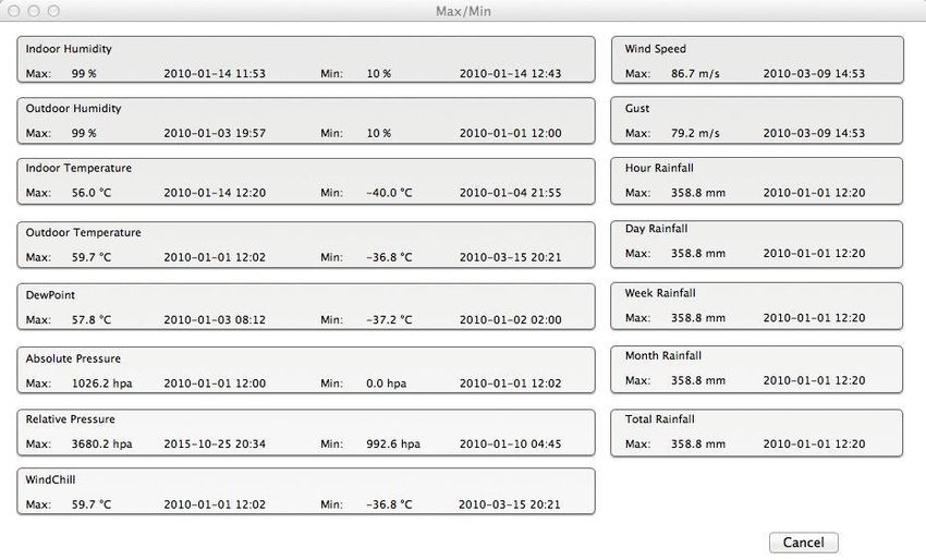
2     Glossary of common terms
DCF/WWVB
The DCF or WWVB time signal is an AM modulated time-of-day signal broadcasted by the Federal
Government of Germany, NIST from USA or National Physical Laboratory. The time base is
generated from an atomic time generator which is accurate to 10 billion of one second.

LCD
“LCD” is an acronym for ”Liquid Crystal Display”. This is a common type of display screen used
in televisions, computers, watches, and digital clocks.
BAROMETER & BAROMETRIC PRESSURE
A barometer is a device that measures the pressure of the air pushing on it—this measurement
is called the barometric pressure. We do not actually feel the barometric pressure because the
air pressure is pushing equally in every direction.
RELATIVE AIR PRESSURE
Relative air pressure is the same as the barometric pressure. The calculation of relative air
pressure is a combination of the absolute air pressure and the altitude.
ABSOLUTE AIR PRESSURE
Absolute air pressure is the actual air pressure on the barometer without regard to altitude.
INCHES OF MERCURY (inHg)
An inch of mercury is the common unit of measurement for air pressure in the United States.
HECTOPASCALS (hPa)
Hectopascals are the common unit of measurement for air pressure in the International System
(SI) of measurement. The hectopascal holds the same value as mbar.

3     Delivery contents
1 x display (receiver)
1 x solar panel
1 x wind direction sensor
1 x wind speed sensor
1 x rain gauge
1 x thermo-hygro sensor
1 x USB cable

The software for the weather station PCE-FWS 20N can be downloaded here:
https://www.pce-instruments.com/english/download-win_4.htm

                                       © PCE Instruments
                                              2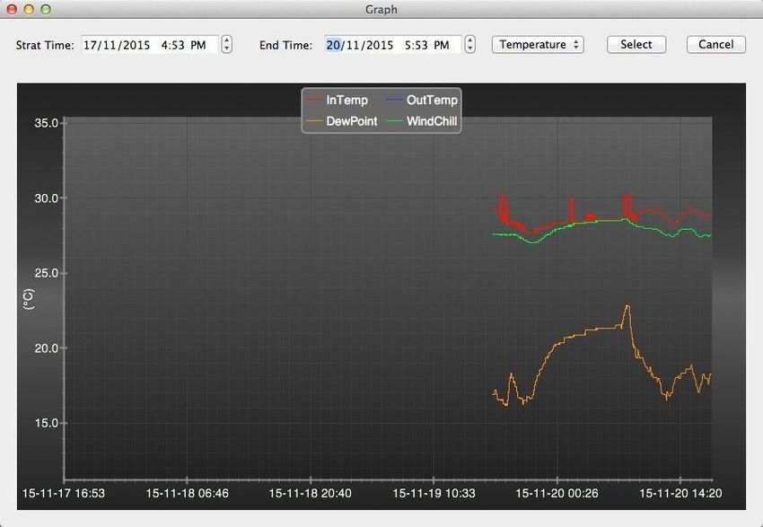
4       Technical specifications
Outdoor data
 Transmission distance in open field              100 m (300 feet)
 Frequency                                        868 MHz
 Temperature range                                -40 … 60 °C (-40 … +140 °F)
 Resolution                                       0.1 °C (0.2 °F)
 Accuracy                                         ± 1 °C (33.8 °F)
 Rel. humidity range                              1 … 99 %
 Accuracy                                         ±4 % in range 20 … 80 % RH,
                                                  ±6 % in other ranges
    Rain volume display                           0 … 9999 mm (shows --- if outside range)
    Resolution                                    0.3 mm (if rain volume 1000 mm)
    Accuracy                                      ±6 %
    Wind speed range                              0…50 m/s (0…100 mph)
                                                  (shows --- if outside range)
    Accuracy                                      ±1 m/s (wind speed 5 m/s)
    Measuring interval thermo-hygro sensor        48 s
    IP protection                                 IP44
Indoor data
  Measuring interval pressure / temperature       48 s
  Temperature range                               0 … +50 °C (32 … + 122 °F)
                                                  (shows --- if outside range)
    Resolution                                    0.1 °C (0.2 °F)
    Measuring range rel. humidity                 1 … 99 %
    Resolution                                    1%
    Measuring range air pressure                  300 … 1100 hpa (8.85 inHg … 32.5 inHg)
    Resolution                                    0.1 hpa (0.01 inHg)
    Accuracy                                      +/-3 hpa
                                                  (absolute pressure, 700 … 1100 hPa)
    Alarm duration                                120 s
Power supply / consumption
 Display                                         3 x AA 1.5 V LR6 Alkaline batteries
 Outdoor unit                                    2 x AA 1.5 V LR6 Alkaline batteries
 Battery life                                    Minimum 12 months for display
                                                 Minimum 24 months for thermo-hygro sensor

Note
When the outdoor temperature is lower than -20 °C, make sure to use the correct type of batteries
to assure that the device can get enough power to maintain its function properly.

                                       © PCE Instruments
                                              3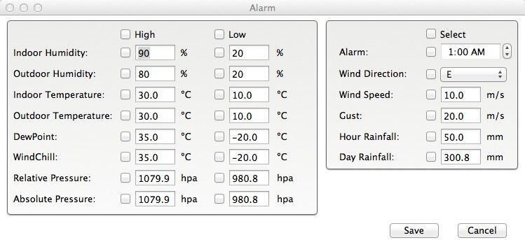
5    LCD description

Left top LCD:       IN-OUT temperature and humidity
Right top LCD:      Wind and rain measurement
Left middle LCD:    Weather forecast (tendency)
Right middle LCD:   Air pressure and air pressure history
Bottom line LCD:    Time and date, memory usage

Note:
The presence of the "Alarm On" icon in a section means that the particular alarm has been
enabled.

                                      © PCE Instruments
                                             4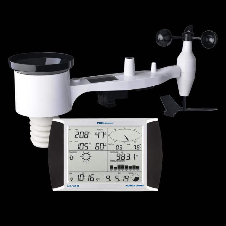
6     Getting started

6.1     Before first use
Before placing and installing all components of the weather station at their final destination, please
set up the weather station with all parts being nearby for testing the correct function.

6.2     Setting up the display and outdoor unit
Insert two LR6 (AA size) batteries into the outdoor unit. The LED located in the middle of the
bottom side of the case will be turned on for 4 seconds, then it will turn off and start to work
normally. The outdoor unit will make a data transmission and then start radio controlled time
reception routine. If a time signal can be detected correctly, the LED will flash 5 times and will
then be on for 20 seconds, indicating that the time signal has been found correctly. When the time
signal is bad and reception is not possible, the outdoor unit will terminate radio controlled time
reception within one minute and resume normal mode. When data have been transmitted, the
LED will be on for 20 ms. During radio controlled time reception period, there is no transmission
and normal transmission will only resume after time reception routine is complete. The longest
time for radio controlled time reception is 5 minutes.

After inserting the batteries into the weather station, all LCD segments will be turned on for a few
seconds for self-checking. The meter will then return to normal measuring mode und only the
display segments activated for the measurement will be active.

After this, the weather station will make an initial measurement and start to register the outdoor
unit (the radio reception icon will be turned on). Do not press any key before outdoor sensor data
are received, otherwise the outdoor sensor learning mode will be terminated. When the outdoor
unit has been registered, the display will automatically switch to normal display mode from which
all further settings can be performed by the user.

If no RCC/DCF signal is detected during the initial setup, the outdoor unit will try once every 6
hours to get an RCC/DCF signal. Once the outdoor unit receives the RCC/DCF signal, it will
transmit the signal to the monitor. On the monitor, the RCC/DCF icon will be displayed. If the
monitor does not receive the RCC/DCF signal or loses the signal, the RCC/DCF icon will not be
displayed.

Register outdoor unit
If no outdoor weather data is displayed or the signal to the sensors is lost during setup or
mounting, touch and hold the RESET button of the outdoor sensor and re-insert the batteries of
the display to synchronize the display with the sensors. Without being synchronized, weather data
will not be received.

Note:
Wait for two minutes before re-inserting the batteries of the outdoor unit for proper reset.

Note:
The best condition for reception is at night, between midnight and 6:00 am, when there is less
atmospheric interference.

                                        © PCE Instruments
                                               5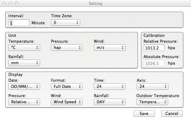
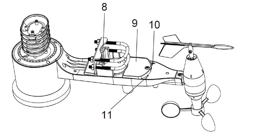
6.3     Sensors

1. Wind speed sensor
2. Wind vane
3. Thermo-hygro sensor
4. Rain collector
5. Bubble level
6. Solar panel
7. Antenna
8. U-bolt
9. Battery compartment
10. Reset button
11. LED indicator: light on for 4 s during startup.
    Then the LED will flash every 48 seconds (the sensor transmission update period).

                                     © PCE Instruments
                                            6
6.4 Install U-bolts and metal plate
The U-bolts are used to attach the sensors to a pole. Installation of the U-bolts, which are in turn
used to mount the sensor package on a pole, requires installation of the included metal plate to
fix the U-bolt ends. The metal plate, visible in the first picture below, has four holes through which
the ends of the two U-Bolts will fit. The plate itself is inserted into a groove at the bottom of the
unit (opposite side of solar panel). Note that one side of the plate has a straight edge (which goes
into the groove) whereas the other side is bent at a 90-degree angle and has a curved profile
(which will end up surrounding the mounting pole). Once the metal plate is inserted, insert both
U-bolts through the respective holes of the metal plate, as shown in the picture.
Loosely screw on the nuts on the ends of the U-bolts. You will tighten these later during final
mounting. Final assembly is shown in the following picture.
The plate and U-Bolts are not yet needed at this stage but installing these now may help avoid
damage to the wind vane and wind speed cups later on. Handling of the sensor package with
wind vane and speed cups installed prior to installing these bolts is more difficult and more likely
to lead to damage.
© PCE Instruments
76.5 Install wind speed cups
Push the wind speed cup unit onto the shaft on the top side of the sensor package, as shown on
the left side of the following picture. Tighten the set screw with a Philips screwdriver (size PH0),
as shown on the right-hand side. Make sure the cup unit can rotate freely. There should be no
noticeable friction when it is turning.
6.6 Install wind vane
Push the wind vane onto the shaft on the opposite side of the wind cups until it cannot be pushed
any further, as shown on the left side in the next picture. Then tighten the set screw with a Philips
screwdriver (size PH0), as shown on the right side, until the wind vane cannot be removed from
the shaft. Make sure the wind vane can rotate freely. The wind vane’s movement has a small
amount of friction, which is helpful in providing steady wind direction measurements.
© PCE Instruments
86.7 Install batteries
Open the battery compartment with a screwdriver and insert 2 AA batteries. The LED indicator
on the back of the sensor package will turn on for four seconds and then flash once every 48
seconds, indicating sensor data transmission (sensor transmission update period).
Note:
If the LED does not light up or glows permanently, make sure the battery is inserted correctly and
completely. Do not install the batteries backwards as this may permanently damage the outdoor
sensor.
Note:
We recommend lithium batteries for cold weather climates, but alkaline batteries are sufficient for
most climates. Rechargeable batteries have lower voltages and should never be used.
© PCE Instruments
96.8 Mount outdoor sensor
Before proceeding with the outdoor sensor mounting detailed in this section, you need to make
sure the display can receive data from outdoor sensor, while you keep the assembled outdoor
sensor package nearby (although preferably not closer than 1.5 m from the display). This will
make any troubleshooting and adjustments easier and avoids any distance or interference related
issues from the system.
After setup is complete and everything is working, return here for outdoor sensor mounting. If
issues show up after outdoor sensor mounting, they are almost certainly related to distance,
obstacles etc.
As you can see in the next picture, the mounting assembly includes two U-bolts and a bracket
that tightens around a 1 to 2” diameter pole (not included) using the four U-bolt nuts.
Note
Next to the antenna, there is an arrow icon with ”WEST” written below it (next picture),
representing the direction of west. The sensor body has to be adjusted so that the “WEST”
indication faces the real west direction in your location. A compass device is recommended to
help adjust the direction. A permanent wind direction error will occur when the outdoor sensor is
not installed in the right direction.
© PCE Instruments
10Now look at the bubble level. The bubble should be fully inside the red circle. If it is not, wind
direction, speed and rain readings may not be correct or accurate. Adjust the mounting pipe as
required. If the bubble is close but not quite inside the circle and you cannot adjust the mounting
pipe, you may have to experiment with small wooden or heavy cardboard shims between the
sensor package and the top of the mounting pole to achieve the desired result (this will require
loosening the bolts and some experimentation).
Make sure you check and - if necessary - correct the westward orientation as the final installation
step and tighten the bolts with a wrench.
6.9 Reset button and outdoor unit LED
Using a bent-open paperclip, touch and hold the RESET button (see picture) to do a reset: the
LED turns on while the RESET button is pressed. You can then release it. The LED should then
resume as normal, flashing approximately once every 48 seconds.
RESET button
LED light
6.10 Basic operation
All actions and functions of the weather station are started on the touch screen by slightly touching
(not pressing!) the related areas. Touch the flashing “+”, “ON/OFF” or “–“ icons to make a selection
or to increase/decrease a value. Everytime a programming step is activated by touching a
switching area on the touch screen, a tone will sound and the backlight is switched on for a few
seconds. If no areas are pressed for 30 seconds, the LCD will automatically revert to normal
display mode (automatic timeout).
© PCE Instruments
116.11 Best practices for wireless communication
Note:
To ensure proper communication, mount the remote sensor(s) upright on a vertical surface such
as a wall. Do not lay the sensor flat.
Wireless communication is susceptible to interference, distance, walls and metal barriers. We
recommend the following best practices for trouble-free wireless communication.
1. Electro-Magnetic Interference (EMI): Keep the display several feet away from
computer monitors and TVs.
2. Radio Frequency Interference (RFI): If you have other 433/868/915 MHz devices and
communication is intermittent, try turning off these other devices. You may need to
relocate the outdoor units or receivers to avoid intermittent communication.
3. Line of Sight Rating: This device is rated at 300 feet line of sight (no interference,
barriers or walls) but typically, you will get 100 feet maximum under most real-world
installations, which include passing through barriers or walls.
4. Metal Barriers: Radio frequency will not pass through metal barriers such as aluminum
siding. If you have metal siding, align the outdoor unit and display through a window to
get a clear line of sight.
The following is a table of the transmission medium vs.reception loss. Each “wall” or obstruction
decreases the transmission range by the factor shown below.
Medium RF signal strength reduction
Glass (untreated) 5 … 15 %
Plastics 10 … 15 %
Wood 10 … 40 %
Brick 10 … 40 %
Concrete 40 … 80 %
Metal 90 … 100 %
7 Operation
Note:
Because of the default settings already determined by the manufacturer, it may not be necessary
for the majority of users to perform – except the relative air pressure (see further down) - any
further basic settings. Changes, however, can be easily made.
For basic settings, the following menu is started by touching the touch screen in the desired
display area.
The basic settings can now be performed in the following successive order:
Note:
The setting procedure can be exited at any time by touching any other function area (except “+”,
“-” or “ON/OFF”).
© PCE Instruments
127.1 Indoor temperature
Make indoor temperature settings as follows:
1) Touch the INDOOR TEMPERATURE section, the + and – buttons will be flashing.
Touch the + or – button to change the display unit (°C or °F).
2) Touch the INDOOR TEMPERATURE section again to set the indoor temperature high
alarm function, the +, ON/OFF and – buttons will be flashing, the HI AL icon will light
up. Touch the+ or – button to change the value, hold the+ or – button for 3 s to change
the number in larger steps. Touch the ON/OFF button to turn the alarm on or off (if
alarm is enabled, the speaker icon will be turned on, indicating the alarm function has
been enabled).
3) Touch the INDOOR TEMPERATURE section the third time to set the indoor
temperature low alarm function, the +, ON/OFF and – buttons will be flashing, the LO
AL icon will light up. Touch the+ or – button to change the value, touch and hold the+
or – button for 3 s to change the number in larger steps. Touch the ON/OFF button to
turn the alarm on or off (if alarm is enabled, the speaker icon will be turned on).
4) Touch the INDOOR TEMPERATURE section the fourth time to display the maximum
indoor temperature record. The maximum record will flash and the MAX icon will light
up. After holding the flashing MAX value for 3 s, the maximum value will be reset to
current reading.
5) Touch the INDOOR TEMPERATURE section the fifth time to display the minimum
indoor temperature record. The minimum record will flash and the MIN icon will light up.
After holding the flashing min value for 3 s, the minimum value will be reset to current
reading.
© PCE Instruments
137.2 Outdoor temperature
Make outdoor temperature settings as follows:
1) Touch the OUTDOOR TEMPERATURE section, the + and – buttons will flash. Touch
the + or – button to shift the display between outdoor temperature, wind chill and dew
point.
2) Touch the OUTDOOR TEMPERATURE section again, the + and – buttons will flash.
Touch the + or – button to shift the display unit between °C and °F.
3) Touch the OUTDOOR TEMPERATURE section the third time to set the outdoor
temperature high alarm function. The +, ON/OFF and – buttons will flash, the HI AL icon
will light up. Touch the+ or – button to change the value, hold the+ or – button for 3 s to
change the number in larger steps. Touch the ON/OFF button to turn the alarm on or
off (if alarm is enabled, the speaker icon will be turned on, indicating the alarm function
has been enabled).
4) Touch the OUTDOOR TEMPERATURE section the fourth time to set the outdoor
temperature low alarm function. The +, ON/OFF and – buttons will flash, the LO AL icon
will light up. Touch the + or – button to change the value, touch and hold the + or –
button for 3 s to change the number in larger steps. Touch the ON/OFF button to turn
the alarm on or off (if alarm is enabled, the speaker icon will be turned on).
5) Touch the OUTDOOR TEMPERATURE section the fifth time to display the maximum
outdoor temperature record. The recorded maximum value will flash, the MAX icon will
light up. After holding the flashing MAX value for 3 s, the maximum value will be reset
to current reading.
6) Touch the OUTDOOR TEMPERATURE section the sixth time to display the minimum
outdoor temperature record. The recorded minimum value will flash, the MIN icon will
light up. After holding the minimum value for 3 s, the minimum value will be reset to
current reading.
© PCE Instruments
147.3 Indoor humidity
Make indoor humidity settings as follows:
1) Touch the INDOOR HUMIDITY section to set the indoor humidity high alarm function.
The +, ON/OFF and – buttons will flash, the HI AL icon will light up. Touch the + or –
button to change the value, touch and hold the + or – button for 3 s to change the
number in larger steps. Touch the ON/OFF button to turn the alarm on or off (if alarm
is enabled, the speaker icon will be turned on, indicating the alarm function has been
enabled).
2) Touch the INDOOR HUMIDITY section again to set the indoor humidity low alarm
function. The +, ON/OFF and – buttons will flash, the LO AL icon will light up. Touch
the + or – button to change the value, touch and hold the+ or – button for 3 s to change
the number in larger steps. Touch the ON/OFF button to turn the alarm on or off (if
alarm is enabled, the speaker icon will be turned on, indicating the alarm function has
been enabled).
3) Touch the INDOOR HUMIDITY section the third time to display the maximum indoor
humidity record. The recorded maximum value will flash and the MAX icon will light up.
After holding the maximum value for 3 s, the maximum value will be reset to current
reading.
4) Touch the INDOOR HUMIDITY section the fourth time to display the minimum indoor
humidity record. The recorded minimum value will flash and the MIN icon will light up.
After holding the minimum value for 3 s, the minimum value will be reset to current
reading.
7.4 Outdoor humidity
Procedures and settings are similar to indoor humidity.
© PCE Instruments
157.5 Wind speed/direction
Make wind settings as follows:
1) Touch the WIND SPEED section, the + and – buttons will flash. Touch the + or – button
to shift the display between average wind speed and gust speed.
2) Touch the WIND SPEED section again, the + and – buttons will flash. Touch the + or –
button to select the wind speed unit: km/h, mph, m/s, knots or bft.
3) Touch the WIND SPEED section the third time to set the high alarm function, the +,
ON/OFF and – button will flash, the HI AL icon will light up. Touch the + or – button to
change the value, touch and hold the+ or – button for 3 s to change the number in larger
steps. Touch the ON/OFF button to turn the alarm on or off (if alarm is enabled, the
speaker icon will be turned on, indicating the alarm function has been enabled).
4) Touch the Wind SPEED section the fourth time to set the wind direction alarm function,
the wind direction arrow will start flashing. Touch + or – to select the desired alarm for
the wind direction. Press ON/OFF to enable or disable the wind direction alarm.
5) Touch the Wind SPEED section the fifth time to display the maximum wind speed
record. The recorded maximum value will flash and the MAX icon will light up. After
holding the maximum value for 3 s, the maximum value will be reset to current reading.
© PCE Instruments
167.6 Rain
Make rain settings as follows:
1) Touch the RAIN section, the + and – buttons will flash. Touch the + or – button to shift
the display between 1 h, 24 h, week, month and total rain.
2) Touch the RAIN section again. The + and – buttons will flash. Touch the + or – button
to select the rainfall unit: mm or inch.
3) Touch the RAIN section the third time to set the high alarm function. The +, ON/OFF
and – buttons will flash and the HI AL icon will light up. Touch the + or – button to
change the value, hold the + or – button for 3 s to change the number in larger steps.
Touch the ON/OFF button to turn the alarm on or off (if alarm is enabled, the speaker
icon will be turned on, indicating the alarm function has been enabled).
4) Touch the RAIN section the fourth time to display the current maximum rainfall record.
Touch the flashing MAX value for 3 s to reset the maximum rainfall value to current
value.
5) Touch the RAIN section the fifth time to reset the rainfall value to 0 by holding the
flashing reading for 3 s. Then 1 h, 24 h, week, month and total rain will be reset to 0.
© PCE Instruments
177.7 Weather forecast
1) Touch the TENDENCY section. The + and – buttons will flash. Touch the + or – button
to switch the displayed icon between SUNNY, PARTLY CLOUDY, CLOUDY and
RAINY.
2) Touch the TENDENCY section again. The + and – buttons will flash. Touch the + or –
button to set the pressure threshold from 2 … 4 hPa (default: 2 hPa).
3) Touch the TENDENCY section the third time. The + and – button will flash. Touch the
+ or – button to set the storm threshold from 3. … 9 hPa (default: 4 hPa).
© PCE Instruments
187.8 Pressure
1) Touch the PRESSURE section. The + and – buttons will flash. Touch the + or – button
to shift the display between absolute pressure and relative pressure.
2) Touch the PRESSURE section again. The + and – buttons will flash. Touch the + or –
button to shift the display unit between hPa, inHg and mmHg.
3) Touch the PRESSURE section the third time to set the relative pressure value. The +
and – buttons will flash, the “rel” icon will light up. Touch the + or – button to change
the value. Hold the + or – button for 3 s to change the number in larger steps.
4) Touch the PRESSURE section the fourth time to set the pressure high alarm function.
The +, ON/OFF and – buttons will flash and the HI AL icon will light up. Touch the + or
– button to change the value, hold the + or – button for 3 s to change the number in
larger steps. Touch the ON/OFF button to turn the alarm on or off (if alarm is enabled,
the speaker icon will be turned on, indicating the alarm function has been enabled).
5) Touch the PRESSURE section the fifth time to set the pressure low alarm function. The
+, ON/OFF and – buttons will flash and the LO AL icon will light up. Touch the + or –
button to change the value, hold the + or – button for 3 s to change the number in larger
steps. Touch the ON/OFF button to turn the alarm on or off (if alarm is enabled, the
speaker icon will be turned on, indicating the alarm function has been enabled).
6) Touch the PRESSURE section the sixth time to display the maximum pressure record.
The recorded maximum value will flash and the MAX icon will light up. After holding the
maximum value for 3 s, the maximum value will be reset to current reading.
7) Touch the PRESSURE section the seventh time to display the minimum pressure
record. The recorded minimum value will flash and the MIN icon will light up. After
holding the minimum value for 3 s, the minimum value will be reset to current reading.
Note:
When absolute pressure is selected, step 3 will be skipped.
© PCE Instruments
197.9 Pressure bar graph
Touch the PRESSURE BAR GRAPH section and then press + or – to toggle the bar graph time
scale between 12 hrs or 24 hrs for pressure history.
7.10 Time
1) Touch the TIME section. The + and – buttons will flash. Touch the + or – button to
adjust the contrast level between 0 and 8. (default: 5)
2) Touch the TIME section again. The + and – buttons will flash. Touch the + or – button
to set the time zone.
3) Touch the TIME section the third time. The + and – buttons will flash. Touch the + or –
button to shift between 12/24 hours format.
4) Touch the TIME section the fourth time to set the hour. The + and – buttons will flash.
Touch the + or – button to change the value.
5) Touch the TIME section the fifth time to set the minute. The + and – buttons will flash.
Touch the + or – button to change the value.
7.11 Date
1) Touch the DATE section. The + and – buttons will flash. Touch the + or – button to shift
between alarm time, date and weekday.
2) Touch the DATE section again, the + and – buttons will flash. Touch the + or – button
to shift between DD-MM format and MM-DD format for the date.
3) Touch the DATE section the third time. The + and – buttons will flash. Touch the + or –
button to set the year. Hold the + or – button for 3 s to change the number in larger
steps.
4) Touch the DATE section the fourth time. The + and – buttons will flash. Touch the + or
– button to set the month. Hold the+ or – button for 3 s to change the number in larger
steps.
5) Touch the DATE section the fifth time. The + and – buttons will flash. Touch the + or –
button to set the day. Hold the + or – button for 3 s to change the number in larger
steps.
6) Touch the DATE section the sixth time. The + and – buttons will flash. Touch the + or
– button to set the alarm hour. Hold the+ or – button for 3 s to change the number in
larger steps.
7) Touch the DATE section the seventh time. The + and – buttons will flash. Touch the +
or – button to set the alarm minute. Hold the + or – button for 3 s to change the number
in larger steps. Touch ON/OFF to enable or disable the time alarm function.
© PCE Instruments
207.12 Memory
Touch the MEMORY section to activate history data toggle display. The + and – buttons will flash.
Press – to toggle forward to see earlier weather history data together with their time stamp. Press
+ to see later history weather data. When history data are displayed, the corresponding time will
be displayed in the time section (History data saving interval can only be changed using the PC
software that can be downloaded for this product. The default history data saving time interval is
30 minutes).
Touch the MEMORY section again to trigger the memory clear procedure: the word “CLEAR” as
well as the full memory icon will flash. Touch and hold the memory full icon for 3 seconds to clear
the memory.
8 Maintenance
1. Clean the rain gauge once every 3 months. Rotate the funnel counter-clockwise, lift it
to expose the inside of the rain gauge and clean it with a damp cloth. Remove any dirt,
debris and insects. If bug infestation is an issue, spray the rain gauge lightly with
insecticide.
2. Clean the solar panel every 3 months with a damp cloth.
3. Replace the batteries every 1 to 2 years. If left in too long, the batteries may leak due
to environmental challenges. In harsh environments, inspect the batteries every 3
months (when cleaning the solar panel).
4. When replacing the batteries, apply a corrosion preventive compound on the battery
terminals, available at most hardware stores.
5. In snowy environments, spray the top of the weather station with anti-icing / silicon
spray to prevent snow build up.
9 PC connection
As an important feature in addition to displaying data on the touch screen, the weather station
allows the read-out of all measured and displayed time and weather data in the form of complete
history data sets on a PC.
9.1 Data storage
For a comprehensive weather history, the display allows the internal storage of up to 4080
complete sets of weather data with time and date. The display will lose all weather data when the
power supply is interrupted. In case the memory capacity of the weather station is exhausted, the
oldest data sets stored will be overwritten by the new ones entered.
9.2 Data recall
Certain weather data or set values can only be read out, processed and displayed by means of a
PC. Also, setting the storage interval from 5 minutes to 240 minutes for the storage of data sets
can only be performed by means of a PC.
© PCE Instruments
219.3 Connections and software
The wiring between the weather station and the PC is done by means of an included USB cable.
This software allows displaying all present weather data with graphic symbols.
It also allows the display, storage, and printing of history data sets the volume of which is not
limited to a maximum of 4080 data sets, as in the weather station itself, but is only limited by the
capacity of the PC’s main memory.
9.4 PC software installation
The installation of the software is described in further detail under 10.2.
If you run the program for the first time, the current weather data will be displayed and in the sub
line of the window, the program will show the status of data upload to the software. Please note,
however, when a large amount of data is being uploaded, it will take a few minutes before the
system can respond to your settings.
When the memory is full, it will take about two minutes to upload all history data to the PC and
another two minutes to process all history data for graphic display.
© PCE Instruments
2210 Software
10.1 System Requirements
To install the "EasyWeather" software on your PC, the minimum requirements are as follows:
Operating system: Windows 7/8/10, MAC OS
Internet Explorer 6.0 or above
Processor: 500 MHz or above
Memory: at least 128 MB, 256 MB recommended
CD-ROM drive
Display and PC must be connected by USB cable
10.2 Installation of the “EasyWeather” software
The display and the outdoor sensors must be connected and checked for correct function.
After successfully checking proper function of the weather station, install the “EasyWeather”
software as follows:
1. Switch on your PC and download the software here:
https://www.pce-instruments.com/english/download-win_4.htm.
2. Unzip the downloaded zip file.
3. Double-click “Easyweather Setup.exe”.
4. Select the language and click “OK”.
5. Click “Next” and select the storage location.
6. Click “Next” to install the programme.
7. Clcik “OK” to finish the installation process.
8. The programme is to be found under “Start - EasyWeather”.
Note:
The user should be aware that to fully access the graphic functions, they need to have
administrative rights for the computer.
© PCE Instruments
2310.3 Basic settings of the PC software
After the start-up of the “EasyWeather.exe” programme, the following window will appear on the
PC screen:
The settings from the display are transferred to the PC software. Once the settings of the display
have been completed, no settings need to be made in the PC software. However, it is easy to
change the settings in the PC software and transfer these to the display (The settings will be
updated in the display in the next full minute). When the display is connected to the PC, it shows
“USB Connected” at the bottom of the screen. If no display is connected, it shows ”USB
Unconnected”.
10.4 System menu
© PCE Instruments
2410.4.1 Basic settings
This section is used to set the PC software display as well as the display units. Press the “Save”
button to confirm the settings.
© PCE Instruments
2510.4.2 Alarm settings
This section is used to set the desired time, a higher or lower warning value and to enable or
disable an alarm function. Press the “Save” button to confirm the settings. If you do not need to
change any of the settings, press “Cancel” and exit.
© PCE Instruments
2610.4.3 Max/Min display
This section is used to display the recorded Min and Max value values with a time stamp. A
Min/Max reset can only be carried out on the display.
10.4.4 Language setting
© PCE Instruments
2710.5 Save
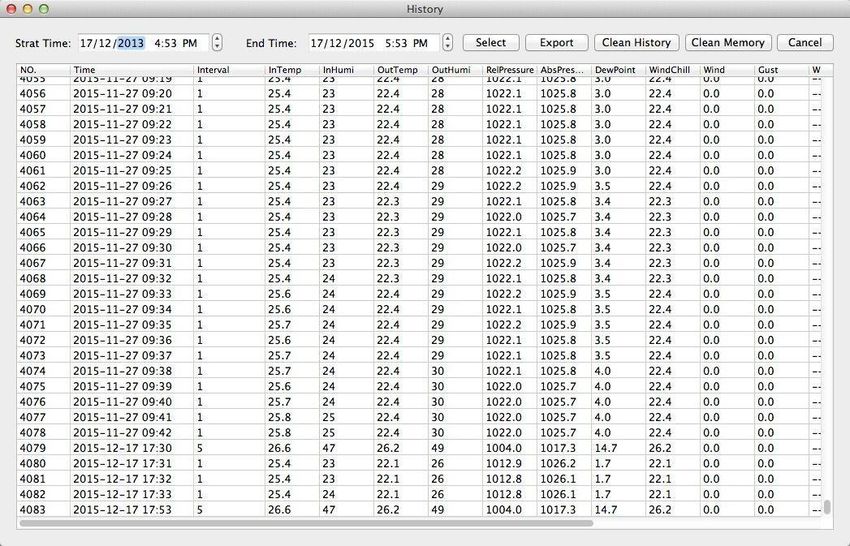
10.5.1 Tabular view
This section is used to display saved data in a spread sheet. To view data from a desired time
period, enter the time period and click on “Search” to reload the history data. The “Export as csv”
button exports the selected saved data into an Excel file for use in other applications.
The software version 6.2 uses .dat file format, software versions above 6.2 use .mdb format. Click
on the “Import” button to import the data from the old version to the new version.
When the memory of the display is full, click on the “Clear Memory” button to refresh the memory
space of the display (remember to upload all data before pressing this button).
If you would like to start a new weather history record, click on the “Clear Data” button and all the
recorded data will be deleted.
If you would like to keep a backup history file before deleting all weather data, you can make a
copy of the “EasyWeather.mdb” file into another folder or just rename the “EasyWeather.mdb”
file, such as “Jan-07.dat”, for future reference..
© PCE Instruments
2810.5.2 Graphical view
In this section, the saved data can be viewed in graph format. If you want to view the data in more
detail, use the mouse to select the area and the display will automatically be updated in more
detailed scale:
The y axis can be changed by scrolling the mouse wheel.
© PCE Instruments
29The “Export as image“ button exports the selected graph into a jpeg image.
10.6 Troubleshooting: Graphs are not displayed
This is the most encountered problem with this software. To make sure the graph is displayed,
proceed as follows:
1. Find the folder in which the “EasyWeahter.exe” file is located.
2. Create a file called “reg_graph.bat” with word pad or notepad editor programme
(Make sure that Windows saves the file with the correct ending and not as
“reg_graph.bat.txt” – the file name in front of the point is not relevant).
3. Type “regsvr32 easyweather.ocx” (without quotation marks) into the text editor and
save the reg_graph.bat file.
4. Double-click on the created reg_graph.bat file – The following message confirms that
the command has been successfully executed:
© PCE Instruments
3010.7 Data upload
Note:
This function is available from Version 8.3. The current version is available for download on
https://www.pce-instruments.com/english/download-win_4.htm.
To upload weather data to the internet, from EasyWeather, select “Upload” from the menu bar.
10.7.1 Upload to WeatherUnderground.com
The saved measurement data can be uploaded to www.wunderground.com. Register on
www.wunderground.com free of charge. Select “Join” if you do not have an account yet.
Then visit http://www.wunderground.com/weatherstation/setup.asp and enter your station’s ID (in
capital letters) and password (case-sensitive). Tick the “Auto Upload” checkbox.
Alternatively, the data can be uploaded to your own website. In that case, you have to choose
“Custom” and set the server, server type and port.
© PCE Instruments
3110.7.2 Upload to WeatherCloud
© PCE Instruments
3210.7.3 Upload your weather data to WeatherObservationWebsite (WOW)
Select “Upload” – “WeatherObservationWebsite” from the menu bar.
To upload data to wow.metoffice.gov.uk, you must first register on the wow.metoffice.gov.uk
website. Registration is free.
Once you are logged in, you will need to create a new WOW site. “Sites” are the means by which
WOW organizes weather data you contribute. Basically, WOW builds a personal web site for your
weather station. The following two items you need to upload data are associated with the web
site.
Site ID: This is an arbitrary number that is used to distinguish your site from another. This number
appears (in brackets) next to or below the name of your site on the site information page, for
example: 6a571450-df53-e611-9401-0003ff5987fd.
Authentication key: This is a 6-digit number that is used to ensure data is coming from you and
not another user.
Start setting up a new site by clicking on “Enter a Site”:
You will see a form where you detail your station’s location and some other settings related to
how you wish the site to operate. After you complete the setup, you should see:
© PCE Instruments
33Make sure you are (still) logged in to the WOW site. Log in when necessary. Now click on “My
Sites” in the navigation bar at the top. If you have only 1 site, you will now be shown its page. If
you have multiple sites, you will have to select one first. On this page, you will find the site ID
just below the map:
You will also need to create a unique 6-digit PIN code that you should keep secret. It is the
“Authentication Key.” Set up this number by clicking on “Edit Site” and entering a 6-digit number
of your choice:
You will need both “Site ID” and “Authentication Key” to set up the upload configuration for WOW
in the weather server.
On the WOW website, navigate to the “Device List” page and tap on the device you want to
configure WOW for. You will then be shown the “wunderground.com” configuration. Please ignore
and tap “Next” to see the “Weathercloud” configuration. Please press “Next” one more time and
you will get to the screen where you can configure WOW.
On this screen, you will enter the WOW “Site ID” as “Station ID” and the WOW “Authentication
Key” you created as “Station Key”. Press “Save” to finalize the configuration.
10.8 Help option
Click on the “About EasyWeather” button to enter the “About” menu.
© PCE Instruments
3411 Software on MAC OS
11.1 Installation of the “EasyWeather” software
The display and the outdoor sensors must be connected and checked for correct function.
After successfully checking proper function of the weather station, install the “EasyWeather”
software as follows:
1. Switch on your MAC and download the software here:
https://www.pce-instruments.com/english/download-win_4.htm.
2. Unzip the downloaded zip file.
3. Double-click the “EasyWeather” icon in the MAC folder. The following screen will
open:
The functions of MAC OS are the same as the Windows version. Once the device is connected
to a MAC by the USB cable, settings and alarms of all weather parameters can be entered here.
The Max/Min record and all history records can be viewed. History records can be exported as
Excel or PDF files as well.
© PCE Instruments
3511.2 Basic settings
Please refer to 10.4.1
11.3 Alarm settings
Please refer to 10.4.2
© PCE Instruments
3611.4 Max/Min display
Please refer to 10.4.3
11.5 Save
Please refer to 10.5.1
© PCE Instruments
3711.6 Graphical view
Please refer to 10.5.2
11.7 Data upload
Please refer to 10.7
© PCE Instruments
3811.8 Check software version
Click on the “About EasyWeather” button to enter the “About” menu to check version
information.
11.9 Special notes about time synchronization between PC/MAC and display
The PC software obtains its own time scale through the time interval marker from the display
history data and the PC software automatically synchronizes the weather data with a time stamp
calculated. Thus, the history data file can have a different time when the PC/MAC time and display
time are not same. In order to make sure the time scale is correct and to avoid data from being
overwritten or missed, set the same time for the PC/MAC as for the display. If the saved history
of weather data of the display is cleared manually, the history of weather data since the last upload
is lost permanently.
Before the memory is used up (memory icon on LCD display showing 100 % full), remember to
upload your history of weather data to the PC/MAC periodically.
If the rainfall has been reset on the display, there will be a rainfall value discrepancy between the
PC/MAC and the display.
© PCE Instruments
3912 Warranty
You can read our warranty terms in our General Business Terms which you can find here:
https://www.pce-instruments.com/english/terms.
13 Disposal
For the disposal of batteries in the EU, the 2006/66/EC directive of the European Parliament
applies. Due to the contained pollutants, batteries must not be disposed of as household waste.
They must be given to collection points designed for that purpose.
In order to comply with the EU directive 2012/19/EU we take our devices back. We either re-use
them or give them to a recycling company which disposes of the devices in line with law.
For countries outside the EU, batteries and devices should be disposed of in accordance with
your local waste regulations.
If you have any questions, please contact PCE Instruments.
© PCE Instruments
40PCE Instruments contact information
Germany France Spain
PCE Deutschland GmbH PCE Instruments France EURL PCE Ibérica S.L.
Im Langel 4 23, rue de Strasbourg Calle Mayor, 53
D-59872 Meschede 67250 Soultz-Sous-Forets 02500 Tobarra (Albacete)
Deutschland France España
Tel.: +49 (0) 2903 976 99 0 Téléphone: +33 (0) 972 3537 17 Tel. : +34 967 543 548
Fax: +49 (0) 2903 976 99 29 Numéro de fax: +33 (0) 972 3537 18 Fax: +34 967 543 542
info@pce-instruments.com info@pce-france.fr info@pce-iberica.es
www.pce-instruments.com/deutsch www.pce-instruments.com/french www.pce-instruments.com/espanol
Germany United Kingdom Italy
Produktions- und PCE Instruments UK Ltd PCE Italia s.r.l.
Entwicklungsgesellschaft mbH Unit 11 Southpoint Business Park Via Pesciatina 878 / B-Interno 6
Im Langel 26 Ensign Way, Southampton 55010 Loc. Gragnano
D-59872 Meschede Hampshire Capannori (Lucca)
Deutschland United Kingdom, SO31 4RF Italia
Tel.: +49 (0) 2903 976 99 471 Tel: +44 (0) 2380 98703 0 Telefono: +39 0583 975 114
Fax: +49 (0) 2903 976 99 9971 Fax: +44 (0) 2380 98703 9 Fax: +39 0583 974 824
info@pce-instruments.com info@pce-instruments.co.uk info@pce-italia.it
www.pce-instruments.com/deutsch www.pce-instruments.com/english www.pce-instruments.com/italiano
The Netherlands Chile Hong Kong
PCE Brookhuis B.V. PCE Instruments Chile S.A. PCE Instruments HK Ltd.
Institutenweg 15 RUT: 76.154.057-2 Unit J, 21/F., COS Centre
7521 PH Enschede Calle Santos Dumont N° 738, Local 4 56 Tsun Yip Street
Nederland Comuna de Recoleta, Santiago Kwun Tong
Telefoon: +31 (0)53 737 01 92 Tel. : +56 2 24053238 Kowloon, Hong Kong
Fax: +31 53 430 36 46 Fax: +56 2 2873 3777 Tel: +852-301-84912
info@pcebenelux.nl info@pce-instruments.cl jyi@pce-instruments.com
www.pce-instruments.com/dutch www.pce-instruments.com/chile www.pce-instruments.cn
United States of America Turkey China
PCE Americas Inc. PCE Teknik Cihazları Ltd.Şti. PCE (Beijing) Technology Co., Limited
711 Commerce Way suite 8 Halkalı Merkez Mah. 1519 Room, 6 Building
Jupiter / Palm Beach Pehlivan Sok. No.6/C Zhong Ang Times Plaza
33458 FL 34303 Küçükçekmece - İstanbul No. 9 Mentougou Road, Tou Gou District
USA Türkiye 102300 Beijing
Tel: +1 (561) 320-9162 Tel: 0212 471 11 47 China
Fax: +1 (561) 320-9176 Faks: 0212 705 53 93 Tel: +86 (10) 8893 9660
info@pce-americas.com info@pce-cihazlari.com.tr info@pce-instruments.cn
www.pce-instruments.com/us www.pce-instruments.com/turkish www.pce-instruments.cn
© PCE Instruments
41You can also read