MSR_SAFE Intel Power Management & - Dr. Daniele Cesarini, HPC Software Engineer, CINECA Dr. Robert Schöne, Faculty Computer Science, TU Dresden
←
→
Page content transcription
If your browser does not render page correctly, please read the page content below
Intel Power Management
 &
 MSR_SAFE
 Energy Efficiency in HPC, IT4Innovation, Ostrava (CZ), 29 January 2020

 Dr. Daniele Cesarini, HPC Software Engineer, CINECA
Dr. Robert Schöne, Faculty Computer Science, TU Dresden

And God said, Let there be light: and there was light.
And God saw the light, and it was good; and God divided the light
from the darkness.
Maxwell’s Equations

 Third verse of the Book of Genesis

What is ACPI?
ACPI (Advanced Configuration and Power Interface) is an open industry specification co-developed by
Hewlett-Packard, Intel, Microsoft, Phoenix, and Toshiba. ACPI establishes industry-standard interfaces
enabling OS-directed configuration, power management, and thermal management of mobile, desktop, and
server platforms.
 We will focus on
 Global system states (g-state) G0 states of
 Applications G0 : Working (e.g. running and idle) Intel architecture!

 OS Power Management G1 : Sleeping (e.g., suspend, hibernate)
 ACPI G2 : Soft off (e.g., powered down but can be restarted by
 Software drivers interrupts from input devices)

 Hardware: CPU, BIOS etc. G3 : Mechanical off
 Lower number means higher power

 CPUs implement mechanisms to support these states.

 BIOS and software drivers hide the difference of CPU implementations to support the ACPI
 defined data structures and functions.
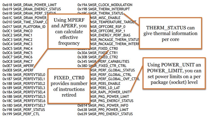
Enhanced Intel SpeedStep
 Technology
 EIST (aka Software Intel P-states)
 ACPI defines performance states (P-States)
 • P-States correspond to different performance levels that are applied while the processor is actively executing
 instructions.
 • P-state is frequency and voltage operating point, both are scaled as the P-State increases.
 • The driver provides an interface to control the P-State selection for the SandyBridge+ Intel processors.
 • P-state takes advantages of turbo boost to increase the performance (core frequency higher than nominal).

 2.4 • Cores which share the same voltage domain vote for a p-state
 GHz
 2.1 • The highest p-state for each core wins
 GHz P0
Power (W)

 1.8
 1.2 1.5 GHz P1
 GHz GHz • Voltage regulator per core
 P2
 Pn P3 • Don’t need to vote for a common-state
 Core Voltage (V) • Each core has its own P-State
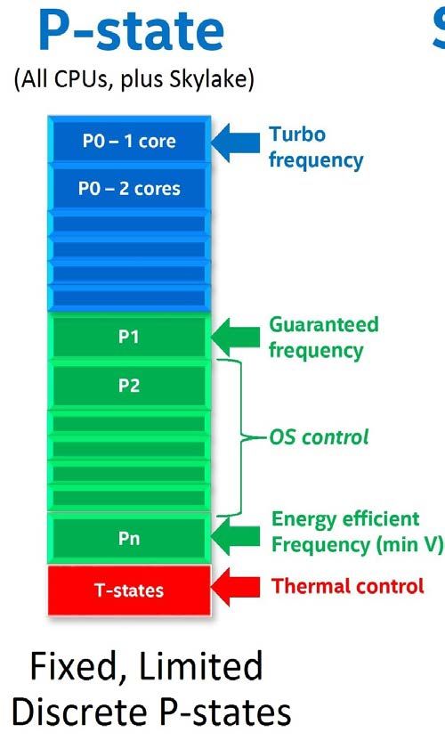
Turbo Boost Technology
 Turbo Boost is an Intel technology that opportunistically allows the processor to run faster than the nominal frequency if
 the CPU is operating below power, temperature and current limits. Turbo Boost is not overclocking!
 • Operates under OS control – only entered when OS requests higher performance state (P0).
 • Max Turbo Boost frequency is dependent on the number of active cores and varies by processor.
 • Turbo Boost will depend on workload, operating environment, and platform design.
 • Turbo Boost frequency is selected by the firmware of the CPU (no OS control).
 • Maximum turbo frequency is related to the number of active core (CPU version and architecture dependent).
 • Turbo frequency is related to the mix of instructions executed in the last period of time not from CPU thermal condition (turbo frequency
 for SIMD instructions ≠ scalar instructions).
 • Energy efficient turbo* attempts to reduce the usage of turbo frequencies that do not significantly increase the performance monitoring
 the stall cycles and selecting a next frequency that is predicted to be optimal. It is driven by the “Energy Performance BIAS Hint” setting.
 • Turbo Boost Technology 3 -> use the core with the best performance per power for single threaded applications

*World Intellectual Property Organization
International Publication Number:
WO 2013/137859 Al
Pub. Date: Sep. 19, 2013

Performance and Energy
 Bias Hint support
Intel 64 processors may support additional software hint to guide the hardware heuristic of power
management features to favor increasing dynamic performance or conserve energy consumption (affect
Turbo boost and Uncore Frequency Scaling).

• Software can program the lowest four bits of IA32_ENERGY_PERF_BIAS (0x1B0) MSR with a value from 0 - 15.
• Value of 0: corresponds to a hint preference for highest performance
• value of 15: corresponds to the maximum energy savings.
• A value of 7 (default) roughly translates into a hint to balance performance with energy consumption.

 Sysfs interface: /sys/devices/system/cpu/cpu*/power/energy_perf_bias
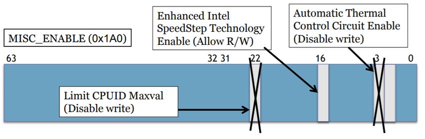
Intel P-State
 Machine Specific Registers (MSR)
Intel P-State driver make state transitions writing a 16-bit value to the IA32_PERF_CTL (0x198) register. Reads of
IA32_PERF_CTL (0x199) determine the targeted operating point. If a transition is already in progress, transition to a new
value will subsequently take effect. The current operating point can be read from IA32_PERF_STATUS.
IA32_PERF_STATUS is updated dynamically when target p-state is reached. Turbo boost can be also enabled/disabled by
IA32_MISC_ENABLE (0x1A0) registers.

 IA32_PERF_STATUS

 IA32_PERF_CTL

 IA32_MISC_ENABLE
 Turbo boost
 enable/disable

Hardware-coordination feedback
 mechanism APERF/MPERF
 MPERF (0xE7) is a counter that increments itself relative at the nominal frequency at every cycle in C0 status. While,
 APERF (0xEB) increments itself coordinated at clock frequency in C0 status. Current P-state is computed like:
 P-state = (delta_APERF / delta_MPERF) * max_pstate
 APERF and MPERF are calculated as a different over a measurement interval. The interval is defined to be
 the time between successive reads (delta_X) on that core.

 IA32_MPERF

 IA32_APERF

Trick: APERF/MPERF can be also used to check the average frequency in the last period of time:
 CPU freq = (delta_APERF / delta_MPERF) * nominal_freq

Intel SpeedShift Technology
 HWP (aka Hardware P-States)
If the processor is capable of selecting its next P-State internally, then the driver will offload this responsibility to the
processor (aka HWP: Hardware P-States). Skylake and newer architectures equip Intel SpeedShift Technology.

 • Speed Shift vs P-state transitions
 • Speed Shift : 1 ms
 • P-state: 10 ms
 • From efficient power state to
 maximum performance
 • Speed Shift: 35 ms
 • P-state: 100 ms
Configuration of
Intel SpeedShift Technology (HWP)
Uncore Frequency Scaling
 Characteristics:
 • The uncore frequency is set transparently for operating system and user.
 • Uncore frequency is stalled when Package C-state enter in C3 or deeper state.
 • The choice of uncore frequency is driven by the number of active cores and the traffic on the
 on-chip interconnect.
 • The uncore frequency scaling partly base their frequency decisions on the “Energy performance
 BIAS Hints” setting.
 • Uncore frequency is bounded to a max and a min frequency range specified in the
 “MSR_UNCORE_RATIO_LIMIT”.
 Trick: if max and min parameters are set to the same value the uncore frequency doesn't change!

 https://patentimages.storage.googleapis.com/bb/a2/44/354a91cab2e94e/US20140208141A1.pdf
United States Patent Application Publication Pub. No.: US 2014/0208141 A1 Bhandaru et al. Pub. Date: Jul. 24, 2014
Sysfs for intel_pstate (and cpufreq)
Sysfs Interface: /sys/devices/system/cpu/intel_pstate/*
• max_perf_pct: Maximum P-state the driver is allowed to set in percent of the maximum supported performance level (the highest supported turbo P-state).
• min_perf_pct: Minimum P-state the driver is allowed to set in percent of the maximum supported performance level (the highest supported turbo P-state).
• turbo_pct: Ratio of the turbo range size to the size of the entire range of supported P-states, in percent.
• status: Operation mode of the driver: “active”, “passive” or “off”.
• num_pstates: Number of P-states supported by the processor (between 0 and 255 inclusive) including both turbo and non-turbo P-states.
• no_turbo: If set (equal to 1), the driver is not allowed to set any turbo P-states.
• hwp_dynamic_boost: (equal to 1) controls the hardware P-States booting. Allowing intel_pstate to use iowait boosting in the active mode with HWP enabled.

Sysfs Interface: /sys/devices/system/cpu/cpu*/cpufreq/*
• scaling_governor: current governor
• scaling_cur_freq: current frequency (in 100mhz)
• cpuinfo_max_freq: max available frequency (in 100mhz)
• scaling_setspeed: set the current frequency (not available with intel_pstate)
• scaling_min_freq: minimum frequency that the driver can set (in 100mhz)
• scaling_max_freq: maximum frequency that the driver can set (in 100mhz)
• scaling_driver: current driver (intel_pstate, intel_cpufreq, acpi_cpufreq)
• scaling_available_governors: available governors
• related_cpus: current CPU id
• energy_performance_preference: set the energy performance preference for HW P-state
• energy_performance_available_preferences: available energy performance preferences
• cpuinfo_min_freq: minimum frequency that CPU can run (in 100mhz)
• base_frequency: nominal frequency (in 100mhz)
• affected_cpus: id CPU of the hyperthreading sibling
Turbo and AVX Frequencies
Recap and Numbers (1):
 Turbo frequencies
• Are used when processor assumes (parts of) the processor
 do(es) not require as much power as specified (e.g., the
 TDP)
• Controllable influencing factors on power consumption:
 • Activity on processor
 • Frequency
 • Voltage
• Sources:
 • [HSW] Hackenberg, D., Schöne, R., Ilsche, T., Molka, D., Schuchart, J., & Geyer, R. (2015, May). An
 energy efficiency feature survey of the intel haswell processor. In 2015 IEEE International Parallel
 and Distributed Processing Symposium Workshop (pp. 896-904). IEEE.
 • [SKY] Schöne, R., Ilsche, T., Bielert, M., Gocht, A., & Hackenberg, D. (2019). Energy Efficiency
 Features of the Intel Skylake-SP Processor and Their Impact on Performance. arXiv preprint
 arXiv:1905.12468.
Recap and Numbers (1):
 TurboAVX frequencies [SKY]
• When activity includes “heavy” AVX instructions, the
 nominal frequency is also considered turbo
• Multiple bands of frequencies:

 − 512
 # → ( , )
Recap and Numbers (1): Turbo/AVX frequencies [HSW,SKY] • https://github.com/tud-zih-energy/FIRESTARTER • Test 1: Constant usage of AVX/AVX-512 on Haswell/Skylake • Original set frequency: Turbo Usage of AVX/AVX-512 frequency band • When disabling turbo/going below nominal and EPB!=performance core frequency is increased • Uncore frequency can be lowered below the given range (even though specification leaves room for lowering )
Recap and Numbers (2):
 AVX frequencies [SKY]
• When AVX and AVX-512 is handled differently, then
 • A mechanism has to detect the presence of such instructions
 • The mechanism has to act according to presence
• On AVX-enter (detection of AVX-instructions)
 • Throttle out-of-order execution
 • Request AVX-frequency (applied after )
• At AVX-exit (no more AVX-instructions)
 • Start timer ( ) to fall back into normal mode
Recap and Numbers (2):
 AVX frequencies [SKY]
 low high low

 fcore

 ooo throttling
 fstd
fAVX512

 t
 tthrottle tdelay
Recap and Numbers (2):
 AVX frequencies [SKY]
• Measured via Hardware Performance Counters
 • CORE_POWER.THROTTLE
 • CORE_POWER.LVL2_TURBO_LICENSE
• Change FIRESTARTER, instrument with Score-P
 • High phase: intense, AVX-512
 • Low phase: power saving, mfence+cpuid
• 62 μs–75 μs
• ~700 μs
• Worst case scenario: python+MKL
• Ooo throttling also when n. necessary (f=1.2 GHz)
Frequency also dependent
 on data [SKY]

 vxorps %zmm0,%zmm8,%zmm8
High core number vxorps %zmm1,%zmm9,%zmm9
Wide SIMD instructions …
Power varies with bits set in registers vxorps %zmm7,%zmm15,%zmm15
Intel On-chip Power Manager
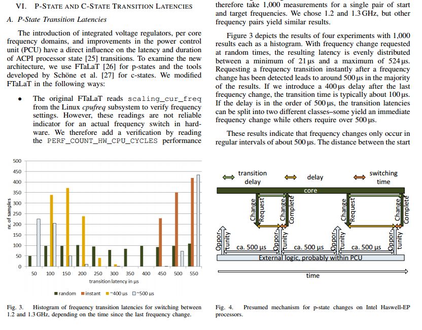
Intel On-chip Power Manager
 for Core Frequency [HSW,SKY]
 The HW power manager of Intel Architectures is quite slow in frequency variation!
 Literatures studied this mechanism and, for reverse engineering, discovered a 500us latency!

 *

 500us
* Intel Broadwell architectures as well!
Intel On-chip Power Manager
 for Uncore Frequency [SKY]
• Usually independently set, alternatively via MSR 0x620
• Manual: How long until takes affect ?
• Automatic: How long until detected ?
Intel On-chip Power Manager
 for Uncore Frequency [SKY]

 W1 Workload 2

funcore
 CPUs
 not
 avail.

 tcontrolloop tdelay tgap t
 tlatency
Intel On-chip Power Manager
 for Uncore Frequency [SKY]
 • Change frequency
 • While (time[current-1] not unexpected long)
 • time[current++]=timer(L3-bound
 workload)

 W1 Workload 2
 Outliers
funcore
 CPUs
 not
 avail.

 tcontrolloop tdelay tgap t
 tlatency
Intel On-chip Power Manager
 for Uncore Frequency [SKY]
 • Change frequency
 Up to 1.5 ms until
 • While (time[current-1] not unexpected long) frequency is changed when
 • time[current++]=timer(L3-bound triggered manually
 workload)

 W1 Workload 2

funcore
 CPUs
 not
 avail.

 tcontrolloop tdelay tgap t
 tlatency
Intel On-chip Power Manager
 for Uncore Frequency [SKY]
 • For (…)
 L1-bound workload Up to 11.5 ms until
 frequency is changed when
 • While (time[current-1] not unexpected long) triggered by internal
 • time[current++]=timer(L3-bound workload) mechanism

 W1 Workload 2

funcore
 CPUs
 not
 avail.

 tcontrolloop tdelay tgap t
 tlatency
Dynamic Duty Cycle Modulation
 DDCM (aka T-States)
Intel Xeon and Pentium M processors also support software-controlled clock modulation. DDCM was once known as T-
state (throttling state). This provides a means for operating systems to implement a power management policy to reduce
the power consumption and the temperature of the processor*. Power management software can write to the
IA32_CLOCK_MODULATION (0x19A) MSR to enable clock modulation and to select a modulation duty cycle.

*Bhalachandra, Sridutt, Allan Porterfield, and Jan F. Prins. "Using dynamic duty cycle modulation to improve energy efficiency in high performance computing." 2015 IEEE International
Parallel and Distributed Processing Symposium Workshop. IEEE, 2015.
Dynamic Duty Cycle Modulation
 DDCM (aka T-States)
• You might find papers that say, this works great, probably
 measured on Sandy Bridge processors
• On some systems (e.g., Sandy Bridge) DVFS is used, when all
 cores agree to a common T-State – that’s why it’s “great”
• On Haswell, Skylake:
 • Too many cycles skipped (compared to definition)
 • Highest T-state not available
• In short: Not worth it (only special circumstances, i.e.,
 processor without PCPs, slack-optimization)
• Source: [TState]
RAPL
HW Power Control - RAPL
 Intel architectures implement a hardware power controller called Running Average Power Limit (RAPL).

 Power Domains
 Package Domain: limits the power consumption for the
 entire package of the CPU, this includes cores and
 uncore components.

 DRAM Domain: is used to power cap the DRAM
 memory. It is available only for server architectures. (no
 client)

 PP0/Core Domain: is used to restrict the power limit
 DVFS
 only to the cores of the CPU (no new server).
 Time limiter
(typically from few ms PP1/Graphic Domain: is used to power limit only the
 to seconds) graphic component of the CPU (no server).
 Power limiter
 in Watts N.B. in the last slides of this presentation there
 (default TDP) is a complete description of RAPL registers
RAPL – Usage scenarios

• Hardware:
 • Measure power consumption for Turbo frequencies
 • Shift power budgets between cores and GPU
• Operating system/system vendors
 • Set given TDP
 • Monitor power consumption
• Users:
 • Monitor power consumption
RAPL – Mechanism

• Two power ranges:
 • Short term (typically 1 second?), typically exceeds TDP
 • Long term (typically 60 seconds?), typically TDP
• Processor must stay within both limits
• Internally sampled with typically (at least) 1 ms
• Processor can use free budgets for Turbo mechanisms
• Other facts:
 • Initially modelled, now measured
 • Also on AMD since Zen
Sysfs for RAPL

Sysfs Interface: /sys/devices/virtual/powercap/intel-rapl/intel-rapl:X/intel-rapl:0:Y
• X = number of package but this numbering does not reflect the package ID, this level contain the package
 domain information
• Y = 0 core domain, 1 gpu/uncore domain, 2 dram domain (the numbering can be different check the name)

• name: name of the domain and of the package ID
• max_energy_range_uj: range of the above energy counter in micro-joules
• energy_uj: current energy counter in micro joules
• enabled: enable/disable controls at domain level
• constraint_0_name: the name of the constraint 0 (usually long term window -> seconds)
• constraint_0_time_window_us: time window in micro seconds for the constraint 0
• constraint_0_power_limit_uw: power limit in micro watts for the constraint time 0
• constraint_0_max_power_uw: maximum allowed power in micro watts for the constraint 0
• constraint_1_name: the name of the constraint 1 (usually short term window -> milli seconds)
• constraint_1_time_window_us: time window in micro seconds for the constraint 0
• constraint_1_power_limit_uw: power limit in micro watts for the constraint time 1
• constraint_1_max_power_uw: maximum allowed power in micro watts for the constraint 0
Idle State (aka C-states)
Haswell ULP
Haswell EP Broadwell
 Skylake
Do not trust the last slide

• Check
 /sys/devices/system/cpu/cpuX/cpuidle/stateY
 to find out which (core) C-States your system supports
• This depends on:
 • Server or desktop or mobile
 • BIOS
 • Kernel
• Package C-state X are only used when all cores in the system
 (not only on one processor) are in core C-state X
• Otherwise, Package C2 can be used on the idling package
 (reduce latencies)
HLT & MWAIT Instructions

HLT (opcod F4):
• HLT is an assembly language instruction which halts the logical processor (clock gating) until the next
 external interrupt is fired.
• The HLT instruction is a privileged instruction, it requires ring 0 access, it can only be run by privileged
 system software such as the kernel (not in Xeon Phi!).
• The HLT instruction is executed by the operating system when there is no immediate work to be done, and
 the system enters its idle state (C1/C1E).

MWAIT (opcod 0F 01 C9):
• MWAIT is an assembly language instruction that provides hints to allow the processor to enter an
 implementation-dependent optimized state.
• MWAIT accepts a hint and optional extension to the processor that it can enter a specified target C state
 while waiting for an event.
• The MWAIT instruction can be executed only at privilege level 0.
C-State Transitions

Whenever OS sees idling period (more on that later), it will
1. Predict the length of the idle period
2. Choose a C-state based on proposed residency

 NOTE:
 • HLT or MWAIT instruction triggers the transition to lower power states.
 • Legacy method of I/O reads from the ACPI-defined processor clock control registers, referred to as P_LVLx.
 For legacy operating systems, P_LVLx I/O reads are converted within the processor to the equivalent
 MWAIT C-state request.
 • Interrupts (among others) triggers the transition to C0.
C-state Transition Times
 Haswell (EP) Broadwell Skylake
 Exit Exit Exit
 C-state Residency C-state Residency C-state Residency
 Latency Latency Latency
 C1 2 us 2 us C1 2 us 2 us C1 2 us 2 us

 C1E 10 us 20 us C1E 10 us 20 us C1E 10 us 20 us

 C3 33 us 100 us C3 40 us 100 us C3 70 us 100 us

 C6 133 us 400 us C6 133 us 400 us C6 85 us 200 us

 C7(s) 166 us 500 us C7(s) 166 us 500 us C7(s) 124 us 800 us

 C8 300 us 900 us C8 300 us 900 us C8 200 us 800 us

 C9 600 us 1800 us C9 600 us 1800 us C9 480 us 5000 us

 C10 2600 us 7700 us C10 2600 us 7700 us C10 890 us 5000 us
Note: information given by intel_idle kernel module (3.10 to 4.6 version) -> fake! This information are conservative, they are faster
[CSTATE,HSW,SKY]!
Transition times from CX to C0
 depend on
• Initial C-state
 • The lower the C-state, the higher the latency
• Frequency
 • Whether this has influence depends on the (Package) C-State
• How is the core waken up
 • From another core? Where is the other core?
 • By timer?
• Source:
 [CSTATE] Schöne, R., Molka, D., & Werner, M. (2015). Wake-up latencies for processor idle
 states on current x86 processors. Computer Science-Research and Development, 30(2), 219-
 227.
 [HSW,SKY]
Transition times from C0 to CX

• Entering a C-state can be delayed by hardware
• Waking up instantaneously after MWAIT can be fast

 Source:
 [LO2S-C] Ilsche, T., Schöne, R.,
 Joram, P., Bielert, M., & Gocht,
 A. (2018, May). System
 Monitoring with lo2s: Power
 and Runtime Impact of C-State
 Transitions. In 2018 IEEE
 International Parallel and
 Distributed Processing
 Symposium Workshops
 (IPDPSW) (pp. 712-715). IEEE.
OS Power Governor
acpi_cpufreq Governors
 • Performance: sets the CPU statically to the highest frequency
 • Powersave: sets the CPU statically to the lowest frequency
 • Userspace: allows the user, or any userspace program running with UID "root", to set the CPU to a
 specific frequency by making a sysfs file "scaling_setspeed" available in the CPU-device directory
 • Ondemand: sets the CPU depending on the current usage. To do this the CPU must have the
 capability to switch the frequency very quickly
 • Conservative: much like the "ondemand“ governor, sets the CPU depending on the current usage. It
 differs in behavior in that it gracefully increases and decreases the CPU speed rather than jumping to
 max speed the moment there is any load on the CPU
intel_pstate
 • Performance: always picks the highest frequency, race-to-halt machine or just don't care about
 energy, very similar to “performance” of cpufreq (only 1% faster)
 • Powersave: attempts to balance performance with energy savings is completely different than the
 cpufreq "powersave" governor. The strategy is similar to cpufreq "ondemand", where the requested
 P-State is related to the system load.

 N.B. In Intel CPU the default Linux driver is intel_pstate and the default governor is powersave!
OS Power Governor
 intel_pstate
• Active Mode With HWP: Start with HWP enable and cannot be disabled.
 • performance: intel_pstate will write 0 to the processor’s Energy-Performance Preference (EPP) knob (if supported) or its
 Energy-Performance Bias (EPB) knob (otherwise). This will override the EPP/EPB setting coming from the sysfs interface
 • powersave: intel_pstate will set the processor’s Energy-Performance Preference (EPP) knob (if supported) or its Energy-
 Performance Bias (EPB) knob (otherwise) to whatever value it was previously set to via sysfs (or whatever default value it was set
 to by the platform firmware). This usually causes the processor’s internal P-state selection logic to be less performance-focused.

• Active Mode Without HWP: This is the default operation mode for processors that do not support the HWP feature. It also is used by
 default with the intel_pstate=no_hwp argument in the kernel command line. However, in this mode intel_pstate may refuse to work
 with the given processor if it does not recognize it.
 • performance: It selects the maximum P-state it is allowed to use, subject to limits set via sysfs, every time the P-state selection
 computations are carried out by the driver’s utilization update callback for the given CPU (that does not happen more often
 than every 10 ms), but the hardware configuration will not be changed if the new P-state is the same as the current one.
 • powersave: It generally selects P-states proportional to the current CPU utilization, so it is referred to as the “proportional”
 algorithm.
• Passive Mode (also called intel_cpufreq): This mode is used if the intel_pstate=passive argument is passed to the
 kernel in the command line (it implies the intel_pstate=no_hwp setting too). Like in the active mode without HWP
 support, in this mode intel_pstate may refuse to work with the given processor if it does not recognize it. It implements
 the CPUFREQ interface.
Intel P-state driver: intel_pstate
 Sysfs Interface: /sys/devices/system/cpu/intel_pstate/*
 turbo_pct (%)
 Turbo enable
 Percentual: 0% min_perf_pct (%) max_perf_pct (%) = 100%
 Performance:
 P-state levels: 0 turbo_pstate num_pstates
 Turbo disable
 Percentual: 0% min_perf_pct (%) max_perf_pct (%) = 100%
 Performance:
 P-state levels: 0 turbo_pstate

 NOTE:
 • Any changes made to these files are applicable to all CPUs (even in a multi-package system).
 • In Intel p-state P0 the turbo boost take the responsibility to change the frequency with its own
 policy.
 • T-states existed to save processors from burning themselves up when things went very badly,
 such as when the cooling fan failed while the processor was running as fast as it could (use
 private temperature sensors).
Intel P-State Algorithm – PID control

 Error = 0
 PID adjustment
current cpu load Y current P-State
 + Error P + +
 - N +
 setpoint ∑ Error
Intel P-State – Userspace governor
Unfortunately, Intel P-state driver does not allow userspace governor! But intel_pstate driver is the default one on the
most HPC system based on Intel architecture.

So, we developed a hack which is able to inhibit the intel_pstate driver. You can find it in the school folder:
/gpfs/work/cin_powerdam_4/eeschool

What does the hack?
• Disable the turbo logic of intel_pstate driver
• Set the minimum frequency to the cpufreq interface of intel_pstate
• Set the maximum p-state using MSR
• Set the “energy performance bias hint” with the maximum performance value

How to run:
# Switch-off the intel_pstate
$> mpirun -n $SLURM_JOB_NUM_NODES -ppn 1 $WORK/eeschool/off_ipstate.sh

# Switch-on the intel_pstate
$> mpirun -n $SLURM_JOB_NUM_NODES -ppn 1 $WORK/eeschool/on_ipstate.sh
Idle governors

The Intel core C-states are requested by a power-aware kernel driver:

intel_idle: is a CPU idle driver that supports modern Intel processors. The intel_idle driver
presents the kernel with the duration of the target residency and exit latency for each
supported Intel processor. The CPU idle menu governor uses this data to predict how long
the CPU will be idle.

acpi_idle: implements the BIOS ACPI idle states. For this reason, it defines only four idle
states from C0 to C3 and it has no concept of core vs package C-states of Intel processors.
Moreover, it is inaccurate in C-state latencies and it has no concept of C-state energy
break-even.
Configuration of Idle States:
 intel_idle vs acpi_idle
Intel_idle driver uses knowledge of the various CPUs to control C-states without input from system firmware (BIOS).
If you want control over C-states, you should use kernel parameters:
intel_idle:
• intel_idle.max_cstate=0: this parameter disables the intel_idle, the Linux kernel will use the acpi_idle driver to use C-
 states. System firmware (BIOS) provides a list of available C-states to the operating system using an ACPI table.
• intel_idle.max_cstate=n: Limit the maximum depth of C-state from n = 1 to 9 to specify maximum depth of C-state.
• Disable C1e: C1e can be disabled in BIOS setup for low latency. When C1E is enabled, the processor will try to lower
 processor clock speed and voltage when it enters the C1 C-state, which might result in higher latency. From Linux kernel
 3.9, the intel_idle driver treats C1 and C1E as separate states. So, the user can control whether C1E is used without
 disabling it in BIOS setup.

acpi_idle (intel_idle disable):
• idle=poll: If a user wants the absolute minimum latency, kernel parameter “idle_poll” can be used to keep the processors
 in C0 even when they are idle (the processors will run in a loop when idle, constantly checking to see if they are needed).
 Hyperthreading should probably be disabled, as keeping processors in C0 can interfere with proper operation of logical
 cores. It can improve the performance but will use a lot of power and make the system run hot, not recommended.
• idle=halt: C-states can also be limited to C1 with the kernel parameter “idle=halt”.
• Idle=nomwait: Disable mwait instruction for CPU C-states
Dynamic control of C-States

To dynamically control C-states, open the file /dev/cpu_dma_latency and write the maximum allowable latency to it.
• This will prevent C-states with transition latencies higher than the specified value from being used, as long as the
 file /dev/cpu_dma_latency is kept open.

• cpu_dma_latency=0: Writing a maximum allowable latency of 0 will keep the processors in C0 (like using kernel
 parameter “idle=poll”)

• cpu_dma_latency=n: The value used should correspond to the latency values in
 /sys/devices/system/cpu/cpuX/cpuidle/stateY/latency (where X is the CPU number and Y is the idle state). This
 values corresponds to the transition time table in the previous slide.

• CPU idle states that have a greater latency than written to /dev/cpu_dma_latency should not be used.

Trick: One simple way to do this is by compiling a simple program that will write to this file, and stay open
until it is killed.

 N.B. avoiding CPU to enter in deep C-states limit the turbo frequency!!!
Sysfs for intel_idle (and acpi_idle)

Sysfs Interface: /sys/devices/system/cpu/cpuX/cpuidle/stateY -> Y = idle states are numbered (not level!)

• name: Name of the idle state (e.g. C1).
• desc: Description of the idle state (or the mwait code).
• latency: Exit latency of the idle state in microseconds.
• power: Power drawn by hardware in this idle state in milliwatts (if specified, 0 otherwise).
• residency: Target residency of the idle state in microseconds.
• time: Total time spent in this idle state by the given CPU (as measured by the kernel) in microseconds.
• usage: Total number of times the hardware has been asked by the given CPU to enter this idle state.
• above: Total number of times this idle state had been asked for, but the observed idle duration was
 certainly too short to match its target residency.
• below: Total number of times this idle state had been asked for, but certainly a deeper idle state would
 have been a better match for the observed idle duration.
• disable: Whether or not this idle state is disabled.
MSR & MSR_SAFE
What are MSRs?
A model-specific register (MSR) is any of various control registers in
the x86 instruction set used for debugging, program execution tracing,
computer performance monitoring, and toggling certain CPU features.

 Standard MSR linux driver
 Only root can access
Access to MSRs is Critical Processors provide low-level access to critical information and settings via MSRs Power: package (socket) and dram power Thermal: core, package in deg C Performance Counters: • Effective frequency • Instructions retired Enables studies on Advance performance measurements Power measurements Control for over-provisioned systems
Accessing MSR Data Special assembly instructions in kernel space (ring 0) rdmsr, wrmsr User level access through MSR kernel module Provides filesystem interface to all of the MSRs through /dev/cpu/X/msr No finer-grained permissions Access to MSR: rdmsr & wrmsr tool $> sudo modprobe msr $> sudo rdmsr -p -d -f : $> sudo wrmsr -p
Problem to solve No access/control for regular users in existing interfaces due to: Security Concerns • Full access to MSRs could allow you to “root” the machine • Pointer to the vector of hardware interrupt handlers is held in an MSR Permissions • All or nothing access Complexity in Registers • Error prone
Solution MSR_SAFE: kernel module developed by LLNL MSR kernel module + file permissions Only allow “trusted” users to have access with standard linux permissions Access through /dev/cpu/#/msr_safe msrmod: equivalent tool of rdmsr and wrmsr but it is based on MSR_SAFE driver Whitelist Bit level granularity Access to power, thermal, and performance counters/controls Formatted with tables to match Intel manuals (relatively easy to add new registers) Configuration through /dev/cpu/msr_whitelist https://github.com/LLNL/msr-safe
Example whitelist
Example whitelist permissions
Convenient access through Libmsr Companion library developed at LLNL Call high level library functions such as: • dump_thermal_terse() • dump_rapl_limit( … ) Build your own with easy to use: • Structs • Lower level functions https://github.com/LLNL/libmsr The library will do: • Error Checking • Low Level Work
Variorum: Vendor-neutral user space library for hardware control knobs Platform-agnostic simple front-facing APIs Variorum Security layer provided to ensure safe, developed by reliable operation Batching interfaces minimizing overheads of reading/writing many MSRs Production version of libmsr, which targeted Intel architectures C-based library Function pointers to specific Intel IBM NVIDIA implementation for target architecture RAPL OPAL NVML ARM AMD IBM+NVIDIA https://github.com/LLNL/variorum DVFS APM Power Shifting Ratio
References

• http://events.linuxfoundation.org/sites/events/files/slides/LinuxConEurope_2015.pdf

• https://www.kernel.org/doc/Documentation/cpu-freq/intel-pstate.txt

• https://people.cs.pitt.edu/~kirk/cs3150spring2010/ShiminChen.pptx

• Intel® 64 and IA-32 Architectures Software Developer’s Manual Combined Volumes:
 1, 2A, 2B, 2C, 3A, 3B, 3C and 3D

• Intel® Xeon Processor E5 and E7 v3 Family Uncore Performance Monitoring Reference
 Manual

• Source code of Linux kernel from 3.10 to 4.6 (www.kernel.org)
Follow-up
Running Average Power Limit
 RAPL
 RAPL interfaces provide mechanisms to enforce power consumption limit. RAPL interfaces consist of non-architectural
 MSRs. RAPL expose multiple domains (power planes) of power rationing within each processor socket. Each RAPL domain
 supports the following set of capabilities:
• Power limit - MSR interfaces to specify power limit, time window; lock bit,
 clamp bit etc.
• Energy Status - Power metering interface providing energy consumption
 information.
• Policy (Optional) - 4-bit priority information that is a hint to hardware for
 dividing budget between sub-domains in a parent domain.
• Perf Status (Optional) - Interface providing information on the performance
 effects (regression) due to power limits. It is defined as a duration metric that
 measures the power limit effect in the respective domain. The meaning of
 duration is domain specific.
• Power Info (Optional) - Interface providing information on the range of
 parameters for a given domain, minimum power, maximum power etc.

 Each of the above capabilities requires specific units in order to describe them. Power is expressed in
 Watts, Time is expressed in Seconds, and Energy is expressed in Joules. Scaling factors are supplied to each
 unit to make the information presented meaningful in a finite number of bits.
RAPL – Time Units and Domains
 Units for power, energy, and time are exposed in the read-only MSR_RAPL_POWER_UNIT (0x606) MSR.

 • Power Units (bits 3:0): Power related information (in Watts) is based on the multiplier, 1/2^PU; where PU is an unsigned integer
 represented by bits 3:0. Default value is 0011b, indicating power unit is in 1/8 Watts increment.
 • Energy Status Units (bits 12:8): Energy related information (in Joules) is based on the multiplier, 1/2^ESU; where ESU is an unsigned
 integer represented by bits 12:8. Default value is 10000b, indicating energy status unit is in 15.3 micro-Joules increment.
 • Time Units (bits 19:16): Time related information (in Seconds) is based on the multiplier, 1/2^TU; where TU is an unsigned integer
 represented by bits 19:16. Default value is 1010b, indicating time unit is in 976 microseconds increment.
 RAPL support the following RAPL domain hierarchy: entire package (PKG), DRAM, power plane for cores (PP0) and
 power plane for uncore graphic device (PP1). Each level of the RAPL hierarchy provides a respective set of RAPL interface
 MSRs.

NOTE: PP1 not present in server architectures
 DRAM present only in server architectures
RAPL – Package Domain
MSR_PKG_POWER_LIMIT allows a software agent to define power limitation for the package domain. MSR_PKG_POWER_INFO is a read-only MSR. It reports the package power range information for RAPL
Power limitation is defined in terms of average power usage (Watts) over a time window. Two power usage. This MSR provides maximum/minimum values (derived from electrical specification), thermal
limits can be specified, corresponding to time windows of different sizes. Each power limit provides specification power of the package domain. It also provides the largest possible time window for software to
independent clamping control that would permit the processor cores to go below OS-requested state to program the RAPL interface.
meet the power limits. A lock mechanism allow the software agent to enforce power limit settings. Once
the lock bit is set, the power limit settings are static and un-modifiable until next RESET. • Thermal Spec Power: The unsigned integer value is the equivalent of thermal specification power of the
 • Package Power Limit: Sets the average power usage limit of the package domain corresponding to package domain. The unit of this field is specified by the “Power Units” field of MSR_RAPL_POWER_UNIT.
 related time window. The unit of this field is specified by the “Power Units” field of • Minimum Power: The unsigned integer value is the equivalent of minimum power derived from electrical
 MSR_RAPL_POWER_UNIT spec of the package domain. The unit of this field is specified by the “Power Units” field of
 • Enable Power Limit: 0 = disabled; 1 = enabled MSR_RAPL_POWER_UNIT.
 • Package Clamping Limitation: Allow going below OS-requested P/T state setting during time • Maximum Power: The unsigned integer value is the equivalent of maximum power derived from the
 window. electrical spec of the package domain. The unit of this field is specified by the “Power Units” field of
 • Time Window for Power Limit: Indicates the time window for power limit. MSR_RAPL_POWER_UNIT.
 Time limit = 2^Y * (1.0 + Z/4.0) * Time Unit. • Maximum Time Window: The unsigned integer value is the equivalent of largest acceptable value to
 Here “Y” is the unsigned integer value represented by bits 21:17 – 53:49, “Z” is an unsigned integer program the time window of MSR_PKG_POWER_LIMIT. The unit of this field is specified by the “Time
 represented by bits 23:22 – 55:54. “Time Unit” is specified by the “Time Units” field of Units” field of MSR_RAPL_POWER_UNIT.
 MSR_RAPL_POWER_UNIT.
 • Lock: If set, all write attempts to this MSR are ignored until next RESET.

 MSR_PKG_PERF_STATUS is a read-only MSR. It reports the total time for which the package was throttled due
 to the RAPL power limits. Throttling in this context is defined as going below the OS-requested P-state or T-
 state. It has a wrap-around time of many hours.

MSR_PKG_ENERGY_STATUS is a read-only MSR. It reports the actual energy use for the package domain. • Accumulated Package Throttled Time: The unsigned integer value represents the cumulative time (since
This MSR is updated every ~1msec. It has a wraparound time of around 60 secs when power consumption the last time this register is cleared) that the package has throttled. The unit of this field is specified by
is high, and may be longer otherwise. the “Time Units” field of MSR_RAPL_POWER_UNIT.
• Total Energy Consumed: The unsigned integer value represents the total amount of energy consumed
 since that last time this register is cleared. The unit of this field is specified by the “Energy Status Units”
 field of MSR_RAPL_POWER_UNIT.
RAPL – PP0/PP1 Domain
MSR_PP0_POWER_LIMIT/MSR_PP1_POWER_LIMIT allow a software agent to define power limitation for MSR_PP0_POLICY/MSR_PP1_POLICY provide balance power policy control for each power plane by
the respective power plane domain. A lock mechanism in each power plane domain allows the software providing inputs to the power budgeting management algorithm. On platforms that support PP0 (IA cores)
agent to enforce power limit settings independently. Once a lock bit is set, the power limit settings in that and PP1 (uncore graphic device), the default values give priority to the non-IA power plane. These MSRs
power plane are static and un-modifiable until next RESET. enable the PCU to balance power consumption between the IA cores and uncore graphic device.
 • Power Limit: Sets the average power usage limit of the respective power plane domain. The unit of
 this field is specified by the “Power Units” field of MSR_RAPL_POWER_UNIT. • Priority Level: Priority level input to the PCU for respective power plane. PP0 covers the IA processor
 • Enable Power Limit: 0 = disabled; 1 = enabled. cores, PP1 covers the uncore graphic device. The value 31 is considered highest priority.
 • Clamping Limitation: Allow going below OS-requested P/T state setting during time window.
 • Time Window for Power Limit: Indicates the length of time window over which the power limit will
 be used by the processor. The numeric value encoded by bits 23:17 is represented by the product
 of 2^Y *F; where F is a single-digit decimal floating-point value between 1.0 and 1.3 with the
 fraction digit represented by bits 23:22, Y is an unsigned integer represented by bits 21:17. The unit
 of this field is specified by the “Time Units” field of MSR_RAPL_POWER_UNIT.
 • Lock: If set, all write attempts to the MSR and corresponding policy
 MSR_PP0_POLICY/MSR_PP1_POLICY are ignored until next RESET.

 MSR_PP0_PERF_STATUS is a read-only MSR. It reports the total time for which the PP0 domain was throttled
 due to the power limits. This MSR is supported only in server platform. Throttling in this context is defined as
 going below the OS-requested P-state or T-state.

 • Accumulated PP0 Throttled Time: The unsigned integer value represents the cumulative time (since the
 last time this register is cleared) that the PP0 domain has throttled. The unit of this field is specified by the
 “Time Units” field of MSR_RAPL_POWER_UNIT.

MSR_PP0_ENERGY_STATUS/MSR_PP1_ENERGY_STATUS are read-only MSRs. They report the actual
energy use for the respective power plane domains. These MSRs are updated every ~1msec.
• Total Energy Consumed: The unsigned integer value represents the total amount of energy
 consumed since the last time this register was cleared. The unit of this field is specified by the
 “Energy Status Units” field of MSR_RAPL_POWER_UNIT.
RAPL – DRAM Domain
MSR_DRAM_POWER_LIMIT allows a software agent to define power limitation for the DRAM domain. MSR_DRAM_POWER_INFO is a read-only MSR. It reports the DRAM power range information for RAPL
Power limitation is defined in terms of average power usage (Watts). A power limit can be specified along usage. This MSR provides maximum/minimum values (derived from electrical specification), thermal
with a time window. A lock mechanism allow the software agent to enforce power limit settings. Once the specification power of the DRAM domain. It also provides the largest possible time window for software to
lock bit is set, the power limit settings are static and un modifiable until next RESET. program the RAPL interface.

• DRAM Power Limit: Sets the average power usage limit of the DRAM domain corresponding to time
 • Thermal Spec Power: The unsigned integer value is the equivalent of thermal specification power of the
 window. The unit of this field is specified by the “Power Units” field of MSR_RAPL_POWER_UNIT.
 DRAM domain. The unit of this field is specified by the “Power Units” field of MSR_RAPL_POWER_UNIT.
• Enable Power Limit: 0 = disabled; 1 = enabled.
 • Minimum Power: The unsigned integer value is the equivalent of minimum power derived from electrical
• Time Window for Power Limit: Indicates the length of time window over which the power limit will
 spec of the DRAM domain. The unit of this field is specified by the “Power Units” field of
 be used by the processor. The numeric value encoded by bits 23:17 is represented by the product
 MSR_RAPL_POWER_UNIT.
 of 2^Y *F; where F is a single-digit decimal floating-point value between 1.0 and 1.3 with the
 • Maximum Power: The unsigned integer value is the equivalent of maximum power derived from the
 fraction digit represented by bits 23:22, Y is an unsigned integer represented by bits 21:17. The unit
 electrical spec of the DRAM domain. The unit of this field is specified by the “Power Units” field of
 of this field is specified by the “Time Units” field of MSR_RAPL_POWER_UNIT.
 MSR_RAPL_POWER_UNIT.
• Lock: If set, all write attempts to this MSR are ignored until next RESET.
 • Maximum Time Window: The unsigned integer value is the equivalent of largest acceptable value to
 program the time window of MSR_DRAM_POWER_LIMIT. The unit of this field is specified by the “Time
 Units” field of MSR_RAPL_POWER_UNIT.

MSR_DRAM_ENERGY_STATUS is a read-only MSR. It reports the actual energy use for the DRAM domain. MSR_DRAM_PERF_STATUS is a read-only MSR. It reports the total time for which the package was throttled
This MSR is updated every ~1msec. due to the RAPL power limits. Throttling in this context is defined as going below the OS-requested P-state or
 T-state. It has a wrap-around time of many hours.
• Total Energy Consumed: The unsigned integer value represents the total amount of energy
 consumed since that last time this register is cleared. The unit of this field is specified by the • Accumulated Package Throttled Time: The unsigned integer value represents the cumulative time (since
 “Energy Status Units” field of MSR_RAPL_POWER_UNIT. the last time this register is cleared) that the DRAM domain has throttled. The unit of this field is specified
 by the “Time Units” field of MSR_RAPL_POWER_UNIT.
You can also read