GNSS AND AVIONICS SIMULATION FOR ROHDE & SCHWARZ SIGNAL GENERATORS - Specifications
←
→
Page content transcription
If your browser does not render page correctly, please read the page content below
GNSS AND AVIONICS SIMULATION
FOR ROHDE & SCHWARZ
SIGNAL GENERATORS
Specifications
R&S®SMBV100B Vector Signal Generator
R&S®SMW200A Vector Signal Generator

Data Sheet
Version 10.00
Version 10.00, July 2020

CONTENTS
Definitions ....................................................................................................................................................................... 3
Overview .......................................................................................................................................................................... 4
    Abbreviations..................................................................................................................................................................................... 5

    GNSS testing with the R&S®SMW200A ............................................................................................................................................. 5

    Minimum instrument configuration for GNSS testing .......................................................................................................................... 6

    Minimum instrument configuration for avionics testing ....................................................................................................................... 6

Global navigation satellite systems (GNSS) ................................................................................................................. 7
    Addressed GNSS applications ........................................................................................................................................................... 7

    Signals and systems .......................................................................................................................................................................... 8

    Key features ...................................................................................................................................................................................... 9

    Common specifications for all GNSS options ................................................................................................................................... 10

    Specifications for GNSS options ...................................................................................................................................................... 13

    Channel allocation ........................................................................................................................................................................... 20

Avionics systems .......................................................................................................................................................... 23
    Key features .................................................................................................................................................................................... 23

    Specifications for avionics options ................................................................................................................................................... 23

Ordering information .................................................................................................................................................... 28
    R&S®SMBV100B ............................................................................................................................................................................. 28

    R&S®SMW200A .............................................................................................................................................................................. 29

2          Rohde & Schwarz GNSS and Avionics Simulation for Rohde & Schwarz Signal Generators
Version 10.00, July 2020
Definitions
General
Product data applies under the following conditions:
• Three hours storage at ambient temperature followed by 30 minutes warm-up operation
• Specified environmental conditions met
• Recommended calibration interval adhered to
• All internal automatic adjustments performed, if applicable
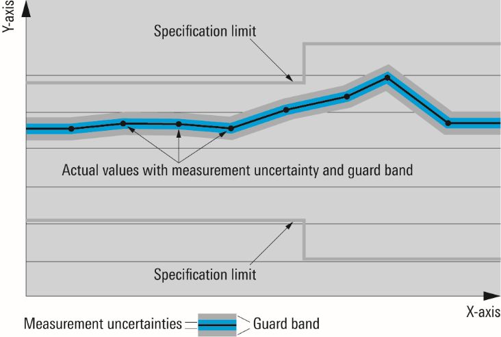
Specifications with limits
Represent warranted product performance by means of a range of values for the specified parameter. These specifications are
marked with limiting symbols such as , ≥, ±, or descriptions such as maximum, limit of, minimum. Compliance is ensured by
testing or is derived from the design. Test limits are narrowed by guard bands to take into account measurement uncertainties, drift
and aging, if applicable.
Non-traceable specifications with limits (n. trc.)
Represent product performance that is specified and tested as described under “Specifications with limits” above. However, product
performance in this case cannot be warranted due to the lack of measuring equipment traceable to national metrology standards. In
this case, measurements are referenced to standards used in the Rohde & Schwarz laboratories.
Specifications without limits
Represent warranted product performance for the specified parameter. These specifications are not specially marked and represent
values with no or negligible deviations from the given value (e.g. dimensions or resolution of a setting parameter). Compliance is
ensured by design.
Typical data (typ.)
Characterizes product performance by means of representative information for the given parameter. When marked with or as a
range, it represents the performance met by approximately 80 % of the instruments at production time. Otherwise, it represents the
mean value.
Nominal values (nom.)
Characterize product performance by means of a representative value for the given parameter (e.g. nominal impedance). In contrast to
typical data, a statistical evaluation does not take place and the parameter is not tested during production.
Measured values (meas.)
Characterize expected product performance by means of measurement results gained from individual samples.
Uncertainties
Represent limits of measurement uncertainty for a given measurand. Uncertainty is defined with a coverage factor of 2 and has been
calculated in line with the rules of the Guide to the Expression of Uncertainty in Measurement (GUM), taking into account
environmental conditions, aging, wear and tear.
Device settings and GUI parameters are designated with the format “parameter: value”.
Non-traceable specifications with limits, typical data as well as nominal and measured values are not warranted by Rohde & Schwarz.
In line with the 3GPP/3GPP2 standard, chip rates are specified in million chips per second (Mcps), whereas bit rates and symbol rates
are specified in billion bits per second (Gbps), million bits per second (Mbps), thousand bits per second (kbps), million symbols per
second (Msps) or thousand symbols per second (ksps), and sample rates are specified in million samples per second (Msample/s).
Gbps, Mcps, Mbps, Msps, kbps, ksps and Msample/s are not SI units.
Rohde & Schwarz GNSS and Avionics Simulation for Rohde & Schwarz Signal Generators 3Version 10.00, July 2020
Overview
With the GNSS and avionics simulation solutions for the R&S®SMBV100B and the R&S®SMW200A, dynamic scenarios with
GPS/SBAS/QZSS, Galileo, GLONASS and BeiDou signals can be generated in real-time including moving scenarios, multipath,
dynamic power control and atmospheric modeling. For moving scenarios, the effects of antenna pattern and vehicle body mask can be
simulated in real-time with dynamic variation of the vehicle’s attitude. Above and beyond GNSS signal generation, the
R&S®SMBV100B and the R&S®SMW200A are flexible vector signal generators with excellent RF performance. They offer options for
generating standard-compliant signals for all important digital communications standards (GSM, WCDMA, HSPA+, LTE, WiMAXTM,
WLAN, etc.). This versatility allows mobile phone or car infotainment system manufacturers that integrate GNSS modules into their
products to test the GNSS functionality and the normal functionality of their products with only one instrument.
This document contains the functional specifications of the GNSS-related software options for the R&S®SMBV100B and the
R&S®SMW200A:
Option R&S®SMBV100B R&S®SMW200A
GNSS
GPS R&S®SMBVB-K44 R&S®SMW-K44
Modernized GPS R&S®SMBVB-K98 R&S®SMW-K98
Galileo R&S®SMBVB-K66 R&S®SMW-K66
GLONASS R&S®SMBVB-K94 R&S®SMW-K94
BeiDou R&S®SMBVB-K107 R&S®SMW-K107
Modernized BeiDou R&S®SMBVB-K132 R&S®SMW-K132
SBAS/QZSS R&S®SMBVB-K106 R&S®SMW-K106
Real world scenarios R&S®SMBVB-K108 R&S®SMW-K108
Real-time GNSS interfaces R&S®SMBVB-K109 R&S®SMW-K109
Single-satellite GNSS R&S®SMBVB-K133 –
Upgrade to dual-frequency GNSS R&S®SMBVB-K134 R&S®SMW-K134
Upgrade to triple-frequency GNSS R&S®SMBVB-K135 R&S®SMW-K135
Add 6 GNSS channels R&S®SMBVB-K136 R&S®SMW-K136
Add 12 GNSS channels R&S®SMBVB-K137 R&S®SMW-K137
Add 24 GNSS channels – R&S®SMW-K138
Add 48 GNSS channels – R&S®SMW-K139
ERA-GLONASS test suite R&S®SMBVB-K360 R&S®SMW-K360
eCall test suite R&S®SMBVB-K361 R&S®SMW-K361
Extension to 48 GNSS channels per – R&S®SMW-K99
baseband (in combination with
R&S®SMW-B10(F))
Advanced GNSS applications (in – R&S®SMW-K120
combination with R&S®SMW-B10)
Avionics
GBAS R&S®SMBVB-K111 –
ILS R&S®SMBVB-K151 –
VOR R&S®SMBVB-K152 –
DME R&S®SMBVB-K153 –
For information on other digital standards or signal quality such as phase noise or spurious,
see the following Rohde & Schwarz documents:
• R&S®SMBV100B data sheet, PD 3607.8201.22
• R&S®SMBV100B product brochure, PD 3607.8201.12
• R&S®SMW200A data sheet, PD 5214.1114.22
• R&S®SMW200A product brochure, PD 5214.1114.12
• Digital standards for signal generators data sheet, PD 5213.9434.22
4 Rohde & Schwarz GNSS and Avionics Simulation for Rohde & Schwarz Signal GeneratorsVersion 10.00, July 2020
Abbreviations
The following abbreviations are used in this document:
• The R&S®SMBVB-K44 and the R&S®SMW-K44 are referred to as K44
• The R&S®SMBVB-K98 and the R&S®SMW-K98 are referred to as K98
• The R&S®SMBVB-K66 and the R&S®SMW-K66 are referred to as K66
• The R&S®SMBVB-K94 and the R&S®SMW-K94 are referred to as K94
• The R&S®SMBVB-K107 and the R&S®SMW-K107 are referred to as K107
• The R&S®SMBVB-K132 and the R&S®SMW-K132 are referred to as K132
• The R&S®SMBVB-K106 and the R&S®SMW-K106 are referred to as K106
• The R&S®SMBVB-K99 and the R&S®SMW-K99 are referred to as K99
• The R&S®SMBVB-K108 and the R&S®SMW-K108 are referred to as K108
• The R&S®SMBVB-K109 and the R&S®SMW-K109 are referred to as K109
• The R&S®SMBVB-K133 is referred to as K133
• The R&S®SMBVB-K134 and the R&S®SMW-K134 are referred to as K134
• The R&S®SMBVB-K135 and the R&S®SMW-K135 are referred to as K135
• The R&S®SMBVB-K136 and the R&S®SMW-K136 are referred to as K136
• The R&S®SMBVB-K137 and the R&S®SMW-K137 are referred to as K137
• The R&S®SMW-K138 is referred to as K138
• The R&S®SMW-K139 is referred to as K139
• The R&S®SMBVB-K360 and the R&S®SMW-K360 are referred to as K360
• The R&S®SMBVB-K361 and the R&S®SMW-K361 are referred to as K361
• The R&S®SMBVB-K111 is referred to as K111
• The R&S®SMBVB-K151 is referred to as K151
• The R&S®SMBVB-K152 is referred to as K152
• The R&S®SMBVB-K153 is referred to as K153
• The R&S®SMW-K120 is referred to as K120
• The R&S®SMW-B9 is referred to as B9
• The R&S®SMW-B10 is referred to as B10
• The R&S®SMW-B10(F) is referred to as B10(F)
• The R&S®SMW-B13 is referred to as B13
• The R&S®SMW-B15 is referred to as B15
GNSS testing with the R&S®SMW200A
The R&S®SMW200A can be equipped with 2 different types of baseband hardware. When equipped with B10 baseband generators,
the maximum RF bandwidth is limited to 160 MHz which prevents the baseband from simultaneously generating GNSS signals from
different GNSS frequency bands. This limitation can be overcome by using an B9 baseband generator. Being able to support a
maximum RF bandwidth of 2 GHz, multi-frequency GNSS signals can be simulated out of one single baseband module. Compared to
the B10 baseband module, the B9 also allows to simulate more GNSS channels and the number of channels can even be increased
further by adding GNSS coder boards (2 × B15 or 4 × B15). The following table contains a comparison of some important GNSS
simulation features when using different instrument configurations:
Configuration with 2 × R&S®SMW-B9
with R&S®SMW-B10 with R&S®SMW-B9
Feature and 4 × R&S®SMW-B15
Maximum number of channels per
144 204 612
R&S®SMW200A
Maximum number of channels per baseband 48 102 102
Multi-frequency GNSS on one baseband no yes yes
4 (with 2 × signal
RF out 2 2
generator)
In addition to these different simulation capabilities, the type of baseband hardware being used in the R&S®SMW200A also determines
which software options can be installed on the instrument. The following table lists all GNSS options that can be installed on an
instrument equipped with a B10 or B9 baseband, module:
Option Available in Available in
combination with combination with
R&S®SMW-B9 R&S®SMW-B10(F)
GPS R&S®SMW-K44 ● ●
Modernized GPS R&S®SMW-K98 ● ●
Galileo R&S®SMW-K66 ● ●
GLONASS R&S®SMW-K94 ● ●
BeiDou R&S®SMW-K107 ● ●
Modernized BeiDou R&S®SMW-K132 ● ●
SBAS/QZSS R&S®SMW-K106 ● ●
Real world scenarios R&S®SMW-K108 ● ●
Rohde & Schwarz GNSS and Avionics Simulation for Rohde & Schwarz Signal Generators 5Version 10.00, July 2020
Real-time GNSS interfaces R&S®SMW-K109 ● ●
Upgrade to dual-frequency GNSS R&S®SMW-K134 ● –
Upgrade to triple-frequency GNSS R&S®SMW-K135 ● –
Add 6 GNSS channels R&S®SMW-K136 ● –
Add 12 GNSS channels R&S®SMW-K137 ● –
Add 24 GNSS channels R&S®SMW-K138 ● –
Add 48 GNSS channels R&S®SMW-K139 ● –
ERA-GLONASS test suite R&S®SMW-K360 ● ●
eCall test suite R&S®SMW-K361 ● ●
Extension to 48 GNSS channels per R&S®SMW-K99 – ●
baseband
(in combination with R&S®SMW-B10(F))
Advanced GNSS applications R&S®SMW-K120 – ●
(in combination with R&S®SMW-B10)
Minimum instrument configuration for GNSS testing
The following minimum hardware configuration is required as a prerequisite for testing GNSS functionality.
Required options for R&S®SMBV100B
R&S®SMBV100B base unit incl. BB generator with ARB (64 Msample,
120 MHz RF bandwidth)
R&S®SMBVB-B103 frequency option, 8 kHz to 3 GHz
R&S®SMBVB-K520 real-time extension
Required options for R&S®SMW200A
R&S®SMW200A base unit
R&S®SMW-B1003 frequency option, RF path A, 100 kHz to 3 GHz
R&S®SMW-B13 signal routing and baseband main module, one I/Q path to RF
R&S®SMW-B10 baseband generator with ARB (64 Msample) and
real-time coder, 120 MHz RF bandwidth
Minimum instrument configuration for avionics testing
The following minimum hardware configuration is required as a prerequisite for installing avionics options.
Required options for R&S®SMBV100B
R&S®SMBV100B base unit incl. BB generator with ARB (64 Msample,
120 MHz RF bandwidth)
R&S®SMBVB-B103 frequency option, 8 kHz to 3 GHz
R&S®SMBVB-K520 real-time extension
6 Rohde & Schwarz GNSS and Avionics Simulation for Rohde & Schwarz Signal GeneratorsVersion 10.00, July 2020
Global navigation satellite systems (GNSS)
Addressed GNSS applications
The main difference between the R&S®SMBV100B and the R&S®SMW200A in terms of GNSS testing is that the R&S®SMBV100B has
one single RF output whereas the R&S®SMW200A can be equipped with two or even up to four RF outputs (with additional signal
generators). That way, both instruments are able to address different types of GNSS test applications, which are summarized in the
following tables:
Midrange GNSS applications with R&S®SMBV100B
Frequency bands Applications Test
L1, L2 and L5 single and multi-frequency applications • GNSS production testing
• standard receiver tests for receiver
characterization
• standard receiver tests under special
conditions (interference, multipath,
leap seconds)
• RAIM testing
High-end GNSS applications with R&S®SMW200A
Frequency bands Applications Test
L1, L2 and L5 single and multi-frequency applications • standard receiver tests for receiver
characterization
• standard receiver tests under special
conditions (interference, multipath,
leap seconds)
• RAIM testing
• ionospheric monitoring
• atmospheric sounding
multi-antenna applications • baseline determination
• beamforming (CRPA)
• attitude determination
• multipath direction finding
multi-vehicle applications • differential GNSS
• collision avoidance
• spacecraft formation flying
• time and frequency transfer
advanced interference simulation • simulating of jamming/spoofing attacks
• coexistence testing with several
interferers
Rohde & Schwarz GNSS and Avionics Simulation for Rohde & Schwarz Signal Generators 7Version 10.00, July 2020
Signals and systems
System Frequency Supported Required options for Required options for
band signals R&S®SMBV100B R&S®SMW200A
GNSS GPS L1 C/A code, R&S®SMBVB-K44 R&S®SMW-K44
P code
L2 C/A code, R&S®SMBVB-K44 R&S®SMW-K44
P code
L2 L2C R&S®SMBVB-K98 R&S®SMW-K98
L5 L5 R&S®SMBVB-K98 R&S®SMW-K98
GLONASS L1 C/A code R&S®SMBVB-K94 R&S®SMW-K94
L2 C/A code R&S®SMBVB-K94 R&S®SMW-K94
Galileo E1 OS data/pilot R&S®SMBVB-K66 R&S®SMW-K66
E5 E5a data/pilot R&S®SMBVB-K66 R&S®SMW-K66
E5b data/pilot
E6 E6 data/pilot R&S®SMBVB-K66 R&S®SMW-K66
BeiDou B1 B1-I R&S®SMBVB-K107 R&S®SMW-K107
B2 B2-I R&S®SMBVB-K107 R&S®SMW-K107
B1 B1C R&S®SMBVB-K132 R&S®SMM-K132
B2 B2a R&S®SMBVB-K132 R&S®SMM-K132
B3 B3-I R&S®SMBVB-K132 R&S®SMM-K132
SBAS QZSS L1 C/A code R&S®SMBVB-K106 R&S®SMW-K106
WAAS L1 C/A code R&S®SMBVB-K106 R&S®SMW-K106
EGNOS L1 C/A code R&S®SMBVB-K106 R&S®SMW-K106
MSAS L1 C/A code R&S®SMBVB-K106 R&S®SMW-K106
GAGAN L1 C/A code R&S®SMBVB-K106 R&S®SMW-K106
In the R&S®SMBV100B and the R&S®SMW200A, the designators L1, L2 and L5 are used when referring to a specific GNSS
frequency band. The following table shows how the supported signals are mapped to these bands.
L1 L2 L5
GPS C/A, P C/A, P, L2C L5
Galileo E1 OS E6 E5a, E5b
GLONASS C/A C/A –
BeiDou B1I, B1C B3I B2I, B2a
SBAS C/A – –
QZSS C/A – –
8 Rohde & Schwarz GNSS and Avionics Simulation for Rohde & Schwarz Signal GeneratorsVersion 10.00, July 2020
Key features
GNSS features (independent from instrument type)
• Support of all global satellite navigation systems (GPS, GLONASS, Galileo, BeiDou)
• Support of satellite-based augmentation systems (SBAS)
• Static and dynamic GNSS scenarios
• Moving receiver simulations based on predefined and user-defined waypoints with additional support of NMEA and KML files and
waypoint smoothing using vehicle description files
• Support of A-GNSS test scenarios, including generation of A-GNSS assistance data
• Realistic GNSS scenarios with consideration of
− Orbit perturbations and clock errors
− Tropospheric and ionospheric effects
− Signal obscuration and multipath
− Antenna gain and phase patterns
− User trajectories with consideration of vehicle attitude
− Pseudorange steps and ramps for RAIM testing
• Interactive power control of individual satellites
• Optional internal noise generator
• Integrated GNSS simulation software with user-friendly simulation configuration, monitoring and interactive control capabilities
using the instrument’s large touchscreen
• Logging of user motion and satellite-related parameters
• Scenario generation can be fully automated using extensive remote control capabilities via Ethernet, USB or GPIB
• Automatic GNSS performance testing for ERA-GLONASS modules against GOST-R-55534/33471 performance criteria
• Automatic GNSS performance testing for eCall modules against EU2017/79 Annex VI and UNECE2016/07 performance criteria
• Hardware-in-the-loop (HIL) real-time feed of vehicle’s motion and attitude data (position, velocity, acceleration and jerk)
GNSS features (related to instrument type)
Feature R&S®SMBV100B R&S®SMW200A
Multi-frequency scenarios yes yes
GNSS frequency bands L1, L2 and L5 L1, L2 and L5
Number of GNSS channels 6 to 102 24 to 612
Number of RF outputs 1 1 to 4
Maximum number of simulated antennas 1 4
Maximum number of simulated vehicles 1 2
Measured worst case pseudorange < 1 cm < 1 cm
accuracy
Hardware update rate 100 Hz 100 Hz
Signal dynamics
Velocity max. 600 m/s max. 10000 m/s
Acceleration max. 1600 m/s² max. 1600 m/s²
Jerk max. 400 m/s³ max. 400 m/s³
HIL streaming rate 100 Hz 100 Hz
HIL latency 20 ms 20 ms
Interference generation yes yes
Interference sources 1 7
Interference scenarios GNSS + CW interference or • GNSS + CW interference
GNSS + AWGN • GNSS + AWGN
• GNSS + comm. signal (coexistence)
• GNSS + jamming
• spoofing
Rohde & Schwarz GNSS and Avionics Simulation for Rohde & Schwarz Signal Generators 9Version 10.00, July 2020
Common specifications for all GNSS options
Simulation configuration
R&S®SMBV100B R&S®SMW200A
Simulation time flexible date and time (UTC) or resolution of 1 ms
GNSS system time configuration
leap second simulation
Simulation modes/test tracking signal generation with constant or custom Doppler profiles
modes for individual satellites
Single-satellite per system simulation of one single- –
satellite for the following
systems: GPS, Glonass,
Galileo, BeiDou
Coordinate systems for configuring static locations or user trajectories (ECEF WGS84 PZ-90.11)
altitude –10 000 m to +50 000 000 m in steps of 0.1 m
latitude –90° to +90° in steps of 0.000001°
longitude –180° to +180° in steps of 0.000001°
Trajectory configuration waypoint files with multiple formats XTD (proprietary trajectory format, see user manual for
format description), KML, NMEA formats
possibility to smooth the trajectory
depending on vehicle dynamics
Constellation configuration default constellations available that
and navigation data sources will be internally extrapolated for
different simulation start times
data can be imported from multiple RINEX, YUMA, SEM, AGL, XML
publicly available file formats
Channel selection criteria satellite visibility time • automatic exchange of invisible satellites with visible
ones, with preference to those with longest visibility
duration at the current position
• visible satellites can be turned on/off without interrupting
the simulation
satellite elevation same as above, with preference on satellites of higher
elevation
manual satellites can be arbitrarily turned on/off without any
automatic exchange
Elevation mask earth tangent, excludes satellites below a specific elevation;
local horizon range: –10° to 90°
Tropospheric models none possibility of removing troposphere errors
STANAG STANAG Doc. 4294
MOPS 229D minimum operational performance standard for
GPS/SBAS airborne equipment
Ionospheric models none possibility of removing ionosphere errors
STANAG STANAG Doc. 4294
NeQuick NeQuick ionosphere model
MOPS 229D minimum operational performance standard for
GPS/SBAS airborne equipment
Satellite vehicle parameters state switch satellites on/off,
modifiable on-the-fly
10 Rohde & Schwarz GNSS and Avionics Simulation for Rohde & Schwarz Signal GeneratorsVersion 10.00, July 2020
Power configuration reference power received power per signal assuming all offsets are zero
(setting range: –145 dBm to –20 dBm)
satellite vehicle power offset attenuation for all signals transmitted from a single-satellite,
modifiable on-the-fly
free space path-loss automatically calculated attenuation due to the line-of-sight
distance between transmit and receive antenna
signal power offset additional attenuation of a specific signal (–21 dB to 0 dB,
updated in real-time without restarting the simulation)
pseudorange errors
in navigation mode • constant bias, modifiable on-the-fly
• profile (steps, ramps): suitable for testing receiver
autonomous integrity monitoring (RAIM)
• synchronized with corrections broadcasted in SBAS:
The ionosphere errors will match the MOPS grid
broadcasted by SBAS. Moreover, for GPS satellite, the
deviation between the simulated orbits and clock and
those broadcasted by the satellites will match the
amount of differential correction broadcasted in SBAS
message about the individual GPS space vehicles.
constant signal dynamics
in tracking mode • pseudorange (0 to 119900 km)
• pseudorange rate (–100 km/s to 100 km/s)
• carrier Doppler is coupled with pseudorange rate
• initial carrier phase: 0 to 2π rad
high-order signal dynamics
in tracking mode periodic profiles with acceleration, constant velocity and
deceleration
Connectivity marker • 1 PPS
• 1 PP2S
• 10 PPS
• pulse
• pattern
• on/off ratio
• trigger
triggering see R&S®SMBV100B see R&S®SMW200A
data sheet, section: data sheet, section:
I/Q baseband generator I/Q baseband generator
Rohde & Schwarz GNSS and Avionics Simulation for Rohde & Schwarz Signal Generators 11Version 10.00, July 2020
Simulation monitoring
Available in test mode R&S®SMBV100B R&S®SMW200A
Sky view navigation shows the distribution of GNSS satellites in the sky
Power view navigation and tracking bar plot visualizing the signals’ power levels
Satellite vehicle trajectory navigation azimuth/elevation of individual space vehicles over 24 h
relative to simulation start
World map navigation shows the simulated user position on a world map
Map view navigation shows the currently simulated user position along with a
preview of the full trajectory
Vehicle dynamics navigation visualizes position, velocity and attitude information
(heading, elevation and bank) in the form of an artificial
horizon
Hardware channels view navigation and tracking visualizes the assignment of each GNSS signal in the
hardware channels and its corresponding power (in dBm),
each signal represents a unique combination of:
vehicle/antenna/band/multipath-ray/signal type
Simulation data logging
R&S®SMBV100B R&S®SMW200A
Logging mode real-time log, offline log • logs simulation data during the currently running
simulation
• simulation run is performed as fast as possible without
producing an RF signal for fast generation of logging
data
Log types satellite data • elapsed time, UTC date and time,
system/SVID, elevation, azimuth,
ECEF XYZ position (in m),
ECEF XYZ velocity (in m/s),
ECEF XYZ acceleration in (in m/s2),
clock bias (in m)
• signal level (in dBm)
• range, pseudorange (in m)
• range, pseudorange rates (in m/s)
• pseudorange bias (in m)
• pseudorange bias rate (in m/s)
• Doppler shift (in Hz)
• carrier phase (in deg)
• tropospheric, ionospheric delays (in m)
vehicle motion • elapsed time, UTC date and time
• latitude (in deg)
• longitude (in deg)
• altitude (in m)
• position XYZ (in m)
• velocity XYZ (in m/s)
• acceleration XYZ (in m/s2)
• jerk XYZ (in m/s3)
• position east, north, upper (in m)
• velocity east, north, upper (in m/s)
• ground speed (in m/s)
• attitude rate yaw, pitch, roll (in deg)
• attitude rate yaw, pitch, roll (in deg/s)
• attitude acceleration yaw, pitch, roll (in deg/s2)
• attitude jerk yaw, pitch, roll (in deg/s3)
• GDOP, PDOP, HDOP, VDOP, TDOP
• visible space vehicles
12 Rohde & Schwarz GNSS and Avionics Simulation for Rohde & Schwarz Signal GeneratorsVersion 10.00, July 2020
Specifications for GNSS options
GPS (R&S®SMBVB/SMW-K44 option)
Can be installed once on the R&S®SMBV100B and twice on the R&S®SMW200A.
R&S®SMBV100B R&S®SMW200A
GPS in line with ICD-GPS-200 revision H
Simulation configuration, see section Common specifications for all GNSS options
monitoring, logging
Channel budget see section Channel allocation
Frequency bands L1, L2 L1, L2
Center frequencies 1575.42 MHz, 1227.60 MHz 1575.42 MHz, 1227.60 MHz
Signals C/A code, P code C/A code, P code
Maximum number of SVs 6 (can be extended with 24 (37 with K99)
K136/K137)
Navigation data format LNAV
Space vehicles PRNs 1 to 37
Modernized GPS (R&S®SMBVB/SMW-K98 option)
Can be installed once on the R&S®SMBV100B and twice on the R&S®SMW200A.
R&S®SMBV100B R&S®SMW200A
GPS in line with ICD-GPS-200 revision H and ICD-GPS-705
revision E
Simulation configuration, see section Common specifications for all GNSS options
monitoring, logging
Channel budget see section Channel allocation
Frequency bands L2, L5 L2, L5
Center frequencies 1227.60 MHz, 1176.45 MHz 1227.60 MHz, 1176.45 MHz
Signals L2C, L5 L2C, L5
Number of GNSS channels 6 24
Channel extension options K136/K137 K136/K137/K138/K139
(in combination with B9),
K99 (in combination with
B10)
Navigation data format LNAV, data list, pattern, All0, All1, PRBS
Space vehicles PRNs 1 to 37
Galileo (R&S®SMBVB/SMW-K66 option)
Can be installed once on the R&S®SMBV100B and twice on the R&S®SMW200A.
R&S®SMBV100B R&S®SMW200A
Galileo in line with OS SIS ICD, in line with OS SIS ICD,
E1 band E1/E5 band
Simulation configuration, see section Common specifications for all GNSS options
monitoring, logging
Channel budget see section Channel allocation
Frequency bands E1, E5, E6 E1, E5, E6
Center frequencies 1575.42 MHz, 1575.42 MHz,
1191.795 MHz, 1191.795 MHz,
1278.75 MHz 1278.75 MHz
Signals E1 open service, E5a, E5b E1 open service, E5a, E5b
Number of GNSS channels 6 24
Channel extension options K136/K137 K136/K137/K138/K139
(in combination with B9),
K99 (in combination with
B10)
Navigation data format I/NAV for E1/E5b, F/NAV for E5a, data list, pattern, All0,
All1, PRBS
Space vehicles PRNs 1 to 30
Rohde & Schwarz GNSS and Avionics Simulation for Rohde & Schwarz Signal Generators 13Version 10.00, July 2020
GLONASS (R&S®SMBVB/SMW-K94 option)
Can be installed once on the R&S®SMBV100B and twice on the R&S®SMW200A.
R&S®SMBV100B R&S®SMW200A
GLONASS in line with GLONASS ICD version 5.0
Simulation configuration, see section Common specifications for all GNSS options
monitoring, logging
Channel budget see section Channel allocation
Frequency bands L1, L2 L1, L2
Center frequencies 1602.0 MHz, 1246.0 MHz 1602.0 MHz, 1246.0 MHz
Signals C/A code C/A code
Number of GNSS channels 6 24
Channel extension options K136/K137 K136/K137/K138/K139
(in combination with B9),
K99 (in combination with
B10)
Navigation data format GLONASS NAV, data list, pattern, All0, All1, PRBS
Space vehicles PRNs 1 to 24
BeiDou (R&S®SMBVB/SMW-K107 option)
Can be installed once on the R&S®SMBV100B and twice on the R&S®SMW200A.
R&S®SMBV100B R&S®SMW200A
BeiDou in line with BDS-SIS-ICD-BI-2.0
Simulation configuration, see section Common specifications for all GNSS options
monitoring, logging
Channel budget see section Channel allocation
Frequency bands B1, B2 B1, B2
Center frequencies 1561.098 MHz, 1561.098 MHz,
207.140 MHz 207.140 MHz
Orbits GSO, IGSO, MEO
Signals B1 I (GSO), B1 I (Non-GSO),
B2 I (GSO), B2 I (Non-GSO),
Number of GNSS channels 6 24
Channel extension options K136/K137 K136/K137/K138/K139
(in combination with B9),
K99 (in combination with
B10)
Navigation data format D1 NAV, D2 NAV, data list, pattern, All0, All1, PRBS
Space vehicles PRNs 1 to 35
Modernized BeiDou (R&S®SMBVB/SMW-K132 option)
Can be installed once on the R&S®SMBV100B and twice on the R&S®SMW200A.
R&S®SMBV100B R&S®SMW200A
BeiDou in line with BDS-SIS-ICD-B3I-1.0, BDS-SIS-ICD-B2a-1.0,
BDS-SIS-ICD-B1C-1.0
Simulation configuration, see section Common specifications for all GNSS options
monitoring, logging
Channel budget see section Channel allocation
Frequency bands B1, B2, B3 B1, B2, B3
Center frequencies 1176.45 MHz, 1268.52 MHz, 1176.45 MHz, 1268.52 MHz,
1575.42 MHz 1575.42 MHz
Signals B1C, B2a, B3I (GSO, B1C, B2a, B3I (GSO,
Non-GSO) Non-GSO)
Number of GNSS channels 6 24
Channel extension options K136/K137 K136/K137/K138/K139
(in combination with B9),
K99 (in combination with
B10)
Navigation data format CNAV, D1 NAV, D2 NAV, data list, pattern, All0, All1, PRBS
Space vehicles PRNs 1 to 35
14 Rohde & Schwarz GNSS and Avionics Simulation for Rohde & Schwarz Signal GeneratorsVersion 10.00, July 2020
SBAS/QZSS (R&S®SMBVB/SMW-K106 option)
Requires the R&S®SMBVB/SMW-K44 option. Can be installed once on the R&S®SMBV100B and twice on the R&S®SMW200A.
R&S®SMBV100B R&S®SMW200A
SBAS in line with:
DO-229D, minimum operational performance standard for
global positioning system/wide area augmentation system
airborne equipment
Simulation configuration, see section Common specifications for all GNSS options
monitoring, logging
Channel budget see section Channel allocation
Frequency bands L1 L1
Center frequencies 1547.42 MHz 1547.42 MHz
Signals C/A code C/A code
Number of GNSS channels 5 5
Navigation data format SBAS-L1-NAV, data list, pattern, All0, All1, PRBS
Regional systems • WAAS
• EGNOS
• MSAS
• GAGAN
Space vehicles PRN: 120, 124, 126, 131, 136, 122, 133, 134, 135, 138,
129, 137
Differential corrections automatically generated The broadcasted corrections reflect the simulated errors in
the GNSS constellation: ionosphere model, pseudorange
error, orbit and clock deviations.
replay of historical data with loading of downloaded daily data from
possibility to edit EGNOS and WAAS FTP servers:
EGNOS message server EMS format and WAAS real-time
data NSTB format.
MSAS and GAGAN raw data are not supported. Optionally
the ionosphere model pseudo-range error GPS satellite can
be synchronized to the imported data.
Message types • almanac • MT 17
• ephemeris • MT 9
• time conversion to UTC • MT 12
• ionosphere corrections • MT 18 and 26
• PRN mask • MT 1
• fast corrections • MT 2, 3, 4, 5, 6 and 24
• long-term corrections • MT 25 and 24
• degradation parameters • MT 7 and 10
• clock and ephemeris covariance • MT 28
matrix
R&S®SMBV100B R&S®SMW200A
QZSS in line with IS-QZSS V1.6
Simulation configuration, see section Common specifications for all GNSS options
monitoring, logging
Channel budget see section Channel allocation
Frequency bands L1 L1
Center frequencies 1547.42 MHz 1547.42 MHz
Signals C/A code C/A code
Number of GNSS channels 5 5
Navigation data format QZSS-L1-NAV, data list, pattern, All0, All1, PRBS
Space vehicles PRN: 193, 194, 195, 196, 197
Rohde & Schwarz GNSS and Avionics Simulation for Rohde & Schwarz Signal Generators 15Version 10.00, July 2020
Single-satellite GNSS (R&S®SMBVB-K133 option)
This option allows for single-frequency production testing. It provides 1 single-satellite for each of the systems GPS, GLONASS, Galileo
and BeiDou and generates signals in one of the frequency bands L1, L2 or L5 (selectable). Upgrades to dual- or triple-frequency
production testing are possible by adding the R&S®SMBVB-K134 and R&S®SMBVB-K135 options.
GPS in line with ICD-GPS-200 revision H
Simulation configuration, monitoring, see section Common specifications for all
logging GNSS options
Frequency bands L1, L2, L5
Center frequencies 1575.42 MHz, 1227.60 MHz,
1191.795 MHz
Signals C/A code, P code, L2C, L5
Maximum number of SVs 1
Navigation data format LNAV, CNAV, data list, pattern, All0, All1,
PRBS
Space vehicles PRNs 1 to 37
Galileo in line with OS SIS ICD, E1, E5 and
E6 band
Simulation configuration, monitoring, see section Common specifications for all
logging GNSS options
Frequency bands E1, E5, E6
Center frequencies 1575.42 MHz, 1191.795 MHz, 1278.75
MHz
Signals E1 open service, E5a, E5b, E6
Maximum number of SVs 1
Navigation data format I/NAV for E1/E5b, F/NAV for E5a, data
list, pattern, All0, All1, PRBS
Space vehicles PRNs 1 to 30
GLONASS in line with GLONASS ICD version 5.0
Simulation configuration, monitoring, see section Common specifications for all
logging GNSS options
Frequency bands L1, L2
Center frequencies 1602.0 MHz, 1246.0 MHz
Signals C/A code
Maximum number of SVs 1
Navigation data format GLONASS NAV, data list, pattern, All0,
All1, PRBS
Space vehicles PRNs 1 to 24
BeiDou in line with BDS-SIS-ICD-B1I-2.0, BDS-
SIS-ICD-B3I-1.0, BDS-SIS-ICD-B2a-1.0,
BDS-SIS-ICD-B1C-1.0
Simulation configuration, monitoring, see section Common specifications for all
logging GNSS options
Frequency bands B1, B2, B3
Center frequencies 1561.098 MHz, 1207.140 MHz,
1268.52 MHz, 1176.45 MHz,
1575.42 MHz
Orbits GSO, IGSO, MEO
Signals B1 I (GSO), B1 I (Non-GSO),
B2 I (GSO), B2 I (Non-GSO),
B3 I (GSO), B3 I (Non-GSO),
B2a, B1C
Maximum number of SVs 1
Navigation data format D1 NAV, D2 NAV, CNAV, data list,
pattern, All0, All1, PRBS
Space vehicles PRNs 1 to 35
16 Rohde & Schwarz GNSS and Avionics Simulation for Rohde & Schwarz Signal GeneratorsVersion 10.00, July 2020
Upgrade to dual-frequency GNSS (R&S®SMBVB/SMW-K134 option)
Allows to configure dual-frequency GNSS scenarios. Requires at least one GNSS option (K44 or K66 or K94 or K98 or K107 or K132
or K133). The option allows the user to generate signals simultaneously in two of the three GNSS frequency bands (L1 + L2 or L1 + L5
or L2 + L5). The option can be installed once on the R&S®SMBV100B and twice on the R&S®SMW200A (once per RF output).
Upgrade to triple-frequency GNSS (R&S®SMBVB/SMW-K135 option)
Allows to configure triple-frequency GNSS scenarios. Requires the K134 option. The option allows the user to generate signals
simultaneously in all three GNSS frequency bands (L1 + L2 + L5). The option can be installed once on the R&S®SMBV100B and twice
on the R&S®SMW200A (once per RF output).
Add 6 GNSS channels (R&S®SMBVB/SMW-K136 option)
Extends the number of available GNSS channels by 6. Requires at least one GNSS option (K44 or K66 or K94 or K98 or K107 or
K132). Can be installed several times. The maximum number of available GNSS channels is 102 on the R&S®SMBV100B and 612 on
the R&S®SMW200A.
Add 12 GNSS channels (R&S®SMBVB/SMW-K137 option)
Extends the number of available GNSS channels by 12. Requires at least one GNSS option (K44 or K66 or K94 or K98 or K107 or
K132). Can be installed several times. The maximum number of available GNSS channels is 102 on the R&S®SMBV100B and 612 on
the R&S®SMW200A.
Add 24 GNSS channels (R&S®SMW-K138 option)
Extends the number of available GNSS channels by 24. Requires at least one GNSS option (K44 or K66 or K94 or K98 or K107 or
K132). Can be installed several times. The maximum number of available GNSS channels on the R&S®SMW200A is 612.
Add 48 GNSS channels (R&S®SMW-K139 option)
Extends the number of available GNSS channels by 48. Requires at least one GNSS option (K44 or K66 or K94 or K98 or K107 or
K132). Can be installed several times. The maximum number of available GNSS channels on the R&S®SMW200A is 612.
Extension to 48 channels (R&S®SMW-K99 option)
Extends the number of available channels to 48 per baseband for the R&S®SMW200A. For detailed information on available number
of channels for different instrument configurations, please see section Allocation of GNSS channel. Requires at least one GNSS option
(K44 or K66 or K94 or K98 or K107 or K132). Can be installed twice on the R&S®SMW200A. Please note that the K120 option is not
available for R&S®SMW200A equipped with the B9.
Real world scenarios (R&S®SMBVB/SMW-K108 option)
This option adds the following simulation features to the basic options K44, K66, K94, K98, K106, K107 or K132 (can be installed once
on the R&S®SMBV100B and twice on the R&S®SMW200A).
R&S®SMBV100B R&S®SMW200A
Receiver antenna pattern maximum of one active antenna per four configurable antennas, six (B9) or four (B10)
and body mask option one of them can be configurable antennas,
simulated all of them can be activated
antenna to vehicle attitude offsets E.g. if the antenna frame is not aligned with the vehicle
body frame.
Note that antenna to vehicle position offsets are available in
the basic options.
separate files can be used for XML file format with a resolution down to 1°
antenna patterns and body masks (see user manual for format description)
Receiver attitude (heading, constant The vehicle will remain in the same orientation with respect
elevation and bank) to the earth-fixed-earth-centered (ECEF) frame.
from file The vehicle will change attitude with a resolution up to the
hardware update rate. The values are imported from an
external file.
spinning The vehicle will change bank at constant rate defined by the
user (max. 50 Hz).
Receiver environment static multipath user-defined initial code phase, code phase drift, power
offset, initial carrier phase, Doppler shift, elevation/azimuth
angles of arrival
Rohde & Schwarz GNSS and Avionics Simulation for Rohde & Schwarz Signal Generators 17Version 10.00, July 2020
Real-time GNSS interfaces (R&S®SMBVB/SMW-K109 option)
This option adds the following simulation features to the basic options K44, K66, K94, K98, K106, K107 or K132 (can be installed once
on the R&S®SMBV100B and twice on the R&S®SMW200A).
R&S®SMBV100B R&S®SMW200A
Real-time trajectory feed real-time feed of vehicle motion data (position, velocity,
acceleration and jerk) for hardware in the loop applications
Real-time attitude feed real-time feed of vehicle attitude data (yaw, pitch and roll)
for hardware in the loop applications
Streaming rate up to 100 Hz up to 100 Hz
Latency down to 20 ms down to 20 ms
Advanced GNSS applications (R&S®SMW-K120 option) 1
Requires the B10(F) (2 ×), the B13T and least any two of the following GNSS options:
K44, K66, K94, K98, K106 or K107. It will augment these options with the following features:
Baseband coupling turns the R&S®SMW200A into a pure allows direct and easy scenario
GNSS simulator with a GNSS GUI configuration for up to 4 coupled GNSS
controlling the complete scenario and the streams
entire instrument
The following stream
configurations/scenarios are possible:
• multi-frequency scenarios with
L1 (stream 1), L2 (stream 2) and
L5 (stream 3)
• multi-antenna scenarios with up to
4 antennas (antenna 1 on stream 1,
antenna 2 on stream 2, antenna 3 on
stream 3, antenna 4 on stream 4)
• multi-vehicle scenarios with up to
2 vehicles (vehicle 1 on stream 1,
vehicle 2 on stream 2); stream 3 and 4
can be used for simulating signals in a
different frequency band or simulating
two antennas per vehicle
max. number of channels for all streams:
144 (requires 2 × K99);
max. number of SVs per scenario:
48 (requires 2 × K99)
1
K120 is not available for R&S®SMWA equipped with the B9.
18 Rohde & Schwarz GNSS and Avionics Simulation for Rohde & Schwarz Signal GeneratorsVersion 10.00, July 2020
ERA-GLONASS test suite (R&S®SMBVB/SMW-K360 option)
Automatic GNSS performance testing against GOST-R-55534/33471 performance criteria. The supported test cases and the required
R&S®SMBVB/SMW options are listed in the following table:
Test Performance tests Required options
case Min. instrument To add for full test coverage
configuration
5.1 Availability of position/velocity for GLONASS L1 K44, K94 and –
5.2 Availability of position/velocity for GPS L1 K137 2 –
5.3 Availability of position/velocity for combined
–
GPS/GLONASS L1 processing
5.4 Verify NMEA transmission from DUT –
5.5 Functional RAIM test –
5.6 Use of different reference systems (PZ-90/WGS-84) –
5.7 Location accuracy (static receiver) –
5.8 Location accuracy (moving receiver) K108 3
5.9 Minimum update rate of NMEA stream –
5.10 Reacquisition time –
5.11 Time to first fix (TTFF) under cold start conditions –
5.12 Tracking and acquisition sensitivity –
5.13 Change update rate of NMEA stream –
5.14 Check cutoff angle settings for navigation satellites –
5.15 Check power-off time of navigation module
(GNSS navigation receiver)
5.16 Performance tests with consideration of not covered by K360, because not specified in GOST-R-33471
CW interference
5.17 Performance tests with consideration of not covered by K360, because not specified in GOST-R-33471
pulse interference
eCall test suite (R&S®SMBVB/SMW-K361 option)
Automatic GNSS performance testing against EU2017/79, Annex VI and UNECE 2016/07 performance criteria. The supported test
cases and the required R&S®SMBVB/SMW options are listed in the following table:
Test Performance tests Required options
case Min. instrument To add for full test coverage
configuration
2.1 NMEA-0183 messages output test K44, K66, K106 K94 4, K136 1
2.2 Positioning accuracy in autonomous static mode and K137 2 K94 4, K136 1
2.3 Positioning accuracy in autonomous dynamic mode K94 4, K136 1
2.4 Movement in shadow areas, areas of intermittent K108 3
reception of navigation signals and urban canyons K94 4, K136 1
2.5 Cold start time to first fix test K94 4, K136 1
2.6 Test of reacquisition time of tracking signals after K94 3, K136 1
block out of 60 s
2.7 Test of GNSS receiver sensitivity in cold start mode, K94 4, K136 1
tracking mode, and reacquisition scenario
2
K136, K137 only required for R&S®SMBV100B.
3
Required for poor reception test mode; if K108 is not installed, the dynamic location accuracy test (5.8) can still be performed, but not under
poor reception conditions.
4
K94 required for testing against UNECE specification, not required for testing against EU specification.
Rohde & Schwarz GNSS and Avionics Simulation for Rohde & Schwarz Signal Generators 19Version 10.00, July 2020
Channel allocation
For R&S®SMBV100B
• One channel is equivalent to a single signal component transmitted by a single-satellite, e.g. GPS-L1C/A of SVID 1 requires one
channel. This means for a space vehicle (SV) transmitting two signals (such as GPS L1 C/A and GPS L2 C/A), that two GNSS
channels are required.
• 6 channels will be available when installing the first of the following basic GNSS options: K44, K66, K94, K98, K106, K107, K132.
• When more than one basic option is installed, the total number of channels does not increase. Example: when licenses for GPS,
GLONASS, Galileo and BeiDou are installed, the total number of available GNSS channels is still six.
• The number of available channels can be increased by installing one or several channel extension options R&S®SMBV-K136 and
R&S®SMBV-K137. That way, the channel budget can be extended from 6 to a maximum of 102 channels
• The number of available SVs per system for a given instrument configuration depends on what constellations are active and what
signals are to be simulated. Example: If GPS is the only active constellation, all available channels can be used for generating
GPS L1 C/A signals; in this case, the number of available SVs equals the number of available channels. When simulating GPS
L1 C/A and GPS P code at the same time, the number of available SVs decreases as two channels per SVs are needed.
• Simulating E5a and E5b simultaneously requires two separate channels per Galileo SV.
• During multipath simulations, each additional echo requires the same number of channels as the corresponding line of sight
signal.
• The maximum number of available GNSS channels per instrument is 102.
For R&S®SMW200A with R&S®SMW-B10(F)
• One channel is equivalent to a single signal component transmitted by a single-satellite, e.g. GPS-L1C/A of SVID 1. This also
means that for a space vehicle (SV) transmitting two signals (such as GPS L1 C/A and GPS L2 C/A), two GNSS channels are
required.
• 24 channels will be available when installing the first of the following basic GNSS options: K44, K66, K94, K98, K107, K132.
• All basic GNSS options can be installed twice (provided that two R&S®SMW-B10(F) are available on the R&S®SMW200A);
if installed twice, the signals from that GNSS options can be used in RF path 1 and RF path 2. 24 GNSS channels are available
in path 1, another 24 channels can be generated on path 2.
• When more than one basic GNSS option is used in the same baseband the total number of channels does not increase.
Example: when licenses for GPS, GLONASS, Galileo and BeiDou are installed in one single RF path, the number of available
GNSS channels is still 24.
• The number of available channels per baseband can be increased by installing the channel extension option R&S ®SMW-K99
(can be installed twice). For each installed extension option R&S®SMW-K99, one baseband stream is extended from 24 to 48
channels. Restrictions apply when either GPS-P, GPS-L2C, GPS-L5, Galileo-E5a, Galileo-E5b, Galileo-E6, BeiDou-B1C,
BeiDou-B2a, Beidou-B3I or Galileo-E5b is enabled (see table below).
• The number of available SVs per system for a given instrument configuration depends on what constellations are active and what
signals are to be simulated. Example: If GPS is the only active constellation, all available channels can be used for generating
GPS L1 C/A signals; in this case, the number of available SVs equals the number of available channels. When simulating GPS
L1 C/A and GPS P code at the same time, the number of available SVs decreases as two channels per SVs are needed.
• Simulating E5a and E5b simultaneously requires two separate channels per Galileo SV.
• During multipath simulations, each additional echo requires the same number of channels as the corresponding line of sight
signal.
20 Rohde & Schwarz GNSS and Avionics Simulation for Rohde & Schwarz Signal GeneratorsVersion 10.00, July 2020
Possible combinations of basic GNSS options with the R&S®SMW-K99 and R&S®SMW-K120 options
One basic GNSS option Two or more basic GNSS Two or more basic GNSS
without option options without option options with option
R&S®SMW-K120 R&S®SMW-K120 R&S®SMW-K120
Without channel extension one stream 2 separate streams (vehicle, up to 4 coupled streams
option R&S®SMW-K99 (vehicle, antenna, RF band) antenna, RF band) (vehicle, antenna, RF band)
24 channels where at most 2 × 24 channels where at most total of 96 channels where at
12 channels can support 2 × 12 channels can support most 48 channels can support
GPS P code GPS P code GPS P code
With channel extension one stream 2 separate streams not supported
option R&S®SMW-K99 (1 ×) (vehicle, antenna, RF band) (vehicle, antenna, RF band)
48 channels where at most 24 + 48 channels where at most
24 channels can support 24 + 24 channels can support
GPS P code GPS P code
With channel extension not supported 2 separate streams up to 4 streams
option R&S®SMW-K99 (2 ×) (vehicle, antenna, RF band) (vehicle, antenna, RF band),
up to 4 baseband sources
2 × 48 channels where at most N × 36 + M × 24
2 × 24 channels can support Where:
GPS P code • N+M=4
• N is the number of baseband
sources belonging to
streams containing none of
the signals: GPS-P, GPS-
L2C, GPS-L5, Galileo-E5a,
Galileo-E5b, Galileo-E6,
BeiDou-B1C, BeiDou-B2a,
Beidou-B3I.
• M is the number of
baseband sources belonging
to streams containing any of
the signal: GPS-P, GPS-
L2C, GPS-L5, Galileo-E5a,
Galileo-E5b, Galileo-E6,
BeiDou-B1C, BeiDou-B2a,
Beidou-B3I .
The resulting sum can be:
144, 132, 120, 108 or 96
channels depending whether
M is 0, 1, 2, 3 or 4.
Note: At most M × 12 channels
can support GPS P code.
Rohde & Schwarz GNSS and Avionics Simulation for Rohde & Schwarz Signal Generators 21Version 10.00, July 2020
For R&S®SMW200A with R&S®SMW-B9
• One channel is equivalent to a single signal component transmitted by a single-satellite, e.g. GPS-L1C/A of SVID 1. This also
means that for a space vehicle (SV) transmitting two signals (such as GPS L1 C/A and GPS L2 C/A), two GNSS channels are
required.
• 24 channels will be available when installing the first of the following basic GNSS options: K44, K66, K94, K98, K107, K132.
• All basic GNSS options can be installed twice (provided that two B9 are available on the R&S®SMW200A); if installed twice, the
total amount of available channels increases to 48. These 48 channels can used anywhere on the R&S®SMW200A and freely
distributed among the signal paths.
• When more than one basic GNSS option is used in the same signal path, the total number of channels does not increase.
Example: when licenses for GPS, GLONASS, Galileo and BeiDou are installed in one single RF path, the number of available
GNSS channels is still 24.
• The number of available channels per instrument can be increased by installing one or several channel extension options K136,
K137 and/or K138. That way, the channel budget can be extended to a maximum of 612 channels. Please note that increasing
the number of channels beyond 204 requires additional hardware modules (B15) to be installed (see table below).
• The number of available SVs per system for a given instrument configuration depends on what constellations are active and what
signals are to be simulated. Example: If GPS is the only active constellation, all available channels can be used for generating
GPS L1 C/A signals; in this case, the number of available SVs equals the number of available channels. When simulating GPS
L1 C/A and GPS P code at the same time, the number of available SVs decreases as two channels per SVs are needed.
• Simulating E5a and E5b simultaneously requires 2 separate channels per Galileo SV.
• During multipath simulations, each additional echo requires the same number of channels as the corresponding line of sight
signal.
• One RF path can generate a maximum of 102 channels, so that a dual-path R&S®SMW200A equipped with 2 × B9 is able to
simulate up to 204 GNSS channels. In order to further increase the channel count, the R&S®SMW200A can be upgraded with
wideband fading modules (B15), that can be used to simulate additional GNSS signals. The following minimum hardware
configuration is needed to simulate a dedicated number of GNSS channels.
Minimum hardware configuration:
• R&S®SMW200A base unit
• R&S®SMW-B13XT
• R&S®SMW-B1003
• N × R&S®SMW-B9
• M × R&S®SMW-B15
Number of GNSS channels N (number of B9) M (number of B15)
24 to 102 1 0
103 to 204 2 0
205 to 408 2 2
409 to 612 2 4
• The maximum number of simulated channels depends additionally on the simulated signals. As an example, 102 GPS P Code
channels on a single board are not supported. One B9 or B15 board consists of three channel banks and several subbanks used
for the generation of GNSS signals. Each bank can simulate only one frequency band L1, L2 or L5 at a time. The frequency band
is assigned automatically, so that a maximum number of hardware resources from the channel banks are used. The channel
capacity on each B9 or B15 board is described in following table:
Channel bank Sub bank Signal Channel capacity
0 0_A C/A, E1 OS, B1I, B2I, B3I 12
0_B C/A, E1 OS, B1I, L5, E5a, 12
E5b, B1I, B2I, B3I, B1C
0_C C/A, E1 OS, B1I, P, L5, E5a, 18
E5b, B1I, B2I, B3I, B1C
all sub banks all signals except L2C 42
1 1_A C/A, E1 OS, B1I, L2C, L5, 16
E5a, E5b, B1I, B2I, B3I, B1C
1_B C/A, E1 OS, B1I, P, L2C, L5, 16
E5a, E5b, B1I, B2I, B3I, B1C
all sub banks all signals 32
2 2_A C/A, E1 OS, B1I, L2c, L5, 28
E5a, E5b, B1I, B2I, B3I, B1C
all sub banks all signals except P 28
All banks 102
22 Rohde & Schwarz GNSS and Avionics Simulation for Rohde & Schwarz Signal GeneratorsYou can also read