GAINS D3.1 Ground Equipment Validation Report - Egis
←
→
Page content transcription
If your browser does not render page correctly, please read the page content below
VERY LARGE-SCALE DEMONSTRATION

GAINS D3.1 Ground
Equipment Validation
Report
Deliverable ID:           D3.1
Dissemination Level:      PU
Project Acronym:          GAINS
Grant:                    783228
Call:                     H2020-SESAR-2016-2
                          SESAR-VLD1-09-2016 Solutions for General Aviation
Topic:
                          and Rotorcraft
Consortium Coordinator:   HELIOS
Edition Date:             01 November 2019
Edition:                  00.00.00
Template Edition:         02.00.01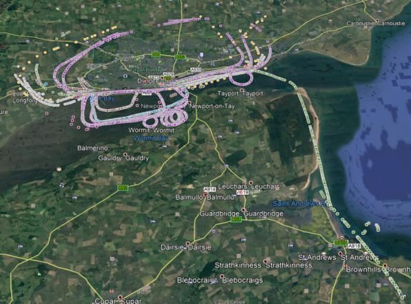
GAINS D3.1 GROUND EQUIPMENT VALIDATION REPORT

Authoring & Approval

Authors of the document
Name/Beneficiary                          Position/Title                                    Date
Dr. Marc Gerlach/FAV                      Work Package Leader 1 WP3                         23/08/2019
Andreas Rossbach/FAV                      Work Package Leader 2 WP3                         16/10/2019

Reviewers internal to the project
Name/Beneficiary                          Position/Title                                    Date
Bob Darby/AOPA                            Work Package Leader WP4                           16/09/2019
Andreia Simoes/HELIOS                     Project Manager                                   25/10/2018
Andy Davis/TRIG                           FS and LS                                         01/11/2019

Approved for submission to the SJU By - Representatives of beneficiaries involved in the project
Name/Beneficiary                          Position/Title                                    Date
Philip Church/HELIOS                      SGA Coordinator                                   29/10/2019
Martin Robinson/AOPA                      FS and LS                                         29/10/2019
Santiago Soley/PILDO                      FS and LS                                         29/10/2019
Marc Gerlach/FAV                          EC                                                29/10/2019
Andy Davis/TRIG                           FS and LS                                         01/11/2019

Rejected By - Representatives of beneficiaries involved in the project
Name/Beneficiary                          Position/Title                                     Date

Document History
Edition          Date                 Status               Author                                      Justification
00.00.00         01/11/2019           Issued               Dr. Marc Gerlach / Andreas Rossbach         Initial issue

Copyright Statement
This document and its content is an internal deliverable of the GAINS project and may not, except with the GAINS consortia
express written permission, be distributed or have its content commercially exploited. This project has received funding
from the SESAR Joint Undertaking under the European Union’s Horizon 2020 research and innovation programme under
grant agreement No 783228. The opinions expressed herein reflect the author’s view only. Under no circumstances shall
the SESAR Joint Undertaking be responsible for any use that may be made of the information contained herein.

                                                                                                                             2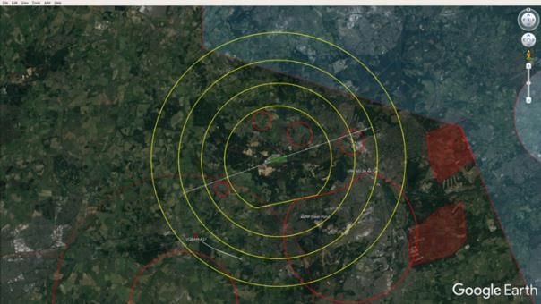
GAINS D3.1 GROUND EQUIPMENT VALIDATION REPORT

GAINS
GENERAL AVIATION IMPROVED NAVIGATION AND SURVEILLANCE

The Ground Equipment Validation Report is part of GAINS, a VLD project that has received funding
from the SESAR Joint Undertaking under the grant agreement No 783228 under European Union’s
Horizon 2020 research and innovation programme. This two-year project initiated in January 2018 is
overseen by a consortium from the general aviation (GA) community: AOPA UK, Pildo Labs, Funke
Avionics and Trig Avionics. Aviation consultancy Helios is the project coordinator.

Abstract
This document summarizes the design and functionality of the GAINS ADS-B ground equipment
provided by f.u.n.k.e. AVIONICS for the project and evaluates its overall performance and suitability
as a supporting tool for the aerodrome staff: Air Traffic Controllers (ATCo), Airfield Flight Information
Service Operators (AFISOs) and Air Ground Communication Operators (AGCS).

For the GAINS demonstrations f.u.n.k.e. AVIONICS investigated suitable options for an air traffic
surveillance display for ground usage, which should meet specific criteria set.

After assessment f.u.n.k.e. AVIONICS decided to use the commercially available RTH80 ADS-B
receiver together with Google Earth Pro as display frontend. A specific interface software enabled
the display of the ADS-B traffic on the map and included various filter settings. Google Earth Pro
provided the required flexibility for map configuration and easy overlay integration.

The ground equipment was installed and used at 8 different airports, and the assessment of its
performance and usability, as recommendations going further, are documented in this document.

                                                                                                            3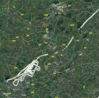
GAINS D3.1 GROUND EQUIPMENT VALIDATION REPORT

Table of Contents
    Abstract ................................................................................................................................... 3
1      Executive summary .................................................................................................... 7
2      Introduction ............................................................................................................... 8
    2.1        Scope ............................................................................................................................ 8
    2.2        Intended readership ...................................................................................................... 8
    2.3        Background ................................................................................................................... 8
    2.4        Structure of the document ............................................................................................. 8
    2.5        List of Acronyms ............................................................................................................ 8
3      Ground ADS-B equipment description ....................................................................... 10
    3.1        General Description ..................................................................................................... 10
    3.2        RTH80 ADS-B Receiver ................................................................................................. 10
    3.3        GP-1090 antenna ......................................................................................................... 11
    3.4        Display Software – Google Earth Pro Viewer................................................................. 11
    3.5        ADS-B Map Software - GAINS.exe ................................................................................ 12
4      Test Sites ................................................................................................................. 15
    4.1        GAINS demonstration locations ................................................................................... 15
5      Reception Quality .................................................................................................... 16
    5.1        Ground Reception Test Brimpton (EGLP) 28-01-2018 .................................................... 16
       5.1.1      Detection range ............................................................................................................................... 16
       5.1.2      Quality of reception ........................................................................................................................ 18
       5.1.3      Reception constraints ..................................................................................................................... 18
    5.2        Fly-In Event Brimpton (EGLP) 09-06-2019 ..................................................................... 18
       5.2.1      Quality of track recording ............................................................................................................... 19
       5.2.2      Quality of reception ........................................................................................................................ 20
       5.2.3      Reception constraints ..................................................................................................................... 20
    5.3        Flight Test Duxford (EGSU) 08-04-2019 ......................................................................... 20
       5.3.1      Ground Equipment Installation ....................................................................................................... 20
       5.3.2      Quality of track recording ............................................................................................................... 21
       5.3.3      Quality of track recording ............................................................................................................... 21
       5.3.4      Evaluation reception quality ........................................................................................................... 22
       5.3.5      Reception constraints ..................................................................................................................... 22
    5.4        Flight Test Sywell (EGBK) 16-04-2019............................................................................ 22
       5.4.1      Ground Equipment Installation ....................................................................................................... 22
       5.4.2      Recorded tracks ............................................................................................................................... 24
       5.4.3      Quality of track recording ............................................................................................................... 25
    5.5        Flight Test Dundee (EGPN) 11-05-2019 ......................................................................... 26
       5.5.1      Ground Equipment Installation ....................................................................................................... 26
       5.5.2      Recorded tracks ............................................................................................................................... 27
       5.5.3      Evaluation reception quality ........................................................................................................... 27
       5.5.4      Reception constraints ..................................................................................................................... 28
    5.6        Flight Test Blackbushe ................................................................................................. 28

                                                                                                                                                                       4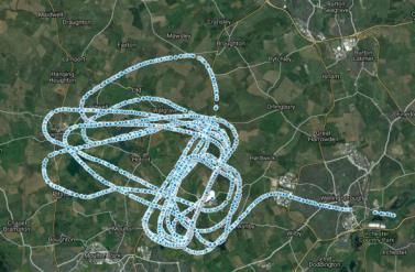
GAINS D3.1 GROUND EQUIPMENT VALIDATION REPORT

       5.6.1      Ground Equipment Installation ....................................................................................................... 28
       5.6.2      Recorded tracks ............................................................................................................................... 29
       5.6.3      Evaluation reception quality ........................................................................................................... 30
       5.6.4      Reception constraints ..................................................................................................................... 30

6      Modifications and Enhancements ............................................................................. 31
7      FISO Comments ........................................................................................................ 32
    7.1        FISO Questionnaire ...................................................................................................... 32
    7.2        FISO / Observer Feedback ............................................................................................ 32
       7.2.1      FISO Feedback Duxford Trials .......................................................................................................... 32
       7.2.2      FISO Feedback Sywell Trials ............................................................................................................ 33
    7.3        Feedback evaluation .................................................................................................... 33
    7.4        Recommendations....................................................................................................... 35
8      Conclusion ............................................................................................................... 36
9      References ............................................................................................................... 37
Appendix A                FISO Questionnaire ................................................................................. 38

List of Tables
Table 1 - List of acronyms ........................................................................................................................ 9
Table 2 - Description of the config file: ................................................................................................. 13
Table 3 – Overview test locations ......................................................................................................... 15
Table 4 – Criteria for reception quality ................................................................................................. 18
Table 5 - Track quality Brimpton ........................................................................................................... 20
Table 6 – Track quality Duxford............................................................................................................. 22
Table 7 – Track quality Sywell ............................................................................................................... 26
Table 8 – Track quality Dundee ............................................................................................................. 27
Table 9 – FISO Feedback 1 ..................................................................................................................... 32
Table 10 – FISO Feedback 2 ................................................................................................................... 33
Table 11 – FISO feedback evaluation .................................................................................................... 34
Table 12 – FISO Questionnaire .............................................................................................................. 39

List of Figures
Figure 1 - RTH80 .................................................................................................................................... 10
Figure 2 - GP-1090 antenna................................................................................................................... 11
Figure 3 – Map Overlays ........................................................................................................................ 11
Figure 4 – Airfield specific overlay (Dundee)......................................................................................... 12

                                                                                                                                                                       5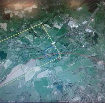
GAINS D3.1 GROUND EQUIPMENT VALIDATION REPORT

Figure 5 – Example of raw data in a log file recorded at Blackbushe ................................................... 13
Figure 6 - Setup of GAINS ADS-B Ground Equipment ........................................................................... 14
Figure 7 – Brimpton Setup..................................................................................................................... 16
Figure 8 – Brimpton flight tracks ........................................................................................................... 17
Figure 9 - Comparison Planesight with 20 Watts and 5 Watts transmit power.................................... 17
Figure 10 - Aircraft tracks at Fly-in Brimpton ........................................................................................ 19
Figure 11 – Track examples with intermittent gaps .............................................................................. 19
Figure 12 – Overlay Duxford.................................................................................................................. 20
Figure 13 – Overview of track records at Duxford ................................................................................ 21
Figure 14 – Installation at Sywell........................................................................................................... 23
Figure 15 – Sywell Overlay .................................................................................................................... 24
Figure 16 - Overview tracks recorded at Sywell .................................................................................... 25
Figure 17 – Dundee Overlay .................................................................................................................. 26
Figure 18 – Installation at Dundee tower.............................................................................................. 26
Figure 19 - Combined track plot Dundee flight tests ............................................................................ 27
Figure 20 – Track record with gaps ....................................................................................................... 28
Figure 21 – Overlay Blackbushe ............................................................................................................ 29
Figure 22 – Overview tracks recorded at Blackbushe ........................................................................... 30

                                                                                                                                                     6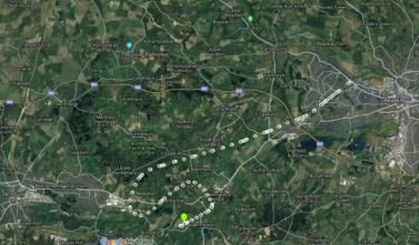
GAINS D3.1 GROUND EQUIPMENT VALIDATION REPORT

1 Executive summary
The objectives of GAINS are to validate, through live flying demonstrations, concepts enabled by
Global Navigation Satellite System (GNSS) and EGNOS. These include a Surveillance Concept
proposing an electronic conspicuity solution and a Navigation Concept proposing instrument flight
procedure elements to meet the needs of GA, including both fixed wing and rotorcraft. GAINS’s
Surveillance and Navigation Demonstrations aim to show the wider aviation community how
improvements being developed by SESAR can be adapted to the respective Concepts enhancing GA
operations without prohibitive cost or certification requirements.

f.u.n.k.e. AVIONICS provided the ADS-B Ground Equipment to be used in the surveillance
demonstrations. This equipment was composed of f.u.n.k.e.’s professional ADS-B receiver RTH80 and
a developed interface software to display the received data on a PC running Google Earth. This
approach provided greater flexibility to adapt various additional features and modifications.

This solution met the project criteria for the air traffic surveillance display for ground usage, namely:

-   The application should run on a tablet PC or laptop computer with an interface to an ADS-B
    receiver with an external 1090 MHz antenna;
-   The application should process all incoming ADS-B signals and should provide a set of filters for
    distance, altitude and type of aircraft;
-   The digital map should be easily adaptable to local airspace structure and airfield data;
-   Zooming and sliding of the map should be possible;
-   The map should include topographic information;
-   The map should allow presentation of data from a data base;
-   Option for additional functionality like conflict detection, analysis of special situations and other
    special functions;
-   The application should have a recording function for the surveillance data and a means to replay
    for later analysis and training purposes.
The ground equipment was installed at eight different locations, using the setup package also
provided by f.u.n.k.e, and was customised according to the specificities of each demonstration
aerodrome.

During demonstrations demo flights were depicted on the display in real time and could be observed
by the aerodrome staff concurrently to their visual airspace observation and radio work. Incoming
ADS-B data were recorded as track records on the computer and were analysed later. About 500
MBytes of demo flights track data were recorded.

The selected ground equipment tested has proved to be simple to setup and reliable in operation
during the trials conducted.

The AFISOs perceived the display itself as very helpful as it improved the situational awareness and
gave them a “feeling of comfort”. Overall, it was well accepted as a means to support the AFISO’s
work.

The main recommendations received asked for a more intuitive configuration and setup and an
extended functionality for later analysis, i.e. a replay function.

                                                                                                            7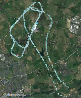
GAINS D3.1 GROUND EQUIPMENT VALIDATION REPORT

2 Introduction
2.1 Scope
This validation report summarizes the design and use of the GAINS ADS-B ground display during the
surveillance demonstrations (WP4), evaluates the received feedback statements and derives
recommendations for ADS-B ground displays.

2.2 Intended readership
The information in this document is intended for those readers who require a more detailed view of
the GAINS surveillance demonstrations, and about the use of ADS-B ground displays.

2.3 Background
Most ADS-B ground display applications are not developed for specific airfields and hence do not
represent the relevant airspace structure and special situations around individual airfields. They also
do not process locally received ADS-B In data but use special internet formats and data from
unknown sources and quality.

In GAINS project an application was requested that depicts surveillance data on a digital computer
map. The application should show ADS-B/surveillance data transmitted by air traffic around an
airfield to verify if ADS-B data can improve flight safety at uncontrolled aerodromes with different
kinds of traffic.

The application should be used during a set of flight tests to support airfield/aerodrome flight
information officers (AFISO) or similar personnel issuing flight information to approaching aircraft, to
aircraft in the traffic pattern or any air traffic near the airfield. The intention was to see how ADS-B
equipped aircraft can enhance traffic safety on airfields which do not have radar or other means for
visualization of the actual traffic.

2.4 Structure of the document
The first part describes Ground ADS-B equipment and its components (§3).

The second part analyses the reception quality at the different test locations (§4 and §5).

The third part lists the modifications and enhancements implemented during the GAINS project (§6)

The fourth part summarizes and evaluates the received feedback (§7)

The fifth part includes the summary and the recommendations (§8)

2.5 List of Acronyms
Acronym                   Definition

AFISO                     Airfield Flight Information Service Operator

                                                                                                           8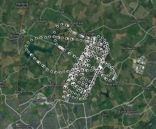
GAINS D3.1 GROUND EQUIPMENT VALIDATION REPORT

Acronym                  Definition

AGCS                     Air Ground Communication Service
AGL                      Above Ground Level
ALARP                    As Low As Reasonably Practical
ANSP                     Air Navigation Service Provider
ATC(o)                   Air Traffic Control
ATS                      Air Traffic Service(s)
CAIT                     Controlled Airspace Infringement Tool (NATS)
CAS                      Controlled Air Space
CDTI                     Cockpit Display of Traffic Information
EC                       Electronic Conspicuity
FASVIG                   Future Airspace VFR Implementation Group
FAV                      f.u.n.k.e. Avionics – GAINS partner organisation
FISO                     Flight Information Service Officer
FLARM                    Flight Alarm (Proprietary ADS-B system developed originally for use in
                         gliders)
GA                       General Aviation
GAINS                    General Aviation Improved Navigations and Surveillance
MAC                      Mid Air Collision
NATS                     National Air Traffic Services (UK ANSP)
NOTAM                    Notice to Airmen
PAW                      Pilot Aware (Proprietary ADS-B system)
PPR                      Prior Permission Required (aerodrome usage constraint)
RTH80                    FAV Ground Surveillance Equipment (See Appendix B)
TOI                      Temporary Operating Instruction
UTP                      Unit Training Plan
                                       Table 1 - List of acronyms

                                                                                                  9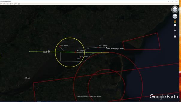
GAINS D3.1 GROUND EQUIPMENT VALIDATION REPORT

3 Ground ADS-B equipment description
3.1 General Description
The GAINS Ground ADS-B Equipment was developed around the RTH80 ADS-B receiver with the goal
to have a very flexible and easy to configure traffic display for small airfields and aerodromes. The
local installation of the reception system ensures the direct, immediate and reliable reception of all
ADS-B emissions from the aircraft in the vicinity of an airfield.

The ADS-B reception part consists of the RTH80 receiver, the cable set and an easy-to-mount outdoor
antenna. The display part requires a notebook or PC and a router.

The complete ADS-B Ground Equipment hardware consists of following components:
    •   1 x RTH80, Traffic Receiver, SN Sample No. 81
    •   1 x KSRTH80, Connection Cable serial for RTH80
    •   1 x Power Supply "Voltcraft" for RTH80
    •   1 x Antenna WiMo GP-1090 for the RTH80
    •   1 x Mounting Set for WiMo GP-1090
    •   1 x Antenna Cable N-SMA, 10m
    •   1 x Adapter SMA/BNC
    •   1 x Notebook ASUS F540UA-DM304T, SN J1N0GR03T737032
    •   1 x LAN/USB-Adapter Anker SN 22UNAGV7
    •   1 x Power Supply "ASUS" for Notebook ASUS
    •   1 x DLink WLAN-Router DIR-300, SN P1NJ195003816
    •   1 x Power Supply for DLink LF5R02091603336

The ADS-B Ground Equipment software consists of the Google Earth Pro Viewer and the GAINS
interface software “ADSB-Map”.

3.2 RTH80 ADS-B Receiver
The RTH80 detects and decodes incoming ADS-B data on the 1090MHz radar response frequency and
forwards this to a PC for being displayed traffic targets on a digital map.

The following Mode-S message types are processed by the
RTH80:
•       Mode-S Replies (short and long)
•       Mode-S Acquisition Squitter
•       Mode-S Extended Squitter

Mode-A and C messages are ignored and are not processed by
the RTH80.

The receiver sensitivity (Minimum Trigger Level – MTL) is better
than -76 dBm. If a valid preamble is detected, the decoding of               Figure 1 - RTH80
subsequent pulses (which contains the message information)

                                                                                                         10
GAINS D3.1 GROUND EQUIPMENT VALIDATION REPORT
starts. Message length (56 or 112 bit) is determined by decoding first 5 bits (containing the DF
number). The decoded message can be sent out via an RS232 port, a USB port or a fast Ethernet
Interface (TCP/UDP) for further processing on another device (e.g. for traffic depiction).
In the GAINS project, the RTH80 receiver was connected to a PC via the Ethernet interface, directly
without a network.
3.3 GP-1090 antenna
The GP-1090 antenna is a narrow band antenna, designed for secondary radar (IFF) from 1070 to
1110 MHz. Due to the omnidirectional characteristic and the medium gain the reception is good in
any direction, also upwards.
Technical Data of the GP-1090 antenna
• Gain: 5 dB ±0.5dB
• Length: ca. 53cm incl. mast clamp
• Weight: ca. 700g
• For mast diameter from 30 to 50mm
• Connector: N female Figure 2 - GP-1090 antenna
3.4 Display Software – Google Earth Pro Viewer
Several options were examined to find a suitable digital map (e.g. Open Street Map, Google Maps,
SIMPLYMAPS, Google Earth, …). The map should be freely available and offer easy configuration and
overlay options. It was decided to use Google Earth, as is free access and allows you to incorporate
aviation specific information into the map display such as approach charts, preferred approach
routes, reporting points, noise-sensitive areas, obstacles and much more. This information is stored
in separate kml / kmz files (kml = keyhole markup language, kmz = kml zipped). Furthermore, there
are numerous aviation specific kml / kmz files available for Google Earth, such as airspace data for
Germany, UK and most other European Countries.
Database for UK Airspace Overlay Approach Chart EDNY
Figure 3 – Map Overlays
11GAINS D3.1 GROUND EQUIPMENT VALIDATION REPORT
Comment: Note that the 3D depiction of airspace data was not found useful, because as the
centre of the display is moved, the apparent position of the airspace boundaries changes.
Therefore, the airspace boundaries need to be “clamped to ground” and only those that are in
the neighbourhood of the aerodrome and up to about 4000ft above aerodrome level are useful
for the display. Google Earth allows flexible selection and deselection of items for display.
3.5 ADS-B Map Software - GAINS.exe
Google Earth provides the possibility to import data and to display these on the map view. For the
GAINS trials, f.u.n.k.e. AVIONICS programmed the interface software “ADSB-Map” which receives the
decoded messages from the RTH80, and processes and forwards them to the Google Earth viewer.
The forwarded data comprise all current received positions of aircraft at an update rate of up to one
second (3 seconds default), supplemented by the height, the call sign and a history track. The map
display itself can still be scaled, rotated and different viewing angles selected.
Figure 4 – Airfield specific overlay (Dundee)
The interface software “ADSB-Map” offers a number of helpful settings, such as different filter values
to exclude non-relevant traffic and the length and colour of the track history and other items. These
settings are stored in the ADSB-Map configuration file „Gains.config“. The configuration file can be
edited with any editor, e.g. word pad. Changes are applied by relaunching the Gains.exe programme.
[GENERAL] Reference Position (your own position) to determine the distance to the
REFPOS_LAT=48.400133 aircraft received from the RTH80
REFPOS_LON=9.980466
REFPOS_ALT=480
LOGGER=1 ➔ log files will be created to store incoming target data. Each file logs the
data of one hour and automatically creates a new file thereafter. The file
12GAINS D3.1 GROUND EQUIPMENT VALIDATION REPORT
name contains date and time to distinguish the different logs from one
another.
[INPUT] determines the how data are fed from the RTH80
COM=0 ➔ Number of serial port, only when COMTYPE=”COM”
COMTYPE=udp ➔ here „udp“, „tcp“ and „com“ can be set
(under Linux also „ttyS“ resp. „ttyUSB), udp is default.
IP=192.255.255.255 ➔ IP-address of RTH80 at COMTYPE=”tcp”
for COMTYPE=”udp” the broadcast address is sufficient
PORT=16001 ➔ TCP resp. UDP port for reception
[GOOGLE]
SYMBOL=0 ➔ 0 = Dot Symbol, 1 = Aircraft Symbol with direction information
CLAMP2GROUND=1 ➔ 1 = distance between ground and aircraft is NOT shown
TREND_ALT=0 ➔ 0 = no altitude trend (+/-) is given
TREND_AC=0 ➔ 0 (just for future use)
USE=1 ➔ 1 = generation of data for Google Earth
HEIGHT_FILTER_MAX=27000 ➔ only aircraft below this altitude are shown (altitude in feet)
HEIGHT_FILTER_MIN=0 ➔ only aircraft above this altitude are shown (altitude in feet)GAINS D3.1 GROUND EQUIPMENT VALIDATION REPORT
The ADS-B Ground equipment was delivered with a setup instruction for Google Earth and a guidance
how to change settings and how to include existing charts and to draw own overlays.
Figure 6 - Setup of GAINS ADS-B Ground Equipment
14GAINS D3.1 GROUND EQUIPMENT VALIDATION REPORT
4 Test Sites
4.1 GAINS demonstration locations
Formal demonstration flights took place at six locations: Stapleford, Brimpton, Duxford, Sywell,
Dundee and Blackbushe. There was a problem with the ground reception settings at Stapleford, so
no transmissions were recorded during this test campaign. At the other locations the ADS-B ground
equipment worked as intended and test data is available.
During the course of the GAINS project, the ground surveillance equipment was set up at several
other locations, for various purposes as described in GAINS deliverable D4.4 “Aerodrome Operations
Demonstration Report”, and recordings were made of the ADS-B data received. The following table
gives an overview of the test locations.
Aerodrome Date of tests Purpose No. of a/c track records
Duxford - EGSU 08. April 2019 formal demonstration 6 a/c – 6 records
Sywell - EGBK 16. April 2019 formal demonstration 8 a/c – 8 records
Dundee - EGPN 11. May 2019 formal demonstration 9 a/c – 8 records
Blackbushe - EGLK 16. August 2019 formal demonstration 5 a/c - 5 records
Brimpton - EGLP 28. January 2019 ground reception tests 1 a/c - 4 records
Brimpton - EGLP 09. June 2019 fly-in event 6 a/c – 6 records
initial eye tracking
Lee-on-Solent - EGHF 30. March 2019 no track evaluation
equipment test
Barton - EGCB 25. May 2019 equipment set up no track records
Wycombe - EGTB 13.-15. June 2019 AeroExpo 10 a/c – 10 records
Table 3 – Overview test locations
15GAINS D3.1 GROUND EQUIPMENT VALIDATION REPORT
5 Reception Quality
5.1 Ground Reception Test Brimpton (EGLP) 28-01-2018
The first test with GAINS ADS-B surveillance was conducted at Brimpton airfield. A very simplified
overlay was created for that airfield.
The installation location for the ADS-B reception antenna was very good
with no major shadowing. 4 flights have been made with aircraft GOBJT, two
test flights with a Planesight unit on-board and two with different SkyEcho
devices.
All flights were also observed with the online flight tracker “flightradar24”.
Brimpton antenna installation Screen Photograph GAINS display Brimpton
Figure 7 – Brimpton Setup
5.1.1 Detection range
The PlaneSight unit was flown in both available variants: one with 5 Watts and the other with 20
Watts transmission power. The reception of both units can be described as very good up to a
distance of approximately 10 kilometres. The 20 Watts version shows good quality up to a distance of
20 km.
The picture below shows the four devices (PS 5W blue, PS20W red, SkyE1 green, SkyE2 yellow) as
position plots on Google Earth. Interferences can be observed when the aircraft is flying directly
towards the RTH80 Antenna. This may be caused by the engine or the pilot which may disturb the
transmission in flight direction.
16GAINS D3.1 GROUND EQUIPMENT VALIDATION REPORT
At this test the 5 Watt transmission power of the Planesight unit seems to be the lower limit for a
reliable reception up to 10 kilometres. The SkyEcho devices degrade at greater distances.
Figure 8 – Brimpton flight tracks
Figure 9 - Comparison Planesight with 20 Watts and 5 Watts transmit power
17GAINS D3.1 GROUND EQUIPMENT VALIDATION REPORT
5.1.2 Quality of reception
The track recordings of all devices are continuous. Observed gaps are either caused by low
transmission power (Planesight 5 Watts variant) or by absorbance caused by the engine or pilots. The
reception quality of the ADS-B ground equipment during this test is fully sufficient for such
aerodromes.
Note: Quality of reception was rated from 1 = poor quality to 10 = excellent quality according
to following criteria:
Rating Quality Criteria
continuous track with sporadic gaps only, no position jumps and other
9-10 excellent
discrepancies
7-8 very good mostly continuous track with some minor gaps only and insignificant jumps
longer gaps and greater jumps in position record, but track continuity still
5-6 good
identifiable
gaps over a longer period, greater jumps or obvious wrong position records, but
3-4 sufficient
track can still be identified
1-2 poor only sporadic position records, track can hardly be identified.
Table 4 – Criteria for reception quality
Note: all aircraft IDs are anonymized
5.1.3 Reception constraints
No reception constraints were observed.
5.2 Fly-In Event Brimpton (EGLP) 09-06-2019
During the fly-in event at Brimpton the ADS-B transmission of six aircraft were recorded. Four
records show the track of their approach and landing.
18GAINS D3.1 GROUND EQUIPMENT VALIDATION REPORT
Figure 10 - Aircraft tracks at Fly-in Brimpton
5.2.1 Quality of track recording
The track records of 4 aircraft (GLPAA, GLPBB, GBKAA, GLPCC) are continuous without major gaps.
The track of GLPDD and GLPEE show few, but periodic intermittent gaps. The reason for this is
unknown.
Track GLPDD Track GLPEE
Figure 11 – Track examples with intermittent gaps
19GAINS D3.1 GROUND EQUIPMENT VALIDATION REPORT
The table below is an overview on the quality of the track records and thus on the reception quality.
Aircraft Distance Quality: 1-poor / 10 Excellent
GLPDD 7.5km 7 ( intermittent, gaps)
GLPAA 8.7km 9
GLPBB 24km 8 (some gaps)
GBKAA 15.4km 9 (some gaps > 15km)
GLPCC 21km 9 (some gaps > 15km)
GLPEE 14km 7 (periodic gaps)
Table 5 - Track quality Brimpton
5.2.2 Quality of reception
All aircraft were reliably detected. The reception quality of the ADS-B ground surveillance equipment
was continuously good.
5.2.3 Reception constraints
No reception constraints were observed.
5.3 Flight Test Duxford (EGSU) 08-04-2019
5.3.1 Ground Equipment Installation
For the Duxford flight tests an overlay was created. No problems concerning setup and configuration
of the ground equipment were reported.
Duxford overlay Screen Photograph GAINS display Duxford
Figure 12 – Overlay Duxford
20GAINS D3.1 GROUND EQUIPMENT VALIDATION REPORT
5.3.2 Quality of track recording
The ADS-B transmissions of 6 aircraft were extracted and analysed from the track log recorded by the
GAINS ADS-B ground surveillance equipment.
Track GSUAA Track GSUEE
Track GSUBB Track GSUFF
Track GSUDD Track GSUCC
Figure 13 – Overview of track records at Duxford
5.3.3 Quality of track recording
Aircraft Equipment Distance Quality: 1-poor / 10 Excellent
Mode S ES transponder (SIL=0)
GSUAA ca. 16km 10
Pilot Aware
GSUBB PS20 ca. 10km 7 (some dropouts)
21GAINS D3.1 GROUND EQUIPMENT VALIDATION REPORT GSUCC GTX345
GAINS D3.1 GROUND EQUIPMENT VALIDATION REPORT

                                   Figure 14 – Installation at Sywell

There were some positive comments about the ADS-B display for Sywell. The grey-out overlay was
set to colour black with low transparency, obscuring the satellite background map, so that it was
almost like a radar display. The FISO preferred this and the chosen the level of detail shown.

The details shown were:
    • the ATZ;
    • runway extended centrelines with mile markers;
    • noise sensitive areas (red circles);
    • helicopter reporting points (blue triangles).

                                                                                                    23
GAINS D3.1 GROUND EQUIPMENT VALIDATION REPORT
Figure 15 – Sywell Overlay
5.4.2 Recorded tracks
The tracks of eight aircraft were extracted from the RTH80 track log file:
Track GBKFF Track GBKGG
Track GSUAA Track GBKCC
24GAINS D3.1 GROUND EQUIPMENT VALIDATION REPORT
Track GBKBB Track GBKEE
Track GBKAA Track GBKDD
Figure 16 - Overview tracks recorded at Sywell
5.4.3 Quality of track recording
Track Quality
AIRCRAFT ADS-B-IN ADS-B-OUT
1-poor / 10 Excellent
GSUAA PIPER PA-
PAW +tablet Mode S ES 9
28R-180
GBKCC Cessna 182P PlaneSight PlaneSight 8
25GAINS D3.1 GROUND EQUIPMENT VALIDATION REPORT
GBKFF PA‐28R‐200‐ Garmin GTX330 ES
PAW Rosetta+tablet 10
2 transponder
GBKBB SKYRANGER PAW+SkyDemon PlaneSight 8
GBKEE Groppo Trail PlaneSight PlaneSight 9
GBKAA SKYRANGER
PAW + Sky Demon Trig TT21+GPS ADS-B out 10
NYNJA 912S(1)
GBKGG PIPER PA-31
TAS Garmin GTX 330 ES 9
NAVAJO
GBKDD Sky Ranger Pilot Aware + tablet Trig TY91 with ADSB 9
Table 7 – Track quality Sywell
5.5 Flight Test Dundee (EGPN) 11-05-2019
5.5.1 Ground Equipment Installation
Overlay Dundee Overlay Dundee with activated backplane
Figure 17 – Dundee Overlay
Dundee Tower Dundee antenna installation
Figure 18 – Installation at Dundee tower
26GAINS D3.1 GROUND EQUIPMENT VALIDATION REPORT
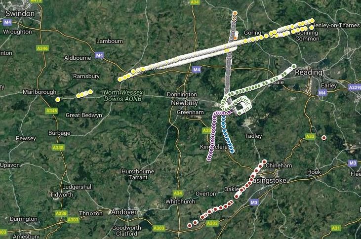
5.5.2 Recorded tracks
Figure 19 - Combined track plot Dundee flight tests
Aircraft Equipment Distance /Alt Quality: 1-poor / 10 Excellent
GPNBB Trig 6.4nm/1432ft 9
GPNGG GTX328 6.0nm/1058ft 9
GPNHH PS20W ca. 6.5nm 8
GPNEE SkyEcho 3.7nm/957ft 9
GPNDD SkyEcho 3.4nm/1357ft 7 (interruptions)
GPNCC SkyEcho + Skydemon 3.6nm/684ft 3 (spurious)
GPNAA TT21 7.1nm/1810 8
Table 8 – Track quality Dundee
5.5.3 Evaluation reception quality
The overall reception quality of the ADS-B ground equipment was good, but there were more gaps in
the track, when a/c flew north of Dundee.
The ADS-B transmission of GPPLG showed jumps in the a/c position.
27GAINS D3.1 GROUND EQUIPMENT VALIDATION REPORT
Figure 20 – Track record with gaps
The problem is most probably related to the airborne equipment and cannot be associated with the
ground-based ADS-B reception part.
5.5.4 Reception constraints
The extracted tracks show a significant worse track quality to the north. This quality reduction results
from the topographic situation north of Dundee airport where the ground steeply rises and disturbs
the reception. In contrast, the reception quality to the south over plain water was much better.
Aircraft GBNON equipped with a Planesight unit with 20 Watts Tx out was well received beyond 20
nm.
5.6 Flight Test Blackbushe
5.6.1 Ground Equipment Installation
A customized overlay for the Bluckbushe airport (EGLK) was implemented for the flight tests.
28GAINS D3.1 GROUND EQUIPMENT VALIDATION REPORT
Figure 21 – Overlay Blackbushe
5.6.2 Recorded tracks
Air traffic around Blackbushe airport was recorded for approximately 3.5 hours, from 07:43 GMT to
11:20 GMT. The tracks of five aircraft were extracted and plotted.
Track GLKAA Track GLKDD
29GAINS D3.1 GROUND EQUIPMENT VALIDATION REPORT
Track GLKEE Track GLKCC
Track GLKBB
Figure 22 – Overview tracks recorded at Blackbushe
5.6.3 Evaluation reception quality
All aircraft flew in the traffic circuit and locally around the airfield. GLKAA, GLKDD, GLKEE showed
good air-air and good air-ground reception. GLKCC did not re-enable the PlaneSight transmission
after power down, so that, although he had good sight of the other a/c, this aircraft was invisible to
all others. GLKBB had equipment problems but showed up briefly.
Aircraft Equipment Distance Track Quality: 1-poor / 10-excellent
GLKAA Transponder TT31 / ext. antenna 3,1nm 9
GLKDD SkyEcho1 5,3nm 8
GLKEE SkyEcho2 3,7nm 9
GLKBB Garmin GTX345 9,7nm 4
GLKCC PlaneSight -- n/a
Table 9 – Track quality Blackbushe
5.6.4 Reception constraints
No constraints.
30GAINS D3.1 GROUND EQUIPMENT VALIDATION REPORT
6 Modifications and Enhancements
During the GAINS project the functionality of the GAINS Ground ADS-B equipment was continuously
amended and modified according to the feedback received.
The following points have been added / modified:
During equipment testing some customisation were made on request, such as:
• Altitude label is in one line next to the aircraft name;
• Altitude format changed to FL;
• Two additional aircraft symbols were introduced: a red dot for aircraft with valid data and a black
dot for aircraft with obsolete data;
• Total number of possible active aircrafts increased, bug removed when deleting / adding aircraft
in the active aircraft array;
• Inclusion of log file generation;
• Log switch in the configuration file and creation of a new log file after 1 hour of recording
• GAINS.exe output changed to one line per aircraft;
• Output of basic parameters of the config-file at start of program for verification;
• Function added: “clamp to ground selectable” in order to get rid of the altitude line;
• Function added: “aircraft symbol or dot selectable”;
• Output of “altitude trend selectable”;
• Output of aircraft label changed: first position altitude, second position call sign;
• Console program delivered to add time stamps to the log file (addTimeStamp.exe);
• Selection of different colours of history track adjustable in the configuration file;
• Continuous update of set-up instructions (latest version 1.4).
Some other improvements are foreseen in the future, such as:
• Simple replay function;
• Extraction and replay of selected tracks;
• Plot of tracks for inclusion in documents;
• Squawk indication;
• Further functions for recorded flight analysis.
31GAINS D3.1 GROUND EQUIPMENT VALIDATION REPORT
7 FISO Comments
7.1 FISO Questionnaire
A set of questions were submitted to the FISOs after the flight trials in form of a questionnaire.
(see Appendix A - FISO Questionnaire), the results are provided in the following sections.
7.2 FISO / Observer Feedback
There was no FISO feedback from all flight test events. The most comprehensive feedback was
received from the AFISOs at Duxford.
7.2.1 FISO Feedback Duxford Trials
The FISOS from Duxford filled in the feedback form
Feedback on questions 1 – 11:
No. Role Q1 Q2 Q3 Q4 Q5 Q6 Q7 Q8 Q9 Q10 Q11
N/A yes
(not yet (not all
1 observer N/A N/A N/A 10 yes 0 no 10 8
advised a/c
by CAA) visible)
2 observer N/A 0 N/A 10 yes 10 no 10 3 10 no
3 FISO - - - 10 yes 7 no 10 10 8 -
FISO &
4 10 0 N/A 10 yes 4 no 8 4 8 yes
Observer
Ø 10 5,25 9,5 4,25 8,5
Table 9 – FISO Feedback 1
Feedback on questions 12 and 13:
No. Role Q12: Any recommendations for the ground display? Q13: Any recommendations for EC devices?
- adjustable orientation instead of North-Up
1 observer - larger data blocks
- shorter trails -
- height filter (> 5000 ft)
- topographic display confusing
32GAINS D3.1 GROUND EQUIPMENT VALIDATION REPORT
No. Role Q12: Any recommendations for the ground display? Q13: Any recommendations for EC devices?
- several occasions when display helped, e.g.
reports crosswind (downwind?) when
actually base
2 observer - adjustable orientation instead of Noth-Up - A/C on wide circuit may not have field in
- height filter (gnd a/c) sight
- topographic display confusing - when introduced, FISO will need to ensure
that they do not use display as primary
source, i.e. must use as primary/display as
secondary.
- as FISO operating did not have access to display
information passed by others who had access to
display
3 FISO - information passed was very useful to my situational -
awareness of where A/C were. Especially as A/C was
not visible in the circuit.
- a better traffic information source.
- display orientated S/North instead of North/South to
FISO & reflect aspect when looking out of window.
4
Observer - altitude when on ground was 325 ft, should be QFE or
126/125 QNH A/C to display when on ground
Table 10 – FISO Feedback 2
A further feedback was given one day after the flight trial by email. At least two FISOs found the
display background too cluttered. Instead of Google Earth, Google Maps should be used as it is less
cluttered and could provide more accurate position information to the emergency services, if
necessary.
7.2.2 FISO Feedback Sywell Trials
One of the Sywell FISOs commented that the track display label would be better if it was “callsign /
altitude” rather than “altitude / callsign”. The requested change was implemented before the next
flight tests at Dundee airport started.
7.3 Feedback evaluation
The table below gives an overall feedback on the GAINS ADS-B ground surveillance system:
Q Function Rating
1 Equipment installation easy
Overlay customisation and overlay modification was
carried out by GAINS in advance of the formal
demos, but in consultation with the aerodrome
2 Overlay customisation staff, so that the demo could concentrate on the
display as it might be used operationally. It took a
couple of hours each time to build the fairly simple
overlay data used for each aerodrome in the demos.
3 Overlay modification see above
33GAINS D3.1 GROUND EQUIPMENT VALIDATION REPORT
4 Improvement of situational awareness very much (max points)
5 Used to spot traffic yes (all users)
6 Frequency of usage medium
7 Distraction to look outside No
8 Display gives “comfortable feeling” yes (9,5 of 10)
9 Decisions based on display information medium (4,25 of 10)
10 Update rate and precision very good (8,5/10)
11 Perceived problems not all a/c visible
12 Recommendations ground display see below
shall not be used as primary device
13 Recommendations EC devices
see validation report Airborne Equipment
Table 11 – FISO feedback evaluation
The most important point in the feedback on the ground display is the statement, that not all aircraft
were visible on the display all the time. Such failure can be attributed essentially to following
reasons:
1. The airborne ADS-B equipment did not transmit the position. This may be caused by either a
faulty device or by wrong operation, e.g. not activated transmission.
2. Unfavourable ADS-B antenna position: the transmission is either shielded by the motor block
or the pilot or by the a/c especially during turns with high bank angles.
3. Unfavourable ground antenna location: shielding by buildings, trees or topographic
conditions.
4. Defect of the ADS-B Receiver or software bug in the interface software
As only singular aircraft were not displayed a fault of the ADS-B ground display is unlikely. However,
the category of ADS-B display is designed as a supplemental means and is not intended to substitute
an official ATC radar.
A further significant point of criticism is about the map display background. The normal Google Earth
map was found to be too cluttering and distracting from the air traffic situation. This problem could
be solved by inserting a black background plane obscuring the background map depiction.
Unfortunately, this also hides all the topologic information of the background which may be useful in
some situations. Google Earth, however, allows to adjust the opacity of various objects between 0%
and 100%. This feature was added to the black plane object so that now the AFISO can decide how
much of the background information should still be visible according to his personal preferences
while at the same time this is minimizing the effect of overloading the map display with disturbing
information.
Most of the other critical remarks were due to the fact that there was no time to give the AFISOs an
adequate introduction about the settings and adjustment features of the GAINS Ground ADS-B
display, especially at the first test campaigns when those points were not yet known. Especially, the
34GAINS D3.1 GROUND EQUIPMENT VALIDATION REPORT
numerous many settings and configuration options of Google Earth were unknown to the users.
However, almost all problems could be solved by applying the existing functions for:
• adjustment of map orientation;
• suppression of map background;
• setting the lower and upper height filters;
• adjustment of the length of track history;
The only point left is the request for a larger data block. This point is copied and will be implemented
in the ADS-B map software at a later stage.
7.4 Recommendations
Despite nearly all required functions were implemented in the GAINS ground equipment, its
existence and adjustment were not obvious to the user. Therefore, it is recommended to include a
dedicated menu, where map customisation and filter settings can be directly entered, controlled and
changed.
The data block for an aircraft should be larger and offer customisation. The configuration of the data
block should also be possible via a separate menu.
A replay function could not be included during the GAINS demonstration project but is clearly a
useful feature. The replay function should read a recorded log file and feed the data back into the
interface software for displaying it on Google Earth as if that data came from the router.
Selection of time period and dedicated playback of selected aircraft would offer enhanced analysis
possibilities.
35GAINS D3.1 GROUND EQUIPMENT VALIDATION REPORT
8 Conclusion
There were some minor problems during the initial setup of the GAINS ADS-B ground equipment
which could be solved rather quickly. From the second formal demonstration at Duxford, the ADS-B
display worked satisfactorily and showed the surrounding traffic reliably. The recording function
produced track log files, which were used for post flight analysis.
The setup was not complicated and the system was very reliable during all flight tests of the GAINS
project. With Google Earth as display frontend it was quite easy to integrate specific background
overlays for each test site.
The display itself was perceived by the AFISOS as very helpful, which definitely improves the
situational awareness.
The recommendations from the GAINS project will be picked by f.u.n.k.e. AVIONICS to develop this
software further. The software will be offered as a complement to the RTH80 ADS-B receiver.
36GAINS D3.1 GROUND EQUIPMENT VALIDATION REPORT
9 References
Reference Documents
[1] Manual for ADS-B Ground Surveillance Display
“Setup Google Earth as GAINS Surveillance System” V1.4, issued 26-02-2019
[2] Manual Operation and Installation of RTH80 ADS-B / Mode-S Receiver
Document No. 03.234.010.71e, Rev. 1.01, issued 16-02-2017.
37GAINS D3.1 GROUND EQUIPMENT VALIDATION REPORT
Appendix A FISO Questionnaire
1. Was the installation / placement of the ground equipment easy or difficult?
difficult 1 2 3 4 5 6 7 8 9 10 easy
2. Did you customize the local overlays delivered with the GAINS equipment to your local
aerodrome?
no of
overlays
0 1 2 3 4 5 6 7 8 9 10 added or
modified
3. If yes, was it difficult to modify the given overlays (add, change the items)?
difficult 1 2 3 4 5 6 7 8 9 10 easy
4. Do you have the impression that your situational awareness is improved by the GAINS traffic
display?
not at all 1 2 3 4 5 6 7 8 9 10 very much
5. Did you use the traffic display to spot nearby aircraft?
yes no please tick box
6. Did you once or more look at the traffic display to better understand the traffic situation in the
traffic pattern or around the aerodrome (to check what was going on)? (per day)
more than
0 1 2 3 4 5 6 7 8 9 10
10 a day
7. Does the equipment make you look less out the window?
yes no please tick box
8. Did you feel more comfortable when receiving permanent position information of the aircrafts
in your vicinity?
not very
1 2 3 4 5 6 7 8 9 10
relevant supportive
38GAINS D3.1 GROUND EQUIPMENT VALIDATION REPORT
9. Did you make any traffic hints or traffic advices based on the traffic display? (per day)
more than
0 1 2 3 4 5 6 7 8 9 10
10 a day
10. Do you think that update rate and data precision is good enough to assess the traffic situation?
not at all 1 2 3 4 5 6 7 8 9 10 perfect
11. Did you notice any major problems with the data depiction on the traffic display?
yes no please tick box
if yes, please describe
kind of problem
12. Do you have any function or any other recommendation in mind that could improve the Gains
Ground Equipment?
Comments:
13. Other comments on any of the EC devices and recommendations for further.
Comments:
Table 12 – FISO Questionnaire
39GAINS D3.1 GROUND EQUIPMENT VALIDATION REPORT
40You can also read