INTERTENANCY APARTMENTS SYSTEMS - KOROK
←
→
Page content transcription
If your browser does not render page correctly, please read the page content below

KOROK®

INTERTENANCY
APARTMENTS
SYSTEMS

CBI 5171
FEBRUARY 2021   KOROK
KOROK®

INTERTENANCY
APARTMENTS
SYSTEMS

SECURE, QUIET,                                                QUIET
                                                              KOROK® panels offer superior mass over traditional
FLEXIBLE.                                                     timber and plasterboard or equivalent systems resulting
                                                              in enhanced sound attenuation, particularly in the more
Multi-unit construction projects, such as apartments, call
                                                              invasive lower frequencies. This means that residents are
for well-tested technology that’s simple to install. KOROK®
                                                              comfortable in their own space without the intrusion of
Intertenancy wall offers the benefits of proven fire and
                                                              noise from other dwellings.
acoustic performance, and the security of a solid wall
design.
                                                              FLEXIBLE
SECURE                                                        Because KOROK® panels provide all the fire protection you
                                                              need, you can run electrical and plumbing services on the
KOROK® panels consist of a steel shell filled with aerated
                                                              inter-tenancy wall, without the need for special penetration
concrete. Having a solid wall provides peace of mind
                                                              seals around each pipe or light switch. This allows you
to occupants’ in the knowledge that they are physically
                                                              the flexibility of placing a TV and kitchen where you
separated from neighbouring dwellings.
                                                              want, and the ability to hang fixtures on the wall without
                                                              compromising the fire and acoustic resistance of the Inter-
                                                              tenancy wall.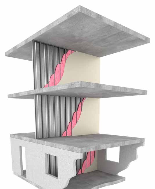
Due to its unique composition, KOROK® provides
 This manual has been developed using
                                                        exceptional fire resistance over a long period of
 recognised Australian and New Zealand
                                                        time.
 Standards together with sound engineering
 principles substantiated through BRANZ.                However, to achieve the stated fire resistance
                                                        ratings, it is critically important to adhere strictly
 This manual in no way supersedes the
                                                        to the design, installation and construction
 requirements of any Statutory Authority or New
                                                        details otherwise the fire resistance rating may be
 Zealand Building Code but is rather a guide
                                                        degraded.
 to the performance of KOROK® under certain
 loading conditions.                                    KOROK® panels have been tested and appraised by
                                                        the Building Research Association of New Zealand
 The manual provides builders, engineers,
                                                        (BRANZ). In some cases, a fire resistance rating
 designers and architects with a user-friendly
                                                        has been based on an appraisal from the same
 format for installing and designing KOROK® for
                                                        organisation.
 non-load bearing applications.
                                                        Where specific acoustic control performance is
 In brief, KOROK® has:
                                                        required, KOROK® can provide a number of proven,
 • Fire rated systems ranging from 30 minutes to 240    acoustic-rated wall systems, or can assist in
   minutes.                                             developing a fully customised solution.
 • Acoustic systems ranging from STC 36 to STC 76.

 • Panel dimensions of 250mm wide, in lengths up to
   9.3 metres.

 • Panels that weigh (nominally) 10.2kg per lineal
   metre.

 • Panels available in galvanised or colour steel.

 Typical Applications are:
 • Dividing and boundary walls for sheds, factories
   and warehouses.

 • Cinema walls.

 • Intertenancy walls for apartments, terraced
   housing, hotels and retirement complexes.

 • Lift shaft and duct walls.

 • Acoustic barriers.

              Appraisal No.1059 [2019]                                Appraisal No.559 [2020]

KOROK® INTERTENANCY APARTMENTS SYSTEMS www.korok.com 0800 773 777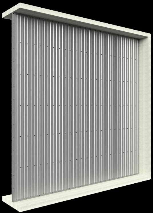
CONTENTS
INTRODUCTION                                                                                                     1      TABLE 3 - KOROK® FASTENERS SPACINGS                                                                         25
Acoustic performance..............................................................................1
Fire performance.........................................................................................1              PANEL PROPERTIES                                                                                            26
100% reusable, minimum waste.........................................................1
                                                                                                                        KOROK® panels.........................................................................................26
Use only the Current Specification....................................................2
                                                                                                                        Loading combinations...........................................................................26
Beware of Substitutions...........................................................................2
                                                                                                                        General design notes.............................................................................26
Purpose.............................................................................................................2
                                                                                                                        References...................................................................................................26
Scope of Use.................................................................................................2
                                                                                                                        Manufacturers documents..................................................................26
Transport .........................................................................................................3
                                                                                                                        Standards......................................................................................................26
Handling and Storage...............................................................................3
On Site Handling and Storage .............................................................3
                                                                                                                        KOROK® PANEL PROPERTIES: 78MM                                                                               27
Cleaning............................................................................................................3
Strippable Film..............................................................................................3          Vertical span walls....................................................................................27
Cutting of KOROK® Panels.....................................................................3                          Horizontal span walls..............................................................................27
Installation........................................................................................................3   Thermal resistance..................................................................................27
Definitions .......................................................................................................3    Definitions.....................................................................................................27
                                                                                                                        Use of tables...............................................................................................27
KOROK® APARTMENT INTERTENANCY                                                                                           Supporting structures............................................................................27
SYSTEMS                                                                                                          4      Installation note.........................................................................................27
                                                                                                                        Table 4 - Shear strength per fastener for the following
Table 1 - Systems summary Table.....................................................5
                                                                                                                        connections................................................................................................28
KIM01 FRR -/60/60.....................................................................................6
                                                                                                                        Table 5 - Horizontal span......................................................................28
KIM02 FRR -/60/60.....................................................................................7
                                                                                                                        Table 6 - Vertical span............................................................................28
KIM03 FRR -/60/60.....................................................................................8
KIM04 FRR -/60/60.....................................................................................9
                                                                                                                        KOROK® PANEL PROPERTIES: 51MM                                                                               29
KIM05 FRR -/60/60..................................................................................10
KIM06 FRR -/120/120............................................................................11                       Vertical span walls....................................................................................29
KIM07 FRR -/120/120............................................................................12                       Horizontal span walls..............................................................................29
KIM08 FRR -/60/60..................................................................................13                   Definitions.....................................................................................................29
KIM09 FRR -/60/60..................................................................................14                   Use of tables...............................................................................................29
KIM12 FRR -/60/60..................................................................................15                   Supporting structures............................................................................29
KIM13 FRR -/60/60..................................................................................16                   Installation note.........................................................................................29
                                                                                                                        Table 7 - Shear strength per fastener for the following
APARTMENT INTERTENANCY SYSTEMS                                                                                          connections................................................................................................30
INSTALLATION                                                                                                  18        Table 8 - Horizontal span......................................................................30
                                                                                                                        Table 9 - Vertical span............................................................................30
Vertical installation...................................................................................18
Last panel.....................................................................................................20
                                                                                                                        KOROK® COMPONENTS SUMMARY                                                                                   31
Table 2 - Fastenings................................................................................21
C-track............................................................................................................21
Final check....................................................................................................23       SUSTAINABILITY                                                                                              35
Head Track Protection...........................................................................24

                                                                                                  KOROK® INTERTENANCY APARTMENTS SYSTEMS www.korok.com 0800 773 777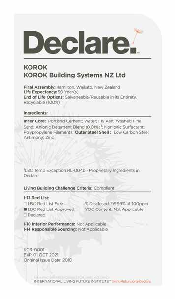
INTRODUCTION

  SUPERIOR FIRE AND ACOUSTIC PERFORMANCE WITH CLIP-TOGETHER SIMPLICITY

           •   BRANZ appraised
           •   Roll formed galvanised steel or colour
               steel outer shell
           •   Lightweight with an aerated concrete
               core
           •   Fire ratings up to -/240/240
           •   Acoustic ratings up to STC 76
           •   Panels interlock with clip-together
               simplicity for rapid installation
           •   Can be dismantled and reassembled to
               accommodate changing requirements
           •   Can be installed horizontally or vertically

When acoustic and fire regulations demand a high                 FIRE PERFORMANCE
performance, no-risk solution, KOROK® will exceed New
Zealand Building Code requirements for internal and             KOROK® delivers proven two-way fire resistance over
external non-load bearing walls simply and cost effectively.    a long period of time. KOROK® has been tested and
                                                                appraised by the Building Research Association of New
Exceptionally strong yet lightweight, the interlocking          Zealand (BRANZ).
panels can be easily erected by a small crew, making
KOROK® much faster to install than conventional wall
systems.
                                                                100% REUSABLE, MINIMUM WASTE
                                                                KOROK® is manufactured in New Zealand and offers unique
Construction using KOROK® allows a building to be made
                                                                benefits in terms of sustainability and environmental
weather resistant much earlier in the construction cycle
                                                                performance:
allowing internal work and finishing to be started sooner.
                                                                •   Walls can be reused by simply dismantling the panels
ACOUSTIC PERFORMANCE                                                and reinstalling them in another location.

KOROK®’s inherent mass and interlocking design gives it         •   The raw components (steel and concrete) are 100%
outstanding acoustic reduction properties making it highly          recyclable.
suitable in buildings where acoustic performance is critical,   •   Panels are custom manufactured to size, minimising
such as cinemas, lecture theatres, apartments, recording            waste at the factory and on the construction site.
studios and industrial/commercial intertenancy situations.
                                                                •   DECLARE - KOROK has Declare Certification for our
The unique interlocking design eliminates the risk of sound         panels, the most accessed sustainability certification
“leaks” between panels, and makes installation much faster          in the building industry https://living-future.org/
and more simple than traditional systems.                           declare-products/korok. See page 35.

KOROK® INTERTENANCY APARTMENTS SYSTEMS www.korok.com 0800 773 777                                                 .1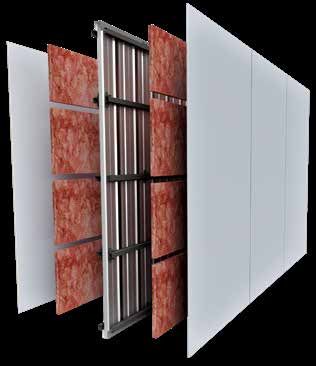
INTRODUCTION
USE ONLY THE CURRENT                                               SCOPE OF USE
SPECIFICATION                                                      New Zealand Building Code (NZBC) compliance
This publication may be superseded by a new publication.           The NZBC sets out both the legal minimum sound
KOROK® Building Systems NZ Ltd accepts no liability for            transmission between tenancies (Clause G6) and minimum
reliance upon publications that have been superseded. If           levels of fire resistance (Clauses C3 and C6). The KOROK®
you are unsure whether this is the current publication, visit      Intertenancy Systems Manual provides guidance on
www.korok.com or call 0800 773 777.                                the specification and construction of systems that will
                                                                   both meet and exceed those minimum levels. However,
This may be freely copied (in full) or reproduced (in full) and
                                                                   designers should consider the comfort of occupants
is available by contacting us at KOROK® on 0800 773 777
                                                                   when selecting a system that will satisfy the occupants’
or info@korok.com, or from www.korok.com
                                                                   expectations when using the space rather than the
                                                                   minimum required by law.
BEWARE OF SUBSTITUTIONS
                                                                   NZBC Clause B1 – Structure
All KOROK® systems have been designed and tested                   The KOROK® Systems meet the requirements for loads
to ensure they are suitable for New Zealand conditions             arising from self-weight, earthquake, wind, impact and
and provide specific resistance to fire and acoustic               creep and shrinkage.
transmission.
                                                                   NZBC Clause B2 – Durability
As such, only tested KOROK® panels and components                  Under normal conditions of dry internal use KOROK®
can be used in the construction of each KOROK® system,             Intertenancy Systems have a serviceable life in excess of
ensuring that the finished wall will meet its performance          50 years and satisfy the requirements of NZBC Clause B2
specification.                                                     – Durability.
                                                                   NZBC Clauses C3 - Fire affecting areas beyond the
PURPOSE                                                            source
KOROK® provide intertenancy systems that physically                KOROK® Intertenancy Systems can be used to
separate spaces, providing secure divisional walls and             provide passive fire protection in accordance with the
intertenancy sound and fire transmission resistance.               requirements of NZBC Clause 3 – Spread of fire

KOROK® supplies separate systems for residential and               NZBC Clause C6 - Structural Stability
apartment intertenancy walls. Please ensure that the               Compliance with (NZBC) Clause C6 ‘ Structural Stability’.
system selected is identified as being appropriate for the         In order to satisfy the requirements of the New Zealand
location it is being installed in.                                 Building Code (clause 6) relating to “structural stability”
                                                                   designers must ensure that KOROK® elements are
                                                                   supported by primary elements that have at least the
                                                                   same fire rating as the KOROK® system that is used.
                                                                   Where the primary elements supporting the KOROK®
                                                                   system are outside the fire cell, there is no requirement
                                                                   to apply the same FRR as the KOROK® system.
                                                                   Notwithstanding, post fire stability requirements of the
                                                                   NZBC must also be satisfied.
                                                                   NZBC Clause G6 – Airborne and Impact Sound
                                                                   KOROK® Intertenancy Systems, both meet and exceed
                                                                   the minimum requirements outlined in NZBC Clause G6.
                                                                   Consideration should be given to both the minimum
                                                                   requirements and the comfort of occupants.

.2                                                   KOROK® INTERTENANCY APARTMENTS SYSTEMS www.korok.com 0800 773 777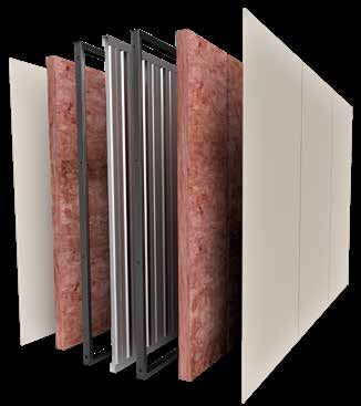
INTRODUCTION
TRANSPORT                                                        STRIPPABLE FILM
Generally the lengths of KOROK® are delivered to site by         KOROK® panels may be coated with a plastic film to
long trailers and articulated trucks. Therefore access to        provide protection during handling and transportation.
and on building sites must be adequate to accommodate            This film has a very short life when exposed to exterior
these types of vehicles.                                         conditions and must be removed immediately after
                                                                 installation.
Off loading and site storage or cranage onto site is the
responsibility of the client and suitable arrangements           It must not be left lying in the sun or at the site for more
should be made prior to delivery.                                than a few hours. Failure to remove the film will lead to
                                                                 difficulties later with its removal.
KOROK® products are packed and protected against
damage during delivery but care must be exercised during
unloading.                                                       CUTTING OF KOROK® PANELS
Lengths must be adequately supported during unloading            Its recommended that KOROK® panels are cut using a
and where packs are broken and panels lifted by hand, care       Hilti DCH300 Electric Concrete Cutter with dust removal
must be taken not to slide or drag the panel and scrape the      system. Hot swarf should not be allowed to contact pre-
finished surfaces of the product.                                painted or galvanized sheet material. Any grinding, welding
                                                                 or drillings carried out above the wall level should be done
                                                                 with the panels appropriately covered to avoid swarf
HANDLING AND STORAGE                                             contact.
KOROK® panels must be stored under clean, dry and
                                                                 Failure to do so will result in unsightly staining of the
ventilated conditions.
                                                                 surface as the metal particles rust or oxidise.
Where it is necessary for KOROK® Panels to be stored
onsite they should be placed away from the building              INSTALLATION
operations, if possible, in the order in which they will be
fixed.                                                           Specific design advice should be sought where KOROK®
                                                                 is to be subject to point loads or other distributed loading
Storage should provide a firm and dry base, protected            other than wind.
from the weather, accidental damage and moisture.
                                                                 Ensure connections between KOROK® panels are
The panels should be stored on bearers no more than              properly made.
2000mm apart. Stack heights are limited to 8 pallets.
                                                                 Ensure connections of KOROK® panels to the structure
Adequate cover must be provided and water must not               are adequate.
lie on or between the panel surfaces, which will cause
staining and degradation of the surface coatings.
                                                                 DEFINITIONS
If pallets become wet the KOROK® panels should without
delay be separated, wiped with a clean cloth and stacked         STC
so that the circulation of air will complete the drying          Sound Transmission Class is derived from an ASTM
process.                                                         standard test procedure which rates the airborne sound
                                                                 transmission loss through building elements such as walls
                                                                 and ceilings. dB loss is measured at a 1/3 octave range
ON SITE HANDLING AND STORAGE                                     between 125Hz and 4000Hz. The minimum requirement
Handle KOROK® panels carefully prior to installation.            for residential Intertenancy is STC 55.
Avoid knocks, bumps and scratches, which may lead to             FRR
maintenance issues later.                                        Fire Resistance Rating is derived from a laboratory furnace
Store KOROK® panels on site flat or in their pallets and         test which gives a value in minutes for Structural adequacy,
ensure that KOROK® panels are dry prior to installation.         Integrity, and Insulation. Depending on design, all three
                                                                 may not be relevant to the building element.
CLEANING
At the completion of the job and at the finish of each day’s
work, it is essential that the completed area be thoroughly
cleaned of all swarf, rivet stems, nails drillings and screws,
etc. normally associated with the installation of metal
panels.

KOROK® INTERTENANCY APARTMENTS SYSTEMS www.korok.com 0800 773 777                                                        .3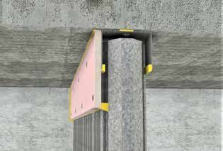
KOROK® APARTMENT
INTERTENANCY
SYSTEMS
KOROK® APARTMENT INTERTENANCY SYSTEMS
TABLE 1 - SYSTEMS SUMMARY TABLE

 SPEC.    STC   FRR         WALL           FRAME                   CAVITY           SYSTEM SUMMARY                                PAGE
 CODE                       THICKNESS*

 KIM01    58    -/60/60     194mm         64mm Steel frame         Minimum          KOROK® 51mm panels (600 Kg/m3 density)         6
                                          one side                 20mm             + 1 layer 13mm GIB® Standard plasterboard
                                                                                    or equivalent each side**
                                          28mm Furring
                                          channel on direct fix
                                          clips the other

 KIM02    57    -/60/60     122mm         28mm Furring             N/A              KOROK® 51mm panels (600 Kg/m3 density)         7
                                          channel on resilient                      + 1 layer 13mm GIB Noiseline® or equivalent
                                          mounts one side                           each side**

 KIM03    59    -/60/60     167mm         28mm Furring             N/A              KOROK® 51mm panels (600 Kg/m3 density)         8
                                          channel on resilient                      + 1 layer 13mm GIB Noiseline® or equivalent
                                          mounts each side                          each side**

 KIM04    59    -/60/60     161mm         64mm Steel frame         Minimum          KOROK® 51mm panels (600 Kg/m3 density)         9
                                          one side                 20mm             + 1 layer 13mm GIB® Standard plasterboard
                                                                                    or equivalent each side**

 KIM05    68    -/60/60     240mm         64mm Steel frame         Minimum          KOROK® 51mm panels (600 Kg/m3 density)        10
                                          each side                86mm             + 1 layer 13mm GIB® Standard plasterboard
                                                                   between          or equivalent each side**
                                                                   the framing.
                                                                   Framing not to
                                                                   touch KOROK®
                                                                   panel

 KIM06    59    -/120/120   188mm         64mm steel frame         Minimum          KOROK® 78mm panels (400 Kg/m3 density)        11
                                          one side                 20mm             + 1 layer 13mm GIB Noiseline® or equivalent
                                                                                    one side + 1 layer 13mm GIB® Standard
                                                                                    plasterboard or equivalent other side**

 KIM07    56    -/120/120   188mm         64mm steel frame         Minimum          KOROK® 78mm panels (400 Kg/m3 density)        12
                                          one side                 20mm             + 1 layer 13mm GIB® Standard plasterboard
                                                                                    or equivalent each side**

 KIM08    61    -/60/60     181mm         64mm steel frame         Minimum          KOROK® 51mm panels (600 Kg/m3 density)        13
                                          one side                 20mm             + 1 layer 13mm USG Boral Multistop4 or
                                                                                    equivalent each side**
                                          16mm Furring
                                          channel on direct fix
                                          clips the other

 KIM09    60    -/60/60     175mm         28mm Furring             N/A              KOROK® 51mm panels (600 Kg/m3 density)        14
                                          channel on BetaFix                        + 1 layer 13mm GIB Noiseline® or equivalent
                                          clips each side                           each side**

 KIM12    61    -/60/60     167mm         64mm steel frame         Minimum          KOROK® 51mm panels (600 Kg/m3 density)        15
                                          one side                 10mm             + 1 layer 13mm USG Boral Multistop4 or
                                                                                    equivalent each side**
                                          16mm Furring
                                          channel directly fixed
                                          the other

 KIM13    64    -/60/60     194mm         64mm steel frame         Minimum          KOROK® 51mm panels (600 Kg/m3 density)        16
                                          one side                 20mm             + 1 layer 13mm USG Boral Multistop4 or
                                                                                    equivalent one side +2 layers 13mm USG
                                          16mm Furring                              Boral Multistop4 or equivalent the other**
                                          channel on direct fix
                                          clips the other

*Nominal thickness
**Acoustic insulation for each system is as per specification sheet

KOROK® INTERTENANCY APARTMENTS SYSTEMS www.korok.com 0800 773 777                                                                 .5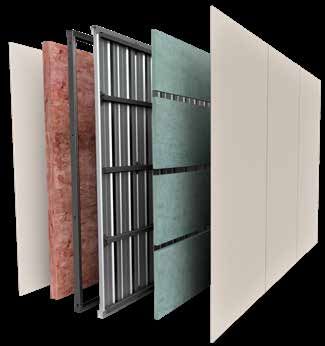
KIM01 FRR -/60/60
 SPEC.   STC    FRR         WALL         FRAME                         CAVITY         SYSTEM SUMMARY
 CODE                       THICKNESS*

 KIM01   58     -/60/60     194mm        64mm Steel frame one side.    Minimum       KOROK® 51mm panels (600 Kg/m3 density) +
                                         28mm Furring channel on       20mm          1 layer 13mm GIB® Standard plasterboard or
                                         direct fix clips the other                  equivalent each side

                                                                                                                  *Nominal thickness
KOROK® PANEL                                                          LINING
KOROK® 51mm panels are located in KOROK® C-track                      Frames are lined with 1 layer of 13mm GIB® Standard
60mm high x 51mm wide x 1.15B.M.T. The KOROK®                         plasterboard or equivalent on each side fixed vertically
C-track is fixed to the structure at 400mm centres max,               with joints over framing one side and on Furring channels
and bedded on a bead of fire rated sealant. KOROK®                    at 600mm maximum centres on the other.
panels must not exceed 5 metres in height.
                                                                      Plasterboard linings are installed to the manufacturers
                                                                      specification. Joints must be stopped.
FRAMING
64mm x 34mm x 0.55B.M.T. steel studs, friction fitted into            SEALANT
C-Section track one side.
                                                                      Beads of fire rated sealant are required around the
Allow a minimum 20mm gap between the framing and the                  perimeter of the KOROK® system.
KOROK® panel.
                                                                      Refer to the installation section of this publication for more
28mm Furring channel at 600mm maximum centres                         information on sealant application.
mounted on direct fix clips on the other.
                                                                      Refer to the KOROK® Components Summary for approved
Framing must be installed as per manufacturer’s                       sealants.
instructions.

ACOUSTIC INSULATION
Acoustic insulation must be either Autex GreenStuf SW75
or Pink Batts R 1.8 or equivalent within the steel stud side
and Autex R0.5 Masonry 20mm Wall Blanket or equivalent
on the Furring channel side.

   KIM01

      60 x 51mm KOROK®
      C-track

      1 layer 13mm GIB®
      Standard plasterboard                                                                              Acoustic Insulation
      or equivalent

      KOROK® 51mm panel                                                                                  1 layer 13mm GIB®
      density 600kg/m3                                                                                   Standard plasterboard
                                                                                                         or equivalent

      Acoustic Insulation

      64mm x 0.55B.M.T.
      steel framing
                                                                                                                     STC
      Gap to framing
      minimum 20mm
                                               Furring channel
                                               on direct fix clips
                                                                                                                     58

.6                                                 KOROK® INTERTENANCY APARTMENTS SYSTEMS www.korok.com 0800 773 777
KIM02 FRR -/60/60
SPEC. STC FRR WALL FRAME CAVITY SYSTEM SUMMARY
CODE THICKNESS*
KIM02 57 -/60/60 122mm 28mm Furring channel on N/A KOROK® 51mm panels (600 Kg/m3 density) + 1 layer of
resilient mounts one side 13mm GIB Noiseline® or equivalent on each side
*Nominal thickness
KOROK® PANEL LINING
KOROK® 51mm panels are located in KOROK® C-track 1 layer of 13mm GIB Noiseline® or equivalent on one side
60mm high x 51mm wide x 1.15B.M.T. The KOROK® fixed vertically over Furring channel and 1 layer of 13mm
C-track is fixed to the structure at 400mm centres max, GIB Noiseline® or equivalent the other.
and bedded on a bead of fire rated sealant. KOROK®
Plasterboard linings are installed to the manufacturers
panels must not exceed 5 metres in height.
specification. Joints must be stopped.
FRAMING SEALANT
28mm Furring channel at 600mm maximum centres one
Beads of fire rated sealant are required around the
side mounted on ST001 Resilient Mounts fixed to KOROK®
perimeter of the KOROK® system.
panel joints at 1000mm centres.
Refer to the installation section of this publication for more
Framing must be installed as per manufacturer’s
information on sealant application.
instructions.
Refer to the KOROK® Components Summary for approved
ACOUSTIC INSULATION sealants.
Acoustic insulation must be Autex Masonry Wall Blanket
45mm R1.3 or equivalent on the Furring channel side.
KIM02
60 x 51 KOROK®
C-track
1 layer 13mm GIB
Noiseline® or equivalent
fixed directly to KOROK® Autex Masonry Wall
panel Blanket 45mm R1.3 or
equivalent
KOROK® 51mm panel
density 600kg/m3 1 layer 13mm
GIB Noiseline® or
equivalent
Furring channels
at 600mm centres
on ST001 Resilient
Mounts fixed to
panel joints at STC
1000mm centres
57
KOROK® INTERTENANCY APARTMENTS SYSTEMS www.korok.com 0800 773 777 .7KIM03 FRR -/60/60
SPEC. STC FRR WALL FRAME CAVITY SYSTEM SUMMARY
CODE THICKNESS*
KIM03 59 -/60/60 167mm 28mm Furring channel on N/A KOROK® 51mm panels (600 Kg/m3 density) + 1 layer
resilient mounts each side 13mm GIB Noiseline® or equivalent each side
*Nominal thickness
KOROK® PANEL LINING
KOROK® 51mm panels are located in KOROK® C-track 1 layer of 13mm GIB Noiseline® or equivalent on each side
60mm high x 51mm wide x 1.15B.M.T. The KOROK® fixed vertically.
C-track is fixed to the structure at 400mm centres max,
Plasterboard linings are installed to the manufacturers
and bedded on a bead of fire rated sealant. KOROK®
specification. Joints must be stopped.
panels must not exceed 5 metres in height.
FRAMING SEALANT
Beads of fire rated sealant are required around the
28mm Furring channel at 600mm maximum centres
perimeter of the KOROK® system.
mounted on ST001 Resilient Mounts fixed to KOROK®
panel joints at 1000mm centres each side. Refer to the installation section of this publication for more
information on sealant application.
Framing must be installed as per manufacturer’s
instructions. Refer to the KOROK® Components Summary for approved
sealants.
ACOUSTIC INSULATION
Acoustic insulation must be Autex Masonry Wall Blanket
45mm R1.3 or equivalent each side.
KIM03
60 x 51mm
KOROK® C-track
1 layer 13mm
GIB Noiseline® or
equivalent
1 layer 13mm
Autex Masonry Wall GIB Noiseline® or
Blanket 45mm R1.3 equivalent
or equivalent
KOROK® 51mm panel Autex Masonry Wall
density 600kg/m3 Blanket 45mm R1.3
or equivalent
Furring channels
at 600mm centres
on ST001 Resilient
Mounts fixed to STC
59
KOROK® panel joints
at 1000mm centres
.8 KOROK® INTERTENANCY APARTMENTS SYSTEMS www.korok.com 0800 773 777KIM04 FRR -/60/60
SPEC. STC FRR WALL FRAME CAVITY SYSTEM SUMMARY
CODE THICKNESS*
KIM04 59 -/60/60 161mm 64mm Steel Minimum KOROK® 51mm panels (600 Kg/m3 density) + 1 layer 13mm
frame one side 20mm GIB® Standard plasterboard or equivalent each side
*Nominal thickness
KOROK® PANEL LINING
KOROK® 51mm panels are located in KOROK® C-track 1 layer of 13mm GIB® Standard plasterboard or equivalent
60mm high x 51mm wide x 1.15B.M.T. The KOROK® on each side fixed vertically with joints over framing one
C-track is fixed to the structure at 400mm centres max, side and direct-fixed the other.
and bedded on a bead of fire rated sealant. KOROK®
Plasterboard linings are installed to the manufacturers
panels must not exceed 5 metres in height.
specification. Joints must be stopped.
FRAMING SEALANT
64mm x 34mm x 0.55B.M.T. steel studs, friction fitted into
Beads of fire rated sealant are required around the
C-Section track 64mm x 30mm x 0.55B.M.T.
perimeter of the KOROK® system.
Allow a minimum 20mm gap between the framing and the
Refer to the installation section of this publication for more
KOROK® panel.
information on sealant application.
Framing must be installed as per manufacturer’s
Refer to the KOROK® Components Summary for approved
instructions.
sealants.
ACOUSTIC INSULATION
Acoustic insulation must be either Autex GreenStuf SW75
or Pink Batts R 1.8 or equivalent within the steel stud side.
KIM04
60 x 51mm
KOROK® C-track
1 layer 13mm GIB®
Acoustic Insulation
Standard plasterboard
or equivalent
1 layer 13mm GIB®
Standard plasterboard
KOROK® 51mm panel or equivalent
density 600kg/m3
Gap to framing
minimum 20mm
STC
59
64mm x 0.55B.M.T.
steel framing
KOROK® INTERTENANCY APARTMENTS SYSTEMS www.korok.com 0800 773 777 .9KIM05 FRR -/60/60
SPEC. STC FRR WALL FRAME CAVITY SYSTEM SUMMARY
CODE THICKNESS*
KIM05 68 -/60/60 240mm 64mm Steel Minimum 86mm overall KOROK® 51mm panels (600 Kg/m3
frame each side between the framing. Framing density) + 1 layer 13mm GIB® Standard
not to touch KOROK® panel plasterboard or equivalent each side
*Nominal thickness
KOROK® PANEL LINING
KOROK® 51mm panels are located in KOROK® C-track 1 layer of 13mm GIB® Standard plasterboard or equivalent
60mm high x 51mm wide x 1.15B.M.T. The KOROK® on each side fixed vertically with all joints over framing.
C-track is fixed to the structure at 400mm centres max,
Plasterboard linings are installed to the manufacturers
and bedded on a bead of fire rated sealant. KOROK®
specification. Joints must be stopped.
panels must not exceed 5 metres in height.
FRAMING SEALANT
Beads of fire rated sealant are required around the
64mm x 34mm x 0.55B.M.T. steel studs, friction fitted into
perimeter of the KOROK® system.
C-Section track 64mm x 30mm x 0.55B.M.T.
Refer to the installation section of this publication for more
Cavity must be 86mm overall between the framing.
information on sealant application.
Framing not to touch KOROK® panel.
Refer to the KOROK® Components Summary for approved
Framing must be installed as per manufacturer’s
sealants.
instructions.
ACOUSTIC INSULATION
Acoustic insulation must be either Autex GreenStuf SW75
or Pink Batts R 1.8 or equivalent each side.
KIM05
60 x 51mm
KOROK® C-track
1 layer 13mm GIB®
Standard plasterboard or
Acoustic Insulation
equivalent
1 layer 13mm
KOROK® 51mm panel GIB® Standard
density 600kg/m3 plasterboard or
equivalent
Acoustic Insulation
64mm x 0.55B.M.T.
steel framing
STC
Gap between framing minimum 86mm
68
.10 KOROK® INTERTENANCY APARTMENTS SYSTEMS www.korok.com 0800 773 777KIM06 FRR -/120/120
SPEC. STC FRR WALL FRAME CAVITY SYSTEM SUMMARY
CODE THICKNESS*
KIM06 59 -/120/120 188mm 64mm steel Minimum 20mm KOROK® 78mm panels (400 Kg/m3 density) + 1 layer 13mm
frame one side GIB Noiseline® or equivalent one side + 1 layer 13mm GIB®
Standard or equivalent other side
*Nominal thickness
KOROK® PANEL LINING
KOROK® 78mm panels are located in KOROK® C-track 1 layer of 13mm GIB® Standard on one side and one layer
60mm high x 80mm wide x 1.15B.M.T. The KOROK® of 13mm GIB Noiseline® or equivalent on the other, fixed
C-track is fixed to the structure at 400mm centres max, vertically with joints over framing one side and direct-fixed
and bedded on a bead of fire rated sealant. the other.
FRAMING Plasterboard linings are installed to the manufacturers
64mm x 34mm x 0.55B.M.T. steel studs, friction fitted into specification. Joints must be stopped.
C-Section track 64mm x 30mm x 0.55B.M.T.
Allow a minimum 20mm gap between the framing and the
SEALANT
KOROK® panel. Beads of fire rated sealant are required around the
perimeter of the KOROK® system.
Framing must be installed as per manufacturer’s
instructions. Refer to the installation section of this publication for more
information on sealant application.
ACOUSTIC INSULATION Refer to the KOROK® Components Summary for approved
sealants.
Acoustic insulation must be either Autex GreenStuf SW75
or Pink Batts R 1.8 or equivalent within the steel stud side.
KIM06
60 x 80mm
KOROK® C-track
1 layer 13mm GIB®
Standard plasterboard
or equivalent
1 layer 13mm
GIB Noiseline® or
KOROK® 78mm panel equivalent
density 400kg/m3
Acoustic insulation
STC
Gap to framing minimum 20mm
64mm x 0.55B.M.T. steel framing 59
KOROK® INTERTENANCY APARTMENTS SYSTEMS www.korok.com 0800 773 777 .11KIM07 FRR -/120/120
SPEC. STC FRR WALL FRAME CAVITY SYSTEM SUMMARY
CODE THICKNESS*
KIM07 56 -/120/120 188mm 64mm steel Minimum KOROK® 78mm panels (400 Kg/m3 density) + 1 layer 13mm
frame one side 20mm GIB® Standard plasterboard or equivalent each side
*Nominal thickness
KOROK® PANEL LINING
KOROK® 78mm panels are located in KOROK® C-track 1 layer of 13mm GIB® Standard plasterboard or equivalent
60mm high x 80mm wide x 1.15B.M.T. The KOROK® each side fixed vertically with joints over framing one side
C-track is fixed to the structure at 400mm centres max, and direct-fixed the other.
and bedded on a bead of fire rated sealant.
Plasterboard linings are installed to the manufacturers
specification. Joints must be stopped.
FRAMING
64mm x 34mm x 0.55B.M.T. steel studs, friction fitted into SEALANT
C-Section track 64mm x 30mm x 0.55B.M.T.
Beads of fire rated sealant are required around the
Allow a minimum 20mm gap between the framing and the perimeter of the KOROK® system.
KOROK® panel.
Refer to the installation section of this publication for more
Framing must be installed as per manufacturer’s information on sealant application.
instructions.
Refer to the KOROK® Components Summary for approved
sealants.
ACOUSTIC INSULATION
Acoustic insulation must be either Autex GreenStuf SW75
or Pink Batts R 1.8 or equivalent within the steel stud side.
KIM07
60 x 80mm
KOROK® C-track
1 layer 13mm GIB® Acoustic Insulation
Standard plasterboard
or equivalent
1 layer 13mm GIB®
Standard plasterboard
KOROK® 78mm panel or equivalent
density 400kg/m3
Gap to framing
minimum 20mm STC
64mm x 0.55B.M.T.
steel framing 56
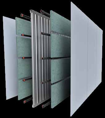
.12 KOROK® INTERTENANCY APARTMENTS SYSTEMS www.korok.com 0800 773 777KIM08 FRR -/60/60
SPEC. STC FRR WALL FRAME CAVITY SYSTEM SUMMARY
CODE THICKNESS*
KIM08 61 -/60/60 181mm 64mm Steel frame one side. Minimum KOROK® 51mm panels (600 Kg/m3 density) + 1 layer
20mm 13mm USG Boral Multistop4 or equivalent each side
16mm Furring channel on
direct fix clips the other
*Nominal thickness
KOROK® PANEL ACOUSTIC INSULATION
KOROK® 51mm panels are located in KOROK® C-track Acoustic insulation must be Bradford 75mm
60mm high x 51mm wide x 1.15B.M.T. The KOROK® ACOUSTIGARD 14kg/m3 or equivalent, within the steel
C-track is fixed to the structure at 400mm centres max, stud side.
and bedded on a bead of fire rated sealant. KOROK®
panels must not exceed 5 metres in height. LINING
1 layer of 13mm USG Boral Multistop4 or equivalent each
FRAMING side.
One side, 64mm x 34mm x 0.55B.M.T. steel studs, friction
Plasterboard linings are installed to the manufacturers
fitted into C-Section track 64mm x 30mm x 0.55B.M.T.
specification. Joints must be stopped.
Allow a minimum 20mm gap between the framing and the
KOROK® panel. SEALANT
Other side, 16mm Furring channel at 600mm maximum Beads of fire rated sealant are required around the
centres on direct fix clips, fixed to the KOROK® panel at perimeter of the KOROK® system.
maximum 1000mm centres. Refer to the installation section of this publication for more
Framing must be installed as per manufacturer’s information on sealant application.
instructions. Refer to the KOROK® Components Summary for approved
sealants.
KIM08
60 x 51mm
KOROK® C-track
1 layer 13mm USG
16mm Furring channel
Boral Multistop4 or
on direct fix clips
equivalent
1 layer 13mm USG
Boral Multistop4 or
KOROK® 51mm panel equivalent
density 600kg/m3
Acoustic Insulation
64mm x 0.55B.M.T.
steel framing STC
Gap to framing
minimum 20mm 61
KOROK® INTERTENANCY APARTMENTS SYSTEMS www.korok.com 0800 773 777 .13KIM09 FRR -/60/60
SPEC. STC FRR WALL FRAME CAVITY SYSTEM SUMMARY
CODE THICKNESS*
KIM09 60 -/60/60 175mm 28mm Furring channel on N/A KOROK® 51mm panels (600 Kg/m3 density) + 1
BetaFix clips each side layer 13mm GIB Noiseline® or equivalent each side
*Nominal thickness
KOROK® PANEL LINING
KOROK® 51mm panels are located in KOROK® C-track 1 layer of 13mm GIB Noiseline® or equivalent on each side
60mm high x 51mm wide x 1.15B.M.T. The KOROK®
C-track is fixed to the structure at 400mm centres max, Plasterboard linings are installed to the manufacturers
and bedded on a bead of fire rated sealant. KOROK® specification. Joints must be stopped.
panels must not exceed 5 metres in height.
SEALANT
FRAMING Beads of fire rated sealant are required around the
28mm Furring channel at 600mm maximum centres perimeter of the KOROK® system.
on each side, mounted on BetaFix clips directly fixed to Refer to the installation section of this publication for more
KOROK® panel at maximum 600mm centres. information on sealant application.
Framing must be installed as per manufacturer’s Refer to the KOROK® Components Summary for approved
instructions. sealants.
ACOUSTIC INSULATION
Acoustic insulation must be Pink Batts R 1.2 50mm 12.8
kg/m3 or equivalent each side.
KIM09
60 x 51mm
KOROK® C-track
1 layer 13mm
GIB Noiseline® or
Acoustic Insulation
equivalent
1 layer 13mm
KOROK® 51mm panel GIB Noiseline® or
density 600kg/m3 equivalent
Acoustic Insulation
STC
28mm Furring channel
on BetaFix clips 60
.14 KOROK® INTERTENANCY APARTMENTS SYSTEMS www.korok.com 0800 773 777KIM12 FRR -/60/60
SPEC. STC FRR WALL FRAME CAVITY SYSTEM SUMMARY
CODE THICKNESS*
KIM12 61 -/60/60 167mm 64mm steel frame one side Minimum KOROK® 51mm panels (600 Kg/m3
10mm density) + 1 layer 13mm USG Boral
16mm Furring channel directly fixed the other Multistop4 or equivalent each side
*Nominal thickness
KOROK® PANEL ACOUSTIC INSULATION
KOROK® 51mm panels are located in KOROK® C-track Acoustic insulation must be Bradford 75mm
60mm high x 51mm wide x 1.15B.M.T. The KOROK® ACOUSTIGARD 14kg/m3 or equivalent within the steel stud
C-track is fixed to the structure at 400mm centres max, side.
and bedded on a bead of fire rated sealant. KOROK®
panels must not exceed 5 metres in height. LINING
1 layer of 13mm USG Boral Multistop4 or equivalent each
FRAMING side.
64mm x 34mm x 0.55B.M.T. steel studs, friction fitted into
C-Section track 64mm x 30mm x 0.55B.M.T. Plasterboard linings are installed to the manufacturers
specification. Joints must be stopped.
Allow a minimum 10mm gap between the framing and the
KOROK® panel. SEALANT
16mm Furring channel at 600mm maximum centres on Beads of fire rated sealant are required around the
one side directly fixed to KOROK® panel (no clips). perimeter of the KOROK® system.
Framing must be installed as per manufacturer’s Refer to the installation section of this publication for more
instructions. information on sealant application.
Refer to the KOROK® Components Summary for approved
sealants.
KIM12
60 x 51mm
KOROK® C-track
1 layer 13mm USG
16mm Furring channel
Boral Multistop4 or
equivalent
1 layer 13mm USG
Boral Multistop4 or
KOROK® 51mm panel equivalent
density 600kg/m3
Acoustic Insulation
64mm x 0.55B.M.T.
steel framing STC
Gap to framing
minimum 10mm
61
KOROK® INTERTENANCY APARTMENTS SYSTEMS www.korok.com 0800 773 777 .15KIM13 FRR -/60/60
SPEC. STC FRR WALL FRAME CAVITY SYSTEM SUMMARY
CODE THICKNESS*
KIM13 64 -/60/60 194mm 64mm steel frame one side Minimum KOROK® 51mm panels (600 Kg/m3 density) + 1 layer
20mm 13mm USG Boral Multistop4 or equivalent one side + 2
16mm Furring channel on layers of USG Boral Multistop4 or equivalent the other
237 direct fix clips the other side
*Nominal thickness
KOROK® PANEL ACOUSTIC INSULATION
KOROK® 51mm panels are located in KOROK® C-track Acoustic insulation must be Bradford 75mm
60mm high x 51mm wide x 1.15B.M.T. The KOROK® ACOUSTIGARD 14kg/m3 or equivalent within the steel stud
C-track is fixed to the structure at 400mm centres max, side.
and bedded on a bead of fire rated sealant. KOROK®
panels must not exceed 5 metres in height. LINING
1 layer of 13mm USG Boral Multistop4 or equivalent
FRAMING one side and 2 layers of 13mm USG Boral Multistop4 or
64mm x 34mm x 0.55B.M.T. steel studs, friction fitted into equivalent on the other side.
C-Section track 64mm x 30mm x 0.55B.M.T.
Plasterboard linings are installed to the manufacturers
Allow a minimum 20mm gap between the framing and the specification. Joints must be stopped.
KOROK® panel.
16mm Furring channel at 600mm maximum centres on the SEALANT
other side mounted on 237 clips fixed to KOROK® panel Beads of fire rated sealant are required around the
joints at maximum 1000mm centres. perimeter of the KOROK® system.
Framing must be installed as per manufacturer’s Refer to the installation section of this publication for more
instructions. information on sealant application.
Refer to the KOROK® Components Summary for approved
sealants.
KIM13
60 x 51mm
KOROK® C-track
2 layers 13mm USG
16mm Furring channel
Boral Multistop4 or
on 237 clips
equivalent
1 layer 13mm USG
Boral Multistop4 or
KOROK® 51mm panel equivalent
density 600kg/m3
Acoustic Insulation
64mm x 0.55B.M.T.
steel framing
STC
Gap to framing
minimum 20mm
64
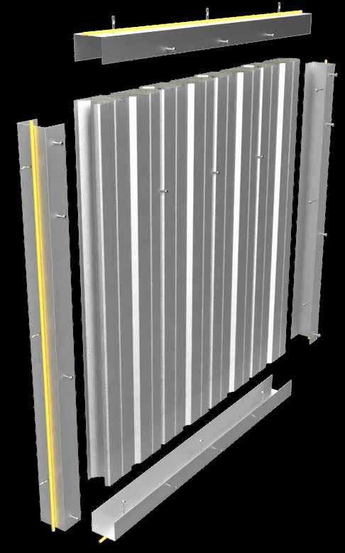
.16 KOROK® INTERTENANCY APARTMENTS SYSTEMS www.korok.com 0800 773 777APARTMENT INTERTENANCY SYSTEMS INSTALLATION
C-track or Angle sections
are fixed to structural
elements (steelwork) at
400mm centres with Hilti
X-ENP-19 L15 fasteners
When fixing C-track
or Angle sections to
concrete, use 6.5 x 32
Rawl Mushroom spikes
or Hilti DBZ 6/4.5 x 32mm
at 400mm centres
The C-track or Angle
section must have a
continuous bead of fire
rated sealant between
the track and the
structure to which it is
fixed
Panels are fixed together
with Wafer Tek 10g - 16
x 16mm screws. For
centres see Step 12
Corner joints must be
sealed with fire rated
sealant (see component
summary for specifics)
KOROK® panels are
fixed to the C-track with
Wafer Tek 10g - 16 x
16mm screws both sides
(400mm centres)
KOROK® panels are fixed
to the top and bottom
C-track with Wafer Tek
10g - 16 x 16mm screws
at 250mm centres both
sides
KOROK® INTERTENANCY APARTMENTS SYSTEMS www.korok.com 0800 773 777 .17APARTMENT INTERTENANCY SYSTEMS INSTALLATION VERTICAL INSTALLATION 1 Vertical installation of the KOROK® panels requires the C-track to be fixed to the supporting structure, e.g. walls, columns, portals, soffits and slabs. Plan your setout. 2 To ensure the C-track is sealed to the structure, a continuous bead of fire rated sealant is run around the perimeter before the C-track or Angle sections are laid and fixed. Or the sealant can be applied directly to the C-track before fixing in place. 3 Using a masonry drill bit, pre-drill the C-track at 400mm centres. 4 Then use the fixings to secure the C-track. .18 KOROK® INTERTENANCY APARTMENTS SYSTEMS www.korok.com 0800 773 777
APARTMENT INTERTENANCY SYSTEMS INSTALLATION

5         If the surrounding surface is uneven or
if you’re not sure you have a good seal, add a
continuous bead of fire rated sealant around the
perimeter of the C-track where it contacts the
surrounding surface.

6         KOROK® panels must be cut 20mm shorter
than the structural opening measurement to allow
for fitting.
Pull back a 300mm section of the strippable film on
the ends of the panels before placing the panels in
to the C-track.
Ensure that the first panel is plumbed vertical after
fitting into the C-track. Screw fix the panel into
place to the C-track.
Subsequent panels are placed in a tilt and snap
action.

7         Ensure the tongue and groove are
fully locked to maintain the fire and acoustic
performance. Remove strippable film at the end of
each day’s work.

8       CUTTING OF KOROK® PANELS
KOROK® panels can be cut to length and width
with the use of a reciprocating saw or a radial saw
with dust extraction. Diamond cutting discs are
recommended for radial saws.
Where KOROK® panels are trimmed to width, the
cut edge of the panel is fitted into the C-track
and so is always the last panel abutting the wall
or column. The panel is then sealed and fixed in
position as usual.

KOROK® INTERTENANCY APARTMENTS SYSTEMS www.korok.com 0800 773 777   .19
APARTMENT INTERTENANCY SYSTEMS INSTALLATION
LAST PANEL

9        Stop short of the end vertical KOROK®
C-track by approximately 1 metre and cut out a
600mm Angle section from the top and bottom
C-track.
Plan ahead and make an allowance for a 50mm
overlap onto the panels installed prior to the
last remaining two panels.

10        Cut your end panel (the last panel) ensuring
that a distance of 500mm remains between panels
for the last two panels to be squeezed into position.

                                                                                                        m
                                                                                                     0m
                                                                                                   60

11      Once the final two panels are in position,
simply replace the Angle and fix to panels. Screw
the C-track and Angle sections to the panels in the
normal fashion.

11a     When using 51mm KOROK panels seal the
3 close-off panel joints with fire rated sealant to
one side.

.20                                          KOROK® INTERTENANCY APARTMENTS SYSTEMS www.korok.com 0800 773 777
APARTMENT INTERTENANCY SYSTEMS INSTALLATION 12 Panels must be screwed together into every panel joint as per the vertical centres in Table 2 below. TABLE 2 - FASTENINGS Panel Panel Max. Wall Panel to Panel Max. Sides KOROK Wall System or similar Notes: Thickness Orientation Height (m) Centres (mm) (mm) 51 Vertical 5m 1000 one KIM01,02,03,04,05,08,09,12,13 Measured from floor level 78 Vertical 6m 1000 one KIM06, KIM07 Measured from floor level C-TRACK C-track is fixed to the KOROK® panels at 400mm centres both sides on the vertical C-track and 250mm centres both sides on the horizontal C-track. At corners where two lengths of KOROK® C-track intersect, the two pieces must be fixed to each other with 1 Wafer Tek 10g - 16 x 16mm screw. KOROK® INTERTENANCY APARTMENTS SYSTEMS www.korok.com 0800 773 777 .21
APARTMENT INTERTENANCY SYSTEMS INSTALLATION

13      Remove any remaining plastic film and
then apply a continuous bead of fire rated sealant
between the KOROK® C-track and the KOROK®
panels as indicated by the yellow line.

14      Fire rated sealant details for top and sides.

.22                                          KOROK® INTERTENANCY APARTMENTS SYSTEMS www.korok.com 0800 773 777
APARTMENT INTERTENANCY SYSTEMS INSTALLATION

15     Using Angle as an alternative to C-track.

 FINAL CHECK
 At the completion of the job and at the finish of each day’s work, it is essential that the completed area be
 thoroughly cleaned of all swarf, rivet stems, nails, drillings and screws etc. normally associated with the
 installation of metal KOROK® panels. Remove any remaining strippable film, check all fixings are correctly
 installed, all fire and acoustic rated sealant is applied correctly.

KOROK® INTERTENANCY APARTMENTS SYSTEMS www.korok.com 0800 773 777                                   .23
APARTMENT INTERTENANCY SYSTEMS INSTALLATION
HEAD TRACK PROTECTION
GIB Fyreline® or equivalent PROTECTED HEAD TRACK

GIB Fyreline® or equivalent 13mm x 120mm strip
with fire rated sealant is fixed at 250mm centres
top and bottom, using 32mm x 16G drywall screws.

METAL FLASHING PROTECTED HEAD TRACK

KOROK® fire flashing is fixed to the panels at
250mm centres, using Wafer Tek 10 x 16mm
screws.

.24                                         KOROK® INTERTENANCY APARTMENTS SYSTEMS www.korok.com 0800 773 777
TABLE 3 - KOROK® FASTENERS SPACINGS

                     KOROK®                                                                       Panel to
                               Panel                                                                                            Panel                Panel
                     Wall                Panel       Maximum Maximum Wall Span/                   Panel                   Tek                                   Sides of    Tek
Use                                                                                                            Sides                                 Face or                          Notes:
                     System or Thickness Orientation Wall Height Width (m)                        Maximum                 Screw Perpendicular                   C-track     Screw
                     similar   (mm)                  (m)                                          centres (mm)                  to C-track (mm)      Joint

                     KIM01 to
Intertenancy -       KIM05,                                                                                                                                                           Measured from
                                  51           Vertical      5m                                   1000            one     10-16 250                  Face       Both        10-16
Apartments           KIM08 to                                                                                                                                                         floor level
                     KIM13

Intertenancy -       KIM06 to                                                                                                                                                         Measured from
                                  78           Vertical      6m                                   1000            one     10-16 250                  Face       Both        10-16
Apartments           KIM07                                                                                                                                                            floor level

NOTES
1. For C-track running parallel to the panels, 10-16 Tek screw fixings at 400mm centres are used each side.
2. 78mm Panel Properties - These span tables are based on ambient conditions. When used as part of a fire rated system, the maximum unsupported vertical span of the KOROK® panels is 6.0 metres and the
   maximum unsupported horizontal span is 5.0 metres. Greater spans are subject to specific engineering design and/or fire engineering assessment.
3.   51mm Panel Properties - These span tables are based on ambient conditions. When used as part of a fire rated system, the maximum unsupported span of the KOROK panels is 5.0 metres vertical or 4.0
     metres horizontal. Greater unsupported spans will require specific FRR design.

KOROK® INTERTENANCY APARTMENTS SYSTEMS www.korok.com 0800 773 777                                                                                                                              .25
PANEL PROPERTIES
KOROK® PANELS REFERENCES
KOROK® panels are roll-formed from zinc-coated The following references including standards and
steel strips. The steel from which the shells are codes of practice govern the manufacture of
manufactured conforms to AS1397: 2011. components, use and design and installation of
KOROK® systems.
Steel shells have a base metal thickness of 0.4 mm
B.M.T. with a Z275 zinc coating. These panels have
an aerated concrete core and weigh nominally 10.2 MANUFACTURERS DOCUMENTS
kg per lineal metre.
Refer to KOROK® Systems Manuals.
KOROK® panels have 250 mm coverage when
• Autex® Insulation Data Sheets
installed.
• GIB® Site Guide
LOADING COMBINATIONS • GIB® Fire Rated Systems
All loading combinations are in accordance with • Penetrations and closures in GIB® Fire Rated
AS/NZS 1170.0:2002. Systems
• GIB® Noise Control Systems
GENERAL DESIGN NOTES • Hilti® New Zealand Technical Manual
The designs specified in this manual have been
• Pink® Batts® Data Sheets
carried out in accordance with AS/NZS1170 and
laboratory testing carried out by BRANZ Limited. • Powers Fasteners Specification & Design Manual
The tables and charts are prepared for the use • Rondo® Steel Stud & Tracks Installation Manual
of KOROK® in wall applications i.e. floor systems
• USG® Drywall Steel Stud & Track System
cannot be modelled from the safe load tables
in this manual. Interpolation of the tables is • USG® Boral Plasterboard Installation Manual NZ
acceptable.
STANDARDS
NZS 2589.1-2017
Gypsum Linings in residential
and light commercial
construction.
AS/NZS 1170.0-2002
Structural design actions. Part 0:
General Principles
NZS 7202-1986
250 mm
292 mm
288 mm
Part 1 Specification for gap
filling adhesives
AS 4072.1-2005
Components for the protection
of openings in fire-resistant
separating elements
AS 1530.4-2014
Methods for fire tests on
building materials, components
Gen 2
and structures 51 mm Gen 1
78 mm 78 mm
.26 KOROK® INTERTENANCY APARTMENTS SYSTEMS www.korok.com 0800 773 777KOROK® PANEL PROPERTIES: 78MM 400KG/M3
KOROK® PANEL PROPERTIES USE OF TABLES
• Base Metal Thickness 0.4 mm B.M.T. 1. These Span Tables are based on ambient conditions.
• Mass kg per lineal metre 10.2 nominal 2. When used as part of a fire rated system, the maximum
unsupported vertical span of the KOROK® 78 mm panel
• Mass kg/m2 40.8 nominal
is 6.0 metres. The maximum unsupported horizontal
EI 60 kNm2 per panel (bending stiffness, minor axis) span of the KOROK® 78 mm panel is 5.0 metres. Greater
spans or walls where additional load carrying capacity is
EI 387 kNm2 per panel (bending stiffness, major axis)
required are subject to specific engineering design and/
EA 4060 kN per panel (axial stiffness) or fire engineering assessment.
GJ 583 kNm2 per panel (torsional stiffness) 3. Shelf loading requires specific engineering design.
4. Determine the loads on the KOROK® in accordance with
VERTICAL SPAN WALLS AS/NZS 1170.0.
• Maximum bending moment / panel 1.43 kNm (ULS) 5. Use Table 5 - Horizontal Span to ensure that walls
spanning horizontally can carry the loads previously
• Maximum axial end crush force / panel 25 kN (ULS)
calculated. Use Table 6 - Vertical Span to ensure that
3.4 kN (SLS)
walls spanning vertically can carry the loads previously
• Maximum horizontal reaction (crushing on flat) / panel calculated. Interpolation of points in the tables is
8.9 kN (ULS) 3.1 kN (SLS) allowed.
6. The Tables have been generated for a range of
HORIZONTAL SPAN WALLS deflection limits i.e. Span/150, Span/200, Span/250,
Span/300 in both the vertical and horizontal KOROK®
• Maximum bending moment / panel 1.43 kNm (ULS)
panel configurations.
• Maximum axial edge crush force per unit length
7. The walls must be checked for both ultimate limit state
17 kN/m (ULS) 6k N/m (SLS)
(ULS) loading and serviceability limit state (SLS) loading.
• Maximum horizontal reaction / panel 8.9 kN (ULS)
8. Vertical Span Tables have been generated to a
3.1 kN (SLS)
maximum unsupported span of 8.0 metres height.
THERMAL RESISTANCE 9. Horizontal Span Tables have been generated based on
a 14.0 metres high wall.
• R Value 0.30 (m2K)/W
10. For horizontal panel unsupported spans over 5.0
• U Value 3.2 W/(m2K) metres, for maximum wall heights please contact us at
KOROK® on 0800 773 777.
DEFINITIONS
SUPPORTING STRUCTURES
ULS: Value shown is for Ultimate Limit State loading
KOROK® walls must be supported. The supporting
SLS: Value shown is for Serviceability Limit State loading
structures themselves must be specifically designed to
carry the load of the KOROK® walls.
The fastener strengths shown in this section may be
used to design the connections. Maximum spacing of
fasteners is shown on installation information.
INSTALLATION NOTE
All KOROK® C-track to structure, KOROK® C-track to
KOROK®, and KOROK® to KOROK® panel connections
shall be in accordance with details specified in this
manual unless specified otherwise by the Project
Engineer.
KOROK® INTERTENANCY APARTMENTS SYSTEMS www.korok.com 0800 773 777 .27KOROK® PANEL PROPERTIES: 78MM 400KG/M3
TABLE 4 - SHEAR STRENGTH PER FASTENER FOR THE FOLLOWING CONNECTIONS
DESIGN DESIGN
CONNECTION LOAD DIRECTION TYPE STRENGTH STRENGTH
(KN) ULS (KN) SLS
Panel to panel In-plane 10x16 galvanised Steeltite wafer head screws 1.01 0.83
Panel sides to C-track In-plane 10x16 galvanised Steeltite wafer head screws 0.95 0.78
Panel sides to C-track Out-of-plane 10x16 galvanised Steeltite wafer head screws 0.91 0.74
Panel ends to C-track In-plane 10x16 galvanised Steeltite wafer head screws 0.91 0.74
Panel ends to C-track Out-of-plane 10x16 galvanised Steeltite wafer head screws 2.21 0.77
C-track to concrete In-plane 6.5x32 Rawl Mushroom spikes 7.84 2.27
C-track to concrete Out-of-plane 6.5x32 Rawl Mushroom spikes 7.84 2.27
C-track to steel support In-plane Hilti® X-ENP-10 L15 Nails 4.32 2.31
C-track to steel support Out-of-plane Hilti® X-ENP-10 L15 Nails 4.32 2.31
KOROK® aluminium Out-of-plane Hex Head Type 17 14g x 35mm screws 0.92 0.92
bracket to panel joint
TABLE 5 - HORIZONTAL SPAN TABLE 6 - VERTICAL SPAN
SLS SLS SLS SLS SLS SLS SLS SLS
SPAN ULS DESIGN DESIGN DESIGN DESIGN SPAN ULS DESIGN DESIGN DESIGN DESIGN
(M) DESIGN L/150 L/200 L/250 L/300 (M) DESIGN L/150 L/200 L/250 L/300
2 10.05 9 7.7 6.7 2 10.05 9.05 7.75 6.77
2.5 7.3 6.02 4.94 4.2 3.64 2.5 7.3 6.05 4.95 4.2 3.64
3 5.04 3.7 3 2.5 2.17 3 5.04 3.7 3 2.53 2.18
3.5 3.7 2.42 1.95 1.63 1.39 3.5 3.7 2.42 1.96 1.64 1.4
4 2.82 1.67 1.34 1,1 0.94 4 2.82 1.68 1.34 1.12 0.95
4.5 1.94 1.19 0.94 0.78 0.66 4.5 2.23 1.21 0.96 0.79 0.67
5 1.37 0.88 0.69 0.56 0.47 5 1.79 0.9 0.71 0.58 0.49
6 0.72 0.51 0.39 0.32 0.26 6 1.22 0.54 0.42 0.34 0.28
7 0.38 0.31 0.23 0.19 0.15 7 0.89 0.34 0.26 0.21 0.17
8 0.17 0.17 0.14 0.11 0.09 8 0.66 0.23 0.17 0.14 0.11
Maximum pressure that can be resisted by a horizontal span (kPa) Maximum pressure that can be resisted by a vertical span (kPa)
Horizontal Span Table has been generated based on a 14m Vertical Span Table has been generated to a maximum of 8m
high wall. wall height. Length of the wall is not a consideration when
calculating span.
For unsupported horizontal spans over 5.0m please contact
us at KOROK® on 0800 773 777 for maximum wall heights.
.28 KOROK® INTERTENANCY APARTMENTS SYSTEMS www.korok.com 0800 773 777You can also read