Manufacture of Small Diameter/Thick Wall Reelable DSAWL Linepipe
←
→
Page content transcription
If your browser does not render page correctly, please read the page content below
Manufacture of Small Diameter/Thick Wall
Reelable DSAWL Linepipe
How Tata Steel develop product range for customers
In early 2014, Tata Steel successfully manufactured                          Fig 1 An example of a rigid reel installation vessel:
and delivered 406.4mm outside diameter (OD) x                                Subsea 7’s reel lay installation vessel, “Seven Navica”
22.2mm wall thickness (WT) L450MO PSL2 submerged
arc welded longitudinal (SAWL) line pipe, manufactured
at its 42” UOE Mill in Hartlepool, England. Martin
Connelly, Tata Steel’s leading Technical Manager
explains how this was achieved.

“Now this success may not sound remarkable however, there were
three key features to this achievement. Firstly the size represented
the thickest 406.4mm (16”) OD SAWL pipe yet delivered by Tata Steel;
secondly the thickness was originally outwith the capacity of the 42”
UOE Mill until that time and finally it was going to be the first SAWL
pipe installed by the reeling method in the UK North Sea. All of these
points presented challenging requirements to Tata Steel, but due to
previous experience in supplying 457mm (18”) OD pipe into the
reel-installed Banjo Seahawk and Devil’s Tower Projects in the Gulf
of Mexico, and with the aid of our state of the art finite element (FE)
modelling and tooling programme, the pipe was manufactured and
delivered ahead of schedule and in full compliance with specification.
This included providing data on the reelability of the pipe to both the
end client and the lay contractor. Subsequently, Tata Steel is now
conducting further research into the strain behaviour of pipes
intended for reel-lay installation.”
                                                                             406.4mm (16”) and 457mm (18”) OD being the usual maximum
Introduction                                                                 diameters available for rigid pipe lay.
Tata Steel was contacted by its customer (an international energy
company) regarding an enquiry for an urgent replacement pipeline.            The chosen installation method meant that the pipe wall thickness
The design of the pipe required a diameter of 406.4mm (16”), with a          needed to be designed to withstand the strains associated with
wall thickness of 22.2mm (0.875”) in grade L450. The specification for       the reeling process; this is why such a thick wall pipe was
the pipe was based on the client’s internal specification which amends       eventually determined.
ISO 3183, and was known to be a very demanding specification both
in terms of mechanical properties and non-destructive testing (NDT)          The feedstock requirements were designed by Tata Steel in line with
requirements. The end client, lay contractor and Tata Steel engaged          its internal rules developed over many years of manufacture of small
technically to resolve any issues and develop a defined technical            diameter thick wall SAWL line pipe. The chosen plate source was one
position and schedule for manufacture. This included the requirements        of Tata Steel’s approved European suppliers, which have supplied over
necessary to confirm the reelability of the pipe; the fact that the pipe     2.5 million tonnes of high quality line pipe grade plate to Tata Steel
would be manufactured by the SAWL process represented a departure            over a 25 year period, and are known to be suppliers of some of the
from both the end client and the lay contractor’s previous experience.       best pipe plate available today.

Reelability would be a concern due principally to the availability of lay    Plans were then put in place to confirm the reelability of the SAWL line
vessels; the end client had various options, but as schedule was critical,   pipe as part of the manufacturing procedure qualification; this project
reel lay was considered the optimum solution. An example of such             would become the third SAWL project to be installed by the reeling
a vessel is Subsea 7’s “Seven Navica” (see Fig 1). These vessels are         technique globally, with Tata Steel having supplied the line pipe on
typically capable of rigid and flexible pipe installation, with              the previous two projects utilising this installation method.
Manufacture of Small Diameter/Thick Wall
Reelable DSAWL Linepipe
How Tata Steel develop product range for customers
Plate supply was key from casting were rolled into mother plate from which six daughter
The feedstock for the pipe manufacture is extremely important; plates were extracted (see Fig 2). This allowed for a more efficient
the plate design must address the required mechanical properties, and timely production process at the plate mill.
the targeted weldability and the correct non-destructive testing
requirements as well as the appropriate dimensional and surface The plate was rolled to a defined TMCP schedule, with clear controls
quality control. Tata Steel’s previous reeled projects were supplied over the rolling parameters; any plate not rolled within the agreed
from its European supply partners, so awareness of the particular parameters was subjected to individual mechanical release testing
requirements for reelability already existed. Tata Steel has developed to ensure that the required properties were still met. All plate rolled
appropriate specifications and plate to pipe relationships enabling within the agreed parameters was subjected to batch mechanical
it to specify the optimum plate requirements to allow the final pipe testing before release. In this way, the edges of the processing
to meet the agreed technical supply condition. envelope were characterised leading to more confidence in the
degree of process control achieved (see Fig 3).
The material for the project was designed to a composition as
detailed in Table 1. The steel was manufactured using the basic Thereafter, all of the plate was subjected to visual inspection on both
oxygen steelmaking process, with full calcium treatment, secondary sides and 100% automated ultrasonic testing to ensure complete
steelmaking refining and degassing to achieve the required integrity. Finally, the plate was stencilled with a unique identity to
composition. Thereafter the steel was continuously cast in one of the ensure traceability and shipped.
most advanced continuous casters in operation today, leading to
excellent control of centreline segregation and internal quality. After The full plate quantity was rolled within the required production
casting, the plate was rolled using the thermo mechanically controlled schedule, and delivered to the 42” UOE Mill in Hartlepool
process (TMCP) on one of the world’s most advanced heavy plate mills; without incident.
due to the small diameter of the pipe and facilitated by the high piece
weight and width capability of the supplying plate mill, the steel slabs
Table 1: Typical composition of steel plate
C% Si% Mn% S% P% N% Nb% Ti% V% Cr Cu Ni PCMFig 4: The forming stages of UOE pipe manufacture
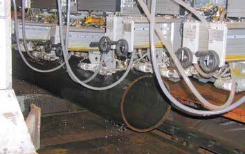
Fig 5: Typical External 5 wire weld / SAW Welding Machine, and typical digital
condition monitoring output Fig 6: SAWL pipe undergoing automated UT
Tack Welding
ID Welding
OD Welding
Rigorous testing of pipe integrity diameter were larger and permitted access. This performance was
Pipe manufacture commenced on 14th March 2014. The pipe attributed to the high degree of expertise and small diameter/thick
was produced by the UOE method (see Fig 4), at Tata Steel’s wall experience that Tata Steel has within its welding/operations
Hartlepool 42” UOE Mill. department, and the deployment of the digital control and weld
condition monitoring.
The pipes were welded using the SAWL process (see Fig 5); this takes
place after the O forming stage, but before the expansion process. For The final part of the manufacture involved removal of test pieces for
this project, a suitable 4/5 wire weld procedure specification (WPS) was batch release mechanical testing, followed by visual inspection, end
developed and a Titanium-Boron type welding wire/semi basic fully face bevelling, dimensional confirmation, peripheral non-destructive
agglomerated flux combination was used. Welding control was assisted testing of pipe ends and stencilling/hard stamping with the pipe’s
by various new technologies that have recently been invested in within unique identity for the final traceability guarantee. This identity was
the 42” UOE Mill such as weld condition monitoring and digital front assigned to the pipe when it was in plate form at the start of the
end control of the SAWL welding process (see Fig 5). process of manufacture.
The welds were checked prior to expansion for defects using The dimensional confirmation was very important on this project; due
NDT techniques involving radiography and ultrasonics (UT). Once the to the intended installation method (reeling), there was a requirement
pipes were expanded, they were all hydrostatically tested to a to provide detailed information on the dimensional control at the pipe
minimum test pressure of 447 Bar for 10 seconds. After this, the pipes ends. Specifically, this focused on size and shape control. Tata Steel
received their final qualitative NDT check, via a 28 probe automated UT utilised its recently commissioned laser end profiler (see Fig 7) to
system (see Fig 6). Repair rates of < 0.5% were experienced; although generate detailed data files for each pipe end on all pipes.
no internal repairs were permitted due to the small diameter, the repair
rate quoted includes those pipes which could have been repaired if the
03Manufacture of Small Diameter/Thick Wall
Reelable DSAWL Linepipe
How Tata Steel develop product range for customers
Extensive experience Fig 7: Laser end profiler and typical output screen.
For the intended project, the critical dimensional performance items
were achieved and confirmed by the laser profiler; actual diametric
control based on 16 equally spaced axes was shown to be within
±2mm of nominal, and the out of roundness (OoR) at the pipe ends
were shown to meet 3mm maximum. Any pipes with OoR > 3mm had
the ends cut-back and were re measured for compliance. The control
on these dimensional parameters is essential to allow for the high level
of fit up required within the girth welds when installation by reeling
is being considered. Fig 8 shows the results obtained for size and
shape control.
Additionally, local out of roundness at the longitudinal weld area
(peaking) and wall thickness were evaluated; these are also critical
to controlling the final fit up of pipes during spool base operations.
Fig 9 below shows the excellent control achieved.
In terms of the manufacturing process conclusion, it was apparent
that excellent dimensional control and weld quality was delivered.
However, this performance was only possible due to the extensive
experience and development carried out by Tata Steel into the
particular requirements for successful manufacture of small
diameter and thick wall UOE line pipe.
Overcoming challenges in manufacturing small The deflection of the pipe is expressed in the equation:
diameter / thick wall line pipe
d = (Wx3)
The manufacture of small diameter thick wall pipe presents different
3EI
challenges than the manufacture of pipe with larger diameters.
This is manifested in two principle ways: Where W is the load, x is the length of the pipe, E is the modulus of
elasticity and I is the moment of inertia. The moment of inertia is the
• Pipe bending during welding crucial component (assuming all other factors are unchanged), and is
• Pipe expansion expressed as:
l = ∏ (OD4 - ID4)
During and just after the welding process, the weld contracts as it
64
cools; this has the effect of pulling the pipe into a bend (see Fig 10). To
combat this, the welding procedures and the equipment used must be This then shows that the deflection is greater at smaller diameters, and
able to deal with the associated effects of this bending. Specific that the diameter has a much greater effect than the wall thicknesses
measures represent particular Tata Steel intellectual property, but the typical for line pipe.
concepts of welding, head clearance and specific welding parameters
are key to achieving a satisfactory process. In addition to welding In summary, pipe manufacturers will see a dramatically different
concerns, the bend in the unexpanded pipe requires careful reaction when processing small diameter pipe; adequate measures
consideration of the pipe conveying throughout the mill, and the need to be in place to deal with this phenomenon, and these have
eventual clearances associated with the mechanical expander itself. been built up by Tata Steel through more than 20 years experience in
the manufacture of small diameter and thick wall pipes.
04Fig 8: Dimensional control at pipe ends: diametric size control and OoR.
406.4 x 22.2mm L450M Pipe End Inside Diameter - Diametrically 406.4 x 22.2mm L450M Pipe End Out of Roundness
1000 160
140
800
120
600 100
Frequency
Frequency
80
400
60
40
200
20
0 0
360.0
360.5
361.0
361.5
362.0
362.5
363.0
363.5
364.0
364.5
365.0
0.5
1.0
1.5
2.0
2.5
3.0
3.5
Inside Diameter (mm) OOR (mm)
16 measurements per pipe end from 942 pipes Mean 1.378
Mean 362.9 StDev 0.5177
StDev 0.5925 N 1884
N 30144
Fig 9: Peaking and wall thickness control at pipe ends.
406.4 x 22.2mm L450M Pipe End Inside Diameter Peaking 406.4 x 22.2mm L450M Pipe End Wall Thickness - Automatic
500 600
500
400
400
Frequency
Frequency
300
300
200
200
100
100
0 0
21.50
21.75
22.00
22.25
22.50
22.75
23.00
0.0
0.3
0.6
0.9
1.2
1.5
1.8
3.5
Peaking (mm) Wall Thickness (mm)
2 measurements per pipe end 3 measurements per pipe end
Mean 0.2315 Mean 22.16
StDev 0.2040 StDev 0.2090
N 3768 N 5652
Fig 10: Pipe bending on small diameter/thick wall pipe. Figure 11: Beam deflection example
Fig 10a: Pre welding - side view with weld at top End view
with weld
at top
Fig 10b: Post welding - side view with weld at top W
d
X
05Manufacture of Small Diameter/Thick Wall
Reelable DSAWL Linepipe
How Tata Steel develop product range for customers
The second specific challenge when manufacturing small diameter Figures 13 to 16 show the various stages in FE modelling before the
thick wall pipe by the UOE method involves the expansion of the pipe. expander that were developed. These allow Tata Steel to understand
The pressures associated with expansion of small diameter/thick wall the optimum die shape/profile, machine settings and incoming plate
pipe are high due to the hoop stress associated with their geometry. strength control necessary for as round a pipe as possible, with limited
This is analogous to the hydrostatic testing principle, where the shoulder flats.
formula for required hoop stress is expressed as
Figure 14 represents the typical output of the FE model and allows Tata
p= 2St
Steel to determine the correct crimp die profile to deliver the optimal
D
crimp shape. This is particularly important, as the rest of the forming
Where P = pressure, S = yield strength, t = wall thickness and process is mostly unable to influence this area of the pipe, so mitigation
D = diameter. As can be seen, reduction in diameter (smaller against peaking (local shape irregularity around the weld area) is
denominator) and increase in wall thickness (higher numerator) leads dependent on having a well modelled and powerful crimp press.
to a higher pressure and subsequent higher loads on the mechanical
expansion machine. It is the high loads associated with small diameters
Figure 12: shoulder flats on a UOE formed pipe
and thick walls that present the challenge; the load levels experienced
can be close to the machine limits, and so all the available load capacity
Weld
needs to be focused on expansion of the pipe and not on the
correction of any shape irregularities. Using a mechanical expander to Shoulder Shoulder
correct excessive shape irregularities (such as shoulder flats – see Fig
12) increases the loads experienced by the expansion head and the
D min (1)
associated pull rod. With the expansion load already near capacity
due to the diameter and wall thickness, this extra load can exceed
the machine capacity leading to machine failure and the loss of any
manufacturing capability. It should be noted that this phenomenon is D min (2)
likely to be more prevalent in JCOE manufacture, where the shoulder
flats can be experienced around the pipe circumference.
D max
Full forming process Out of roundness
The danger presented by this phenomenon means that manufacturers = Dmax D min
of small diameter and thick wall pipe should consider the whole
forming process and its ability to present as round a pipe as possible
to the expander. This alleviates the expander from correcting shape
before expanding the pipe properly and manages the load
experienced. In order to deliver as round a shape of pipe as possible to
the expander, Tata Steel invested heavily in reviewing the full forming
process; this included tooling design and a fully validated FE model.
Both of these features were fully integrated into each other, along with
the ability to determine the effect of different machine settings on the
final pre expansion shape.
06Figure 13: 2D modelling of the crimping process
C-press die open
C-press die open
Figure 14: 3D modelling of the crimping process
a
Positioning 1st bite (full, 900mm)
a a
b b
c
2nd bite (100mm overlap) 3rd bite (100mm overlap)
07Manufacture of Small Diameter/Thick Wall
Reelable DSAWL Linepipe
How Tata Steel develop product range for customers
Figure 15 below now shows typical outputs of the rest of the FE mean a loss of capability. The solution was to develop a die design
modelling process; by varying the input plate strength, machine which utilised a surface hardening heat treatment applied to a tougher
settings and die geometries, various outputs can be generated base tool steel grade. This permitted hard working surfaces to resist
(as shown in Figure 15 C) to show the degree of shape irregularities. wear, and a tough internal core to address the additional shock
In this way, the optimal settings and die configuration can be loading. In actual fact, the stated maximum thickness capacity of
chosen across the typical plate strength range being supplied. the 42” UOE Mill at 406.4mm OD L450MO is 21.0mm; the FE model and
associated tooling enhancements allowed the capacity to not only
An additional benefit of the FE modelling process is the ability to be increased to the design wall thickness of 22.2mm, but has defined
determine maximum capability of the various machines involved in a capacity maximum of up to 31.8mm for the same diameter and
forming the pipe. Tata Steel is now able to determine pressing capacity grade. Developing this capability is the declared strategy for
for the crimp press, the U Press and the O Press without the need for Tata Steel’s 42” UOE Mill.
expensive trials. This ability has been reapplied to the expander (see
Fig 16), where the FE model has allowed Tata Steel to determine that In summary, the successful forming of small diameter and thick wall
the previous limits in terms of wall thickness could be revised upwards. line pipe requires full understanding of the forming process involved,
with added requirement that each of the steps feeds into the next
Finding solutions so that a fully integrated model is obtained. However, an as yet
Accessing the additional capacity was made possible by developing unmentioned requirement is experience; the specific fitting together
the expander tooling to be able to withstand the increased pressures. of all of these requirements (including how to deal with the pipe
This meant considering the balance of properties that would be bending phenomenon detailed earlier) cannot be achieved in
required at high pressures; too hard and cracking could occur, and too a single period, and must be developed over time.
soft and die wear would increase exponentially. Both outcomes would
Figure 15: Typical FE model output of U-press (A) and O-press (B), along with final FE predicted shape vs perfect roundness (C)
-0.00E+01
-3.00E-01 -2.00E-01 -100E-01 0.00E+00 1.00E-01 200E-01 300E-01
-100E-01
-200E-01
A -300E-01 C
-400E-01
B
-500E-01
-600E-01
Key
OD Shape: as formed
OD Shape: deviation from average radius X10
08Figure 16: Typical FE modelling output for the mechanical expander (A); typical expander die configuration (B)
1st bite 2nd bite
16A
3rd bite 4th bite
Die
Cone Section
16B
Key
Softer, ‘shock absorbent‘ core Harder, wear resistant outer surfaces
09Manufacture of Small Diameter/Thick Wall
Reelable DSAWL Linepipe
How Tata Steel develop product range for customers
Confirming the reelability of SAWL line pipe In order to strain specimens correctly, rectangular panels 95 mm wide x
During the supply of the 406.4mm x 22.2mm L450MO material, 700 mm in length were extracted by flame cutting from the test pipe.
there was a requirement to confirm the behaviour of the material Panels were removed from 3 locations around the circumference; the
after it had undergone a strain cycle similar to that which would weld (with weld in the centre of the width), 90° from the weld and 180°
be experienced when reeling on and off the lay barge (see typical from weld according to the normal test locations specified in DNV
examples in Figure 17). Due to project timescales, this was undertaken OS-F101. Strain gauges were applied to the samples in line with the
using small scale testing as opposed to full scale simulation. The recommendations of DNV OS-F101 Appendix B, B1108; the target strain
required tests were based on those associated with Supplementary would be deemed to have been reached when the average of the first
Requirement P from DNV OS-F101; Table 2 below provides a summary pair of strain gauges achieved the required strain level. The samples
of tests that were agreed to be conducted as part of the were then subjected to the strain cycles above which were defined by
manufacturing procedure qualification. the end client and the lay contractor. This work was carried out at Tata
Steel’s RD&T Centre in Rotherham using a 2000kN servo-hydraulic test
machine with hydraulic grips. Figure 18 shows the typical test piece
configuration and a typical pre and post strained sample.
Figure 17: Typical strain cycles for reeling that were applied to small scale samples; starting with 3% tensile strain and ending with 0.5% compressive strain
(left) and starting with 3% compressive strain and ending with 0.5% tensile strain (right)
35000 15000
30000 10000
25000 5000
0
Microstrain (uE)
20000
Microstrain, uE
-5000 0 100 200 300 400 500 600 700 800
15000
-10000
10000
-15000
5000
-20000
0 -25000
0 100 200 300 400 500 600
-5000 -30000
-10000 -35000
Time 1 (seconds) Time s
Key Key
(TOP OS) ue (TOP IS) ue (BOTOS) ue (BOTIS) ue (CLOS) ue (CLIS) ue (TOP OS) ue (TOP IS) ue (BOTOS) ue (BOTIS) ue (CLOS) ue (CLIS) ue
Table 2: Mechanical Test Requirement Summary for DNV OS-F101 Supplementary Requirement P
As welded long. tensile Strained and aged Strained and aged all Strained and aged Strained and aged base Stained and aged weld
long. tensile weld tensile hardness material Cv metal Cv
• SMYS • SMYS • SMYS • 2 70Hv10 base and weld • As per Table 7-5 (same as • 45J Ave
• SMTS •SMTS •SMTS • 300Hv10HAZ unaged), depending on • 38J ind
Supp Req F
• Elongation as per Table 5-7 • %15 min elongation • %15 min elongation • Tested at same
• YS range = 100MPa max temperature as
unaged Cv
• Y/T = 0.90 max (recommended)
Fig 18: Small scale supplementary P typical test piece configuration and pre/post examples
130mm
95mm
50mm 50mm
Strain Gauges
700mm
10This approach allowed faster mobilisation to complete the required These results were considered to adequately confirm the pipe’s ability
tests, but was quite challenging to avoid buckling of the test pieces to be reeled. It should be pointed out that this outcome was not
during the compression stages. An additional concern was the limited necessarily a surprise or really ever in doubt; Tata Steel had supplied
amount of material available within each test piece to extract actual several hundred kilometres of 457mm OD Grade L415MO pipe in
test pieces from. However, this difficulty was planned for, and the thicknesses ranging from 22.2mm to 28.6mm to two reeled contracts
required number of test pieces were generated with the correct strain in the Gulf of Mexico in the early 2000’s. The difference now is that
cycles and were successfully tested. the proving procedure for reelability has become more detailed in
the last few years than was the case in the early 2000’s; although the
As expected, the requirements of Supplementary Requirement P requirements are very similar (as the reeling process hasn’t changed
of DNV OS-F101 were met, with the strain cycle ending in tension significantly in terms of strain cycles), a greater degree of confidence
giving the most significant increase in strength properties (again, is required.
as expected). The ‘as manufactured’ longitudinal tensile strength
met the requirement of 100MPa range for minimum to maximum
recorded Rt0.5, and the longitudinal Y/T ratio met the recommended
0.90 maximum. Table 3 below summarises the test results achieved.
Table 3: Summary of mechanical test results required to confirm achievement of DNV OS-F101 Supp. Req. P
Condition Parameter No of Results Min Max Mean DNV OS-F101 Supp. Req. P
Achieved?
As Manufactured Long. Body Rt0.5 (MPa) 64 460 524 489 Yes
Long. Body Rm (MPa) 64 547 584 565 Yes
Long. Body Y/T 64 0.83 0.90 0.86 Yes
Long. Body %El 64 24 28.5 26 Yes
Rt0.5 range (100MPa) 64 N/A Yes
Strain Condition 1 (start with Long. Body Rt0.5 (MPa) 6 459 494 476 Yes
%3 tensile strain and finish with Long. Body Rm (MPa) 6 561 588 574 Yes
%0.5 compressive strain) Long. Body %El 6 26 31 28 Yes
All Weld Rt0.5 (MPa) 3 633 651 644 Yes
All Weld Rm (MPa) 3 718 726 722 Yes
All Weld %El 3 20 25 22 Yes
Body Hv10 18 187 212 204 Yes
HAZ Hv10 54 188 237 208 Yes
Weld Hv10 27 225 254 245 Yes
Body CvN Ind (J) 9 246 428 400 Yes
Weld CvN Ind (J) 9 127 159 142 Yes
Strain Condition 2 (start with Long. Body Rt0.5 (MPa) 6 558 574 567 Yes
%3 compressive strain and Long. Body Rm (MPa) 6 573 594 584 Yes
finish with %0.5 tensile strain) Long. Body %El 6 24 26 25.5 Yes
All Weld Rt0.5 (MPa) 3 713 747 732 Yes
All Weld Rm (MPa) 3 715 737 729 Yes
All Weld %El 3 18 21 20 Yes
Body Hv10 18 187 215 204 Yes
HAZ Hv10 54 187 225 207 Yes
Weld Hv10 27 225 251 243 Yes
Body CvN Ind (J) 9 304 430 402 Yes
Weld CvN Ind (J) 9 128 156 142 Yes
11Tata Steel will be continuing to develop its understanding of the
Conclusion
reaction to reeling of its small diameter/thick wall SAWL pipe, and is
In summary, Tata Steel has deployed a combination of experience and
planning to conduct full scale simulations over the next few years.
newly developed technology to both increase the maximum thickness
Additionally, through the use of the validated FE model, the maximum
of pipe that can be produced for a 406.4mm OD grade L450MO pipe,
wall thicknesses that Tata Steel can now reliably manufacture in the
and to reconfirm the reelability of SAWL pipe. While reeling of SAWL
Subsea, Umbilical, Riser and Flowline (SURF) size ranges has
line pipe has been successfully undertaken in the past, it has been
increased, and is captured in Table 4, below.
several years since these initial steps into the reeling arena were taken.
Additionally, the codes controlling reel installation (specifically DNV
This capability is the culmination of a number of key technologies
OS-F101) and many offshore installation and operators specifications
deployed by Tata Steel over the last 20 years; tooling excellence, FE
have been enhanced as the understanding of what is required and
modelling excellence, continuous improvement excellence, welding
what happens during reeling has grown.
excellence and characterisation excellence. The result is an SAWL
capability able to support the market trends looking at increased
capabilities in the small diameter and thick wall size ranges.
Table 4: Revised SURF size range for Tata Steel 42” Mill
Size Capability Diameter (mm)
X65/L450 406.4 457.2 508 558.8
19.1 3 3 3 3
20.6 3 3 3 3
22.2 3 3 3 3
Wall Thicknesses (mm) 23.8 3 3 3 3
25.4 3 3 3 3
28.6 Being developed 3 3 3
31.8 Being developed 3 3 3
35 3 3 3
38.1 3* 3*
* These sizes may require discussion on length range.
Author
Martin Connelly, Technical Manager, Tata Steel
Co-authors
Graham Alderton, Manager – Technical Services (SAW Mills), Tata Steel
Stephen Hall, Manager – Technical Support & Development (SAW Mills), Tata Steel
Andrew Hill, Works Manager – SAW Mills, Tata Steel
Adam Bannister, Scientific Fellow, Tata Steel, RD&T
Shuwen Wen, Principal Scientist, Tata Steel, RD&T
Kamal Rajput, Sales Manager, Tata Steel, Energy & Power
Barry Rust, Product Marketing Manager, Tata Steel, Energy & Power
www.tatasteeleurope.com
Tata Steel
PO Box 101, Weldon Road, Corby, While care has been taken to ensure that the information contained in this
brochure is accurate, neither Tata Steel Europe Limited nor its subsidiaries accept
Northants NN17 5UA, United Kingdom responsibility or liability for errors or information which is found to be misleading.
T: +44 (0)1536 402121 F: +44 (0)1536 404111 Tata Steel Europe Limited is registered under number 05957565 with registered
energyprojects@tatasteel.com www.tatasteelenergy.com office at 30 Millbank, London, SW1P 4WY.
Copyright 2015
English Language EP30-v1:30:PDF:UK:03/15 Tata Steel Europe LimitedYou can also read