Design and Workspace Characterisation of Malleable Robots
←
→
Page content transcription
If your browser does not render page correctly, please read the page content below
Design and Workspace Characterisation of Malleable Robots
                                                                Angus B. Clark, Student Member, IEEE and Nicolas Rojas, Member, IEEE

                                            Abstract— For the majority of tasks performed by traditional
                                         serial robot arms, such as bin picking or pick and place, only
                                         two or three degrees of freedom (DOF) are required for motion;
                                         however, by augmenting the number of degrees of freedom,
arXiv:2009.06458v1 [cs.RO] 14 Sep 2020

                                         further dexterity of robot arms for multiple tasks can be
                                         achieved. Instead of increasing the number of joints of a robot
                                         to improve flexibility and adaptation, which increases control
                                         complexity, weight, and cost of the overall system, malleable
                                         robots utilise a variable stiffness link between joints allowing the
                                         relative positioning of the revolute pairs at each end of the link
                                         to vary, thus enabling a low DOF serial robot to adapt across
                                         tasks by varying its workspace. In this paper, we present the
                                         design and prototyping of a 2-DOF malleable robot, calculate
                                         the general equation of its workspace using a parameterisation
                                         based on distance geometry—suitable for robot arms of variable
                                         topology, and characterise the workspace categories that the
                                         end effector of the robot can trace via reconfiguration. Through
                                         the design and construction of the malleable robot we explore
                                         design considerations, and demonstrate the viability of the
                                         overall concept. By using motion tracking on the physical robot,       Fig. 1.    The developed two-degree-of-freedom (DOF) malleable robot
                                         we show examples of the infinite number of workspaces that             arm, showing various topology configurations it can achieve. A PUMA-like
                                                                                                                configuration is shown in foreground.
                                         the introduced 2-DOF malleable robot can achieve.
                                                               I. I NTRODUCTION
                                            When considering the design of any robot manipulator,               of proposed research regarding reconfigurable mechanisms
                                         the first and foremost design consideration is the number of           has focused on the design of modular robot arms, that
                                         degrees of freedom (DOF) the robot will have. To determine             are capable of providing system flexibility [13], [14], [15].
                                         the DOF, typically the tasks for the robot are considered,             However, these designs are still limited by the complexity
                                         determining the requirements of the design [1]. For the                of their control and motion planning. Development of serial
                                         majority of tasks performed by serial robots, only a low               robot arms that are capable of achieving this flexibility while
                                         DOF is required [2]. However, determining this, and thus the           maintaining low complexity has been limited. We propose
                                         required parameters of the robot, can be difficult to predict          to solve this problem using malleable robots, which can
                                         [3]. Serial robot arms are therefore either designed to be             be also catalogued as reconfigurable robot arms. Malleable
                                         hyper-redundant with more DOF than required, and therefore             Robots are defined as reduced-DOF serial arms of change-
                                         expensive, or are designed with the exact DOF required,                able geometry [16], whereby the integration of a variable
                                         which can limit their scope of application [4].                        stiffness continuously bending link between joints allows the
                                            Soft robotic manipulators have provided one solution to             relative positioning of revolute pairs to vary, producing a
                                         the issue of requiring high DOF for achieving high dexterity,          variable robot topology, while the reduced DOF maintains
                                         with the development of continuously bending manipulators              the simplicity of the system.
                                         (continuum robots) [5], [6]. The natural conformity and                   The inherent non-fixed robot geometry of malleable robots
                                         bending of soft manipulators allows for a high adaptability            allows the generation of an infinite number of workspaces
                                         across tasks [7]. However, accurate motion planning and                for adapting the system to different tasks. The workspace
                                         control, as well as high structural strength, have proved              of a robot arm is defined as the region (or surface/volume)
                                         difficult to achieve [8]. Variable stiffness technologies have         within which every point can be reached by the end effector,
                                         recently been implemented in these robots to improve their             and is one of the most important specifications for both
                                         strength while maintaining their flexibility [9], [10], [11].          robot designers and users [17]. We can either compute the
                                            The design of robot mechanisms that are capable of chang-           workspace given the structure (analysis), or alternatively
                                         ing the mode of motion or the number of DOF of the robot               determine the robot structure from a desired workspace
                                         have been called reconfigurable [12]. The significant majority         (synthesis) [18]. For the case of malleable robots, traditional
                                                                                                                strategies for the computation of workspaces based on the
                                           Angus B. Clark and Nicolas Rojas are with the REDS Lab,              attachment of reference frames to the robot joints, such as
                                         Dyson School of Design Engineering, Imperial College London,
                                         25 Exhibition Road, London, SW7 2DB, UK (a.clark17,                    those that make use of the Denavit-Hartenberg convention
                                         n.rojas)@imperial.ac.uk                                                [19], [20], cannot be employed since both link dimensions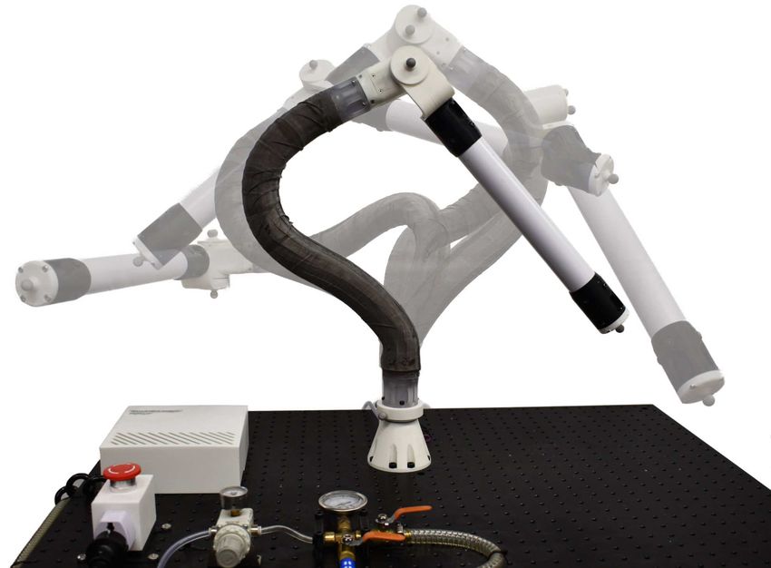
and the relative orientation of the joints can change. An
alternative is to perform the workspace analysis using screw
theory [21], [22] or distance geometry [23] as in these
approaches the parameterisation does not depend on relative
angles and distances between joint reference frames. We
make use of a distance-geometry-based method herein as the
technique has been shown to simplify the computation of the
workspace equation of complex mechanisms [24], [25].
We introduce a first-of-its-kind malleable robot, as shown
in Fig. 1, consisting of two rotary joints, a malleable link of
variable stiffness with structural spine designed for collab-
orative extrinsic reconfiguration [16], [26], and a rigid link
connecting the second joint to the end effector. By lowering
the stiffness of the malleable link via vacuum elimination,
this can be reshaped by hand as desired. Then, by stiffening
the link again using negative pressure, the joints are fixed
in place, forming a new robot topology. To the best of the
authors’ knowledge, no workspace calculation or analysis
has yet been performed for malleable robots, and this work
is the first demonstration of the viability and capabilities of Fig. 2. For workspace characterisation, a 2-DOF malleable robot arm
can be modelled as the bar-and-joint framework formed by connecting with
this technology, presenting physical examples of the infinite edges 5 points: P1 and P2 , which define the first axis; P3 and P4 , which
number of workspaces that a 2-DOF malleable robot can define the second axis; and P5 , which corresponds to the centre of the end
achieve. effector.
The rest of this paper is organised as follows. Firstly,
in section II, the distance-based parameters and main set Cayley-Menger determinant of these is defined as [23]
of formulae defining the malleable robot workspace are
0 1 1 1 1 1
identified, and then the symbolic equation of the workspace 1 0 s1,2 s1,3 s1,4 s1,5
surface traced by the end effector of a 2-DOF malleable 1 1 s1,2 0 s2,3 s2,4 s2,5
robot is obtained, along with a presentation of its workspace D(1, 2, 3, 4, 5) = − ,
16 1 s1,3 s2,3 0 s3,4 s3,5
categories. In section III, we discuss the design of the 1 s1,4 s2,4 s3,4 0 s4,5
malleable robot, with considerations of specific aspects of 1 s1,5 s2,5 s3,5 s4,5 0
this, such as the malleable link and joints. In section IV and where si,j = d2i,j = ||pi − pj ||2 is the squared distance
V, we present and comment on the workspaces generated between Pi and Pj , and pi is the position vector of point Pi
by the malleable robot prototype. Finally, we conclude in in the global reference frame. For the general point sequence
section VI. P1 , P2 ,. . .,Pn , the Cayley-Menger determinant gives (n −
1)!2 times the squared hypervolume of the simplex spanned
by the points in En−1 [27]. Hence, D(1, 2, 3, 4, 5) = 0 in E3 .
II. W ORKSPACE D EFINITION Since D(1, 2, 3, 4, 5) = D(4, 3, 2, 1, 5) = 0, using properties
of the determinant of block matrices [28], it can be shown
We define our 2-DOF malleable robot with a vertical that this condition can be compactly expressed using 3 × 3
rotary joint at the base, connected co-linearly to one end of matrices as
a malleable link, which terminates at a second rotary joint D(1, 2, 3, 4, 5) = 2 s1,2 s1,5 s2,5 det(A − BCBT ) = 0,
mounted perpendicularly to the other end of the malleable (1)
link. A second, rigid link is then attached to the second rotary
joint, also perpendicularly, which then terminates at the end where
effector. Since a link connecting two skew revolute axes can 0 1 1 1 1 1
be modelled as a tetrahedron by taking two points on each A= 1 0 s3,4 , B = s2,4 s1,4 s4,5 , and
of these axes and connecting them all with edges, and a 1 s3,4 0 s2,3 s1,3 s3,5
s1,5 1 1
rigid link connected to a revolute axis can be modelled as − s1,2 s2,5 s1,2 s2,5
a triangle by taking two points on the axis and a point at 1 1 s 1
C= s1,2 − s1,22,5
s1,5 s1,5 .
the end of the link and connecting them all with edges [24], 2 1 1 s
s2,5 s1,5 − s1,5 s2,5
1,2
then we can model a 2-DOF malleable robot as the bar-and-
joint framework involving 5 vertices (points) and 10 edges Following the notation of Fig. 2, equation (1) is solely
shown in Fig. 2, where P5 corresponds to the centre of the satisfied in the points in E3 where a 2-DOF malleable robot
end effector. can physically exist. This fact can be exploited to compute
Given a sequence of five points P1 , P2 , P3 , P4 , P5 , the the Cartesian equation of the robot workspace, say Γ(x, y, z),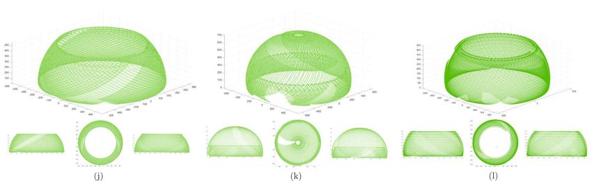
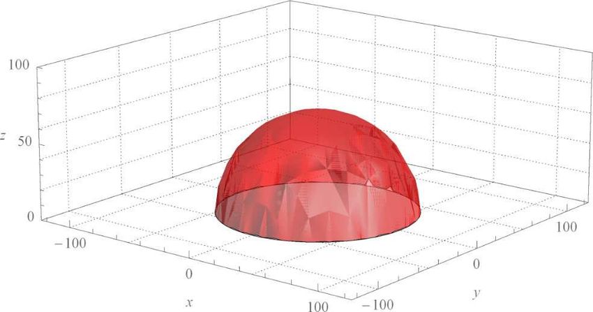
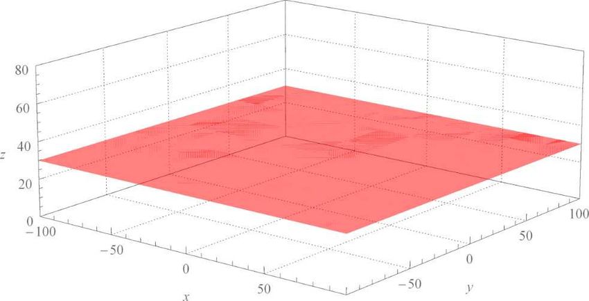
Fig. 3. Simulated example workspaces for each type of robot topology achievable by a 2-DOF malleable robot: (a) General Articulated, (b) PUMA-like,
(c) SCARA, and (d) Spherical.

by deriving the locus of point P5 , the end effector, whose                B. PUMA-like (or variable centre and radius) case
coordinates are p5 = (x, y, z) in a particular reference frame.               In a PUMA-like robot configuration, the two revolute axes
To simplify this computation we can assume, without loss of                of the robot are perpendicular and coincide at a point located
generality, that P1 equals the origin of the global reference              in the positive side of the z-axis, such that points P2 and P4
frame and that P2 is located in the positive side of the z-axis,           are coincident, and the angle ∠P1 P2 P3 is π2 . Thus, s2,4 = 0,
such that p1 = (0, 0, 0) and p2 = (0, 0, d1,2 ). Therefore,                s1,4 = s1,2 , s3,4 = s2,3 , and s1,3 = s1,2 + s2,3 . Substituting
                                                                           these values into (3), we get
             s1,5 = x2 + y 2 + z 2
                                                                    (2)                         def
             s2,5 = x2 + y 2 + z 2 − 2d1,2 z + s1,2 .                             ΓB (x, y, z) = x2 + y 2 + (z − d1,2 )2 − s4,5 = 0,           (5)
                                                                           which corresponds to the equation of a sphere of radius
  Substituting equation (2) into equation (1), fully expanding
                                                                           d4,5 centred at P2 . Observe that in this case the centre
the result and rearranging terms, we get
                                                                           (0, 0, d1,2 ) and radius d4,5 are not constant, they can be
             def                                                           adjusted according to need. The same equation is obtained
 Γ(x, y, z) = q0 (x2 + y 2 + z 2 )2 + q1 d1,2 z (x2 + y 2 + z 2 )
                                                                           when the perpendicularity of the two axes is relaxed. An
            q2 x2 + q2 y 2 + q3 z 2 + q4 d1,2 z + q5 ,              (3)    example of such a workspace can be seen in Fig. 3(b).
where qi , i = 0, . . . , 5 are polynomials in s1,2 = d21,2 , s1,3 ,       C. SCARA (or planar) case
s1,4 , s2,3 , s2,4 , s3,4 , s3,5 , and s4,5 . Γ(x, y, z) is an algebraic      In a SCARA robot configuration, the two revolute axes of
surface of degree 4 (a quartic surface) that corresponds to the            the robot are parallel. Using projective geometry arguments,
workspace surface, traced by the end effector (point P5 ), of a            this implies that there exist a point in the second axis, say
2-DOF malleable robot. The expressions of the polynomials                  P3 , such that the distance between it and the xy-plane is δ,
qi cannot be included here due to space limitations; these                 with δ > 0, δ → ∞. Hence, d1,3 = δ, d2,3 = d1,2 + δ,
polynomials can be easily reproduced using a computer                      d3,4 = z4 + δ, d3,5 = z5 + δ, being zi the distance between
algebra system following the steps given above.                            Pi and the xy-plane. Substituting these values into (3),
   By providing constraints to the two revolute axes of the                we obtain an equation that can be written as a quadratic
malleable robot, we can define certain workspace categories                polynomial in δ, say Ω = k2 (x, y, z)δ 2 + k1 (x, y, z)δ +
belonging to specific robot configurations (topologies). Mal-              k0 (x, y, z) = 0. By factoring out δ 2 in this polynomial, we
leable robots are a general purpose serial robot, and so                   get Ω = δ 2 (k2 (x, y, z) + k1 (x,y,z)
                                                                                                            δ     + k0 (x,y,z)
                                                                                                                         δ     ) = 0. Since
follow similar applications where the task workspace defines               δ → ∞, then Ω = k2 (x, y, z) = 0.
the configuration. The robot configurations we define are                     Since the two revolute axes of the robot are parallel, we
spherical, PUMA-like, SCARA, and general articulated. The                  have to include additional constraints in Ω = k2 (x, y, z) = 0,
constraints for each of them are discussed next.                           that is, P2 =P4 =P ∞ . This implies that s2,4 = 0 and d1,4 =
                                                                           d1,2 . Substituting these values into Ω = k2 (x, y, z) = 0, we
A. Spherical (or variable radius) case                                     get (z4 − d1,2 ) s1,2 Φ(x, y, z) = Φ(x, y, z) = 0. We can then
                                                                           include the final constraint z4 = d1,2 (as P2 =P4 ) in the result
   In a spherical robot configuration, the two revolute axes
                                                                           (Φ(x, y, z)). This yields,
of the robot coincide at the base, such that, according to the
                                                                               (z − z5 ) x2 + y 2 + z 2 − 2 d1,2 z + d1,2 2 − s4,5 = 0.

notation of Fig. 2, points P1 and P3 are coincident. Thus,
s1,3 = 0, s2,3 = s1,2 , and s3,4 = s1,4 . Substituting these
values into (3), we obtain                                                 Following a similar procedure in the above equation to that
                                                                           done for δ, but in this case for d1,2 (d1,2 → ∞ since P2 =
                          def
            ΓA (x, y, z) = x2 + y 2 + z 2 − s3,5 = 0,               (4)    P4 = P ∞ ), we finally get
                                                                                                            def
                                                                                              ΓC (x, y, z) = (z − z5 ) = 0,                    (6)
which corresponds to the equation of a sphere of radius d3,5
centred at P1 . Observe that in this case the radius d3,5 is not           which corresponds to the equation of a plane parallel to
constant, it can be adjusted according to need. An example                 the xy-plane. Observe that z5 , the distance between the end
of this workspace can be seen in Fig. 3(d).                                effector and the xy-plane, is not constant and can be adjusted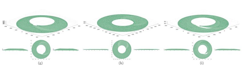
Fig. 4. Design of the developed variable stiffness malleable link showing
components and overall length/width ratio.

according to need. An example of this workspace can be seen                   Fig. 5.   Secondary rotary joint exploded CAD detailing components.
in Fig. 3(c).
D. General articulated
                                                                            a significant increase in rigidity, proportional to the nega-
  We define the general articulated robot configuration as                  tive pressure applied. The components of the implemented
any robot configuration that does not comply with any of                    malleable link can be seen in Fig. 4.
the constraints of the 3 other defined robot configurations,
thus the form of the workspace surface in this case is                      B. Joints and rigid link
Γ(x, y, z) = 0 (equation (3)). An example of this workspace,                   The primary joint, positioned at the base of the robot,
which corresponds to a torus, can be seen in Fig. 3(a).                     provides rotation in the z-axis. The secondary joint was
               III. M ALLEABLE ROBOT D ESIGN                                positioned at the end of the malleable link, providing rotation
                                                                            in the axis perpendicular to the termination end. Both joints
A. Malleable link                                                           were constructed from a Dynamixel MX-64 servo motor,
   To achieve the variable structure of the malleable link,                 with a 3D printed ABS housing, and a thrust ball bearing
variable stiffness technology was used, specifically layer                  (size 51106) providing force distribution of the motor torque
jamming with internal structural support [16], as this allowed              to the output side of the joint. The secondary joint com-
for both flexible shaping of the link, as well as rigid fixation            ponents can be seen in Fig. 5. The rigid link attached to
of a given configuration. Further, layer jamming has been                   the secondary joint has a length of 370 mm (actual distance
shown to give the highest jamming stiffness while utilising                 of 450 mm between joint axis and end effector). The link
a very small volume compared to other simple pneumatic                      was composed of a 42 mm  Polypropylene tube, and was
jamming solutions [26]. Due to the increased size of the                    attached to the robot using 3D printed ABS link ends similar
malleable link (50mm ) compared to typical variable                        to those used on the malleable link.
stiffness links designed for continuum surgery (∼15mm ),
other variable stiffness technologies capable of demonstrat-                               IV. P ERFORMANCE E VALUATION
ing higher stiffness, such as shape memory alloys (SMAs)                       To demonstrate the viability of the malleable robot concept
or low melting point alloys (LMPAs) were not considered                     and confirm its capability of generating an infinite number
due to the significant increase in transition time.                         of workspaces for different robot topologies, the workspace
   Layer jamming was achieved by flap pattern [29] laser cut                of the developed malleable robot was measured. Motion
Mylar sheet (0.18 mm), of 12 flaps spanning the circumfer-                  tracking markers were attached to each joint of the robot
ence of the link, with a minimum of 11 overlapping layers                   and the end effector. 7 OptiTrack Flex3 cameras were used
always in contact. The flap pattern was contained within two                to track the movement of the robot. The calibration report of
cylinder membranes of latex sheet (0.25 mm), and sealed                     the cameras detailed a mean 3D error for overall projection
with link termination ends 3D printed from Vero Clear on a                  as 0.455mm and overall wand error as 0.081mm. Before
Stratasys Objet 500, which also provided mounting points for                each experiment, the desired configuration of the robot was
an internal structural spine to prevent excessive deformation               selected. Using live tracking feedback from the motion
under extreme bending of the link, as well as mounting points               tracking cameras, the malleable robot was manually shaped
to attach the other components of the robot. The internal                   and fixed in position, with the pose measured by the tracking
spine [16] was 3D printed from Acrylonitrile Butadiene                      marker positions. 12 robot geometries were selected, 3 for
Styrene (ABS), with flexible couplings connecting the spinal                each of the workspace configurations defined in section II.
segments printed from Ninjaflex material. By changing the                      The geometric parameters of the robot (i.e., distances)
pressure inside the sealed latex membranes using a vacuum                   for each assessed configuration are presented in Fig. 6,
pump (BACOENG 220V/50Hz BA-1 Standard), the Mylar                           where the experiment results obtained are shown. Once each
layers compress together, and the cumulative friction causes                geometry was confirmed, the tracking markers on the joints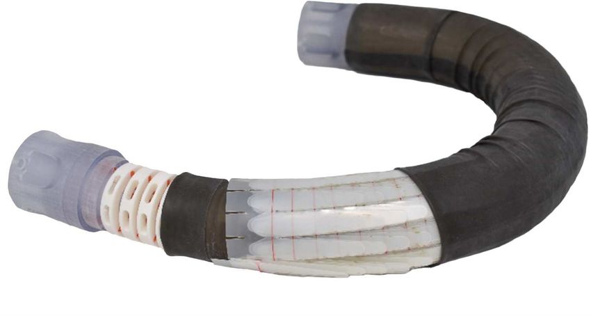
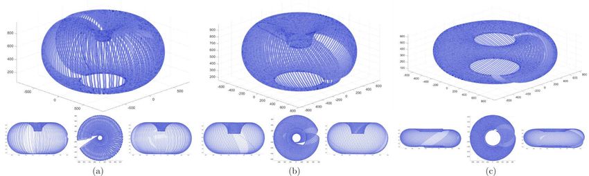
Fig. 6. Experimental results showing tracked overall workspaces of the 2-DOF malleable robot in 3 alternative configurations for each type of robot
topology, (Top: ISO, Bottom Left to Right: YZ, XY, and XZ): (a)(b)(c) General Articulated (dark blue), (d)(e)(f) PUMA-like (light blue), (g)(h)(i) SCARA
(dark green), and (j)(k)(l) Spherical (light green). Constant distances (in mm) across all configurations were d1,2 = 58, d3,4 = 49, d3,5 = 455, and d4,5
= 460. Specific distances (in mm) for each configuration were (a) d1,3 = 671, d1,4 = 670, d1,5 = 1009, d2,3 = 626, d2,4 = 625, d2,5 = 981, (b) d1,3 =
668, d1,4 = 656, d1,5 = 385, d2,3 = 620, d2,4 = 609, d2,5 = 3647, (c) d1,3 = 593, d1,4 = 618, d1,5 = 726, d2,3 = 558, d2,4 = 581, d2,5 = 718, (d)
d1,3 = 650, d1,4 = 667, d1,5 = 969, d2,3 = 603, d2,4 = 619, d2,5 = 930, (e) d1,3 = 523, d1,4 = 525, d1,5 = 529, d2,3 = 466, d2,4 = 469, d2,5 = 497,
(f) d1,3 = 642, d1,4 = 669, d1,5 = 551, d2,3 = 588, d2,4 = 614, d2,5 = 510, (g) d1,3 = 500, d1,4 = 544, d1,5 = 562, d2,3 = 451, d2,4 = 494, d2,5 =
520, (h) d1,3 = 569, d1,4 = 596, d1,5 = 503, d2,3 = 540, d2,4 = 564, d2,5 = 474, (i) d1,3 = 535, d1,4 = 581, d1,5 = 647, d2,3 = 483, d2,4 = 528, d2,5
= 604, (j) d1,3 = 395, d1,4 = 444, d1,5 = 614, d2,3 = 343, d2,4 = 392, d2,5 = 572, (k) d1,3 = 511, d1,4 = 559, d1,5 = 695, d2,3 = 472, d2,4 = 520,
d2,5 = 666, (l) d1,3 = 349, d1,4 = 396, d1,5 = 443, d2,3 = 299, d2,4 = 347, d2,5 = 441.
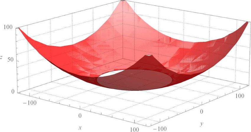
Fig. 7. Malleable robot topology configurations for each of the defined workspaces: (a) General Articulated, (b) PUMA-like, (c) SCARA, and (d)
Spherical.

were removed, leaving only the single marker on the end                  difficult to accurately achieve some of the intended con-
effector. The end effector was then moved throughout the                 figurations. As shown by Fig. 6(f), for instance, where a
entire workspace of each robot configuration by progressing              sphere was desired (PUMA-like case) but an overlapping
through all possible joint positions in steps of 0.088◦. Due             sphere, a form of a minimal torus, was obtained instead. This
to joint limits, the maximum angles actually achievable by               implies that the second revolute axis did not intersect the first
each joint were 10◦ to 350◦ and 53◦ to 307◦, for the primary             one as required—and then the robot geometry was that of
and secondary joint, respectively, with 0◦ aligned with the              the general articulated case. While the live feedback from
connecting link. Examples of each robot configuration can                the motion tracking markers allowed improved alignment
be seen in Fig. 7.                                                       of the joints over pure visual alignment, it did not account
                                                                         for the accuracy limitations of human manipulation. While
                         V. D ISCUSSION                                  the overall accuracy achieved was good for our purposes,
   The results (Fig. 6) show 4 distinct workspace configu-               as shown by the majority of the workspaces in the correct
rations related to the topologies general articulated, PUMA-             desired form, it is clear that a slight change in reconfigu-
like, SCARA, and spherical, with 3 different variations of               ration can be critical to the resulting workspace accuracy.
geometry within the same topology. For the general articu-               In fact, for industrial serial arms, accuracy is key, thus the
lated, PUMA-like, and spherical configurations, the physical             direction of malleable robots towards collaborative robots,
shape of the workspace demonstrated significant variation                where inaccuracies can easily be dynamically corrected, is
with the change of geometric parameters, producing flattened             key.
tori (general articulated case) [Fig. 6(c)] and variation in                                    VI. C ONCLUSIONS
the radius of the resulting sphere (PUMA-like and spherical
                                                                            In this paper we presented for the first time the de-
case) [Fig. 6(d)-(f) and Fig. 6(j)-(l)], respectively. For the
                                                                         velopment of a full malleable robot. It consists of two
SCARA case, only variations in workspace height (z-axis)
                                                                         revolute joints, a variable stiffness malleable link, and a
and internal radius were observed, due to the fixed length of
                                                                         rigid link connecting the secondary joint to the end effector.
the rigid link defining the width of planar surface. On each
                                                                         By increasing the pressure within the malleable link, the
of the resulting workspaces, we can observe a missing slice,
                                                                         link can be extrinsically (manually) reshaped, and fixed in
corresponding to areas not accessible by the motion tracking
                                                                         position by reducing the pressure, forming an alternative
cameras.
                                                                         configuration of the robot by varying the relative joint
   Considering the construction of the malleable robot, issues           orientations. The design of each malleable robot component
arise from the generated SCARA workspace. The SCARA                      was discussed, and using distance geometry, we derived
workspace should be a planar surface (equation (6)), with                the algebraic surface corresponding to the workspace of the
variation of the end effector only in the x and y direction.             robot. Through simulation, we demonstrated the 4 workspace
From the experimental results however, we observe a slight               categories achievable by a 2-DOF malleable robot (spherical,
variation in height across the workspace. As the robot under-            PUMA-like, SCARA, and general articulated). Using motion
goes movement, the centre of mass of the robot changes. Due              tracking cameras on the robot prototype, we demonstrated
to tolerances in the joints, specifically in the primary joint,          the variable workspace capability of a 2-DOF malleable
and wrinkles in the latex membrane, a slight variation in                robot, and confirmed the capacity of generating an infinite
height as the robot progresses through the joint positions can           number of workspaces, categorised into 4 surface area types.
be seen. While this variation is minimal it is an aspect that            While limitations were presented with the extrinsic reconfig-
must be considered in the production of malleable robots.                uration of the robot in accurately achieving some desired
To ensure minimal variation of the malleable link during                 workspaces, most of the intended geometries were correctly
an experiment, the joint speeds were reduced (25RPM),                    obtained. Future work may consider the implementation of
preventing extreme forces under directional changes.                     integrated motion sensors, or intrinsic control for achieving
   Finally, from the results we can identify that the man-               desired workspaces.
ual positioning of the robot (extrinsic reconfiguration) was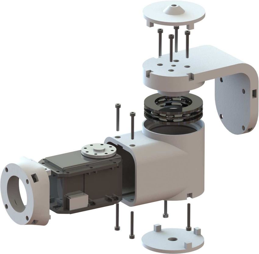
R EFERENCES                                       [15] Z. Bi and W.-J. Zhang, “Concurrent optimal design of modular robotic
                                                                                   configuration,” Journal of Robotic systems, vol. 18, no. 2, pp. 77–87,
 [1] H. Al-Dois, A. Jha, and R. Mishra, “Task-based design optimization of         2001.
     serial robot manipulators,” Engineering Optimization, vol. 45, no. 6,    [16] A. Clark and N. Rojas, “Stiffness-tuneable limb segment with flexible
     pp. 647–658, 2013.                                                            spine for malleable robots,” 2019 IEEE International Conference on
 [2] G. Yang and I.-M. Chen, “Task-based optimization of modular robot             Robotics and Automation (ICRA), 2019.
     configurations: minimized degree-of-freedom approach,” Mechanism         [17] Y. Tsai and A. Soni, “An algorithm for the workspace of a general
     and machine theory, vol. 35, no. 4, pp. 517–540, 2000.                        nr robot,” Journal of Mechanisms, Transmissions, and Automation in
 [3] O. Chocron and P. Bidaud, “Evolutionary algorithms in kinematic               Design, vol. 105, no. 1, pp. 52–57, 1983.
     design of robotic systems,” in Proceedings of the 1997 IEEE/RSJ          [18] K. Gupta and B. Roth, “Design considerations for manipulator
     International Conference on Intelligent Robot and Systems. Innovative         workspace,” Journal of Mechanical Design, vol. 104, no. 4, pp. 704–
     Robotics for Real-World Applications. IROS’97, vol. 2, 1997, pp.              711, 1982.
     1111–1117.                                                               [19] Y.-S. Kung and G.-S. Shu, “Development of a fpga-based motion
 [4] R. Cohen, M. Lipton, M. Dai, and B. Benhabib, “Conceptual design              control ic for robot arm,” in 2005 IEEE International Conference on
     of a modular robot,” Journal of Mechanical Design, vol. 114, no. 1,           Industrial Technology. IEEE, 2005, pp. 1397–1402.
     pp. 117–125, 1992.                                                       [20] Z. Li, R. Du, M. C. Lei, and S. M. Yuan, “Design and analysis of
 [5] I. D. Walker, “Continuous backbone continuum robot manipulators,”             a biomimetic wire-driven robot arm,” in ASME 2011 International
     ISRN robotics, vol. 2013, 2013.                                               Mechanical Engineering Congress and Exposition. American Society
 [6] A. D. Marchese, K. Komorowski, C. D. Onal, and D. Rus, “Design and            of Mechanical Engineers Digital Collection, 2011, pp. 191–198.
     control of a soft and continuously deformable 2d robotic manipulation    [21] G. Coppola, D. Zhang, and K. Liu, “A 6-dof reconfigurable hybrid par-
     system,” in 2014 IEEE International Conference on Robotics and                allel manipulator,” Robotics and Computer-Integrated Manufacturing,
     Automation (ICRA), 2014, pp. 2189–2196.                                       vol. 30, no. 2, pp. 99–106, 2014.
                                                                              [22] F. Xie and X.-J. Liu, “Design and development of a high-speed and
 [7] D. Rus and M. T. Tolley, “Design, fabrication and control of soft
                                                                                   high-rotation robot with four identical arms and a single platform,”
     robots,” Nature, vol. 521, no. 7553, p. 467, 2015.
                                                                                   Journal of Mechanisms and Robotics, vol. 7, no. 4, p. 041015, 2015.
 [8] F. Renda, M. Cianchetti, M. Giorelli, A. Arienti, and C. Laschi, “A
                                                                              [23] N. Rojas, “Distance-based formulations for the position analysis of
     3d steady-state model of a tendon-driven continuum soft manipulator
                                                                                   kinematic chains,” PhD dissertation, 2012.
     inspired by the octopus arm,” Bioinspiration & biomimetics, vol. 7,
                                                                              [24] N. Rojas and A. M. Dollar, “The coupler surface of the rsrs mecha-
     no. 2, p. 025006, 2012.
                                                                                   nism,” Journal of Mechanisms and Robotics, vol. 8, no. 1, p. 014505,
 [9] T. Ranzani, M. Cianchetti, G. Gerboni, I. De Falco, G. Petroni, and           2016.
     A. Menciassi, “A modular soft manipulator with variable stiffness,” in
                                                                              [25] N. Rojas, A. M. Dollar, and F. Thomas, “A unified position analysis of
     3rd joint workshop on new technologies for computer/robot assisted            the dixon and the generalized peaucellier linkages,” Mechanism and
     surgery, 2013, pp. 11–13.                                                     Machine Theory, vol. 94, pp. 28–40, 2015.
[10] S. Kim, C. Laschi, and B. Trimmer, “Soft robotics: a bioinspired         [26] A. B. Clark and N. Rojas, “Assessing the performance of variable
     evolution in robotics,” Trends in biotechnology, vol. 31, no. 5, pp.          stiffness continuum structures of large diameter,” IEEE Robotics and
     287–294, 2013.                                                                Automation Letters, vol. 4, no. 3, pp. 2455–2462, 2019.
[11] M. Cianchetti, T. Ranzani, G. Gerboni, T. Nanayakkara, K. Althoefer,     [27] K. Menger, “New foundation of euclidean geometry,” American Jour-
     P. Dasgupta, and A. Menciassi, “Soft robotics technologies to address         nal of Mathematics, vol. 53, no. 4, pp. 721–745, 1931.
     shortcomings in today’s minimally invasive surgery: the stiff-flop       [28] P. D. Powell, “Calculating determinants of block matrices,” arXiv
     approach,” Soft robotics, vol. 1, no. 2, pp. 122–131, 2014.                   preprint arXiv:1112.4379, 2011.
[12] P. C. Lopez-Custodio, J. M. Rico, J. J. Cervantes-Sánchez, and G. I.    [29] Y.-J. Kim, S. Cheng, S. Kim, and K. Iagnemma, “Design of a tubular
     Pérez-Soto, “Reconfigurable mechanisms from the intersection of              snake-like manipulator with stiffening capability by layer jamming,”
     surfaces,” Journal of Mechanisms and Robotics, vol. 8, no. 2, p.              in 2012 IEEE/RSJ International Conference on Intelligent Robots and
     021029, 2016.                                                                 Systems, 2012, pp. 4251–4256.
[13] O. Chocron, “Evolutionary design of modular robotic arms,” Robotica,
     vol. 26, no. 3, pp. 323–330, 2008.
[14] J. Baca, M. Ferre, and R. Aracil, “A heterogeneous modular robotic
     design for fast response to a diversity of tasks,” Robotics and Au-
     tonomous Systems, vol. 60, no. 4, pp. 522–531, 2012.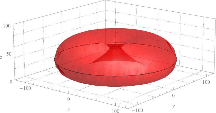
You can also read