Low-viewpoint forest depth dataset for sparse rover swarms
←
→
Page content transcription
If your browser does not render page correctly, please read the page content below

Low-viewpoint forest depth dataset for sparse rover swarms
                                                                            Chaoyue Niu, Danesh Tarapore and Klaus-Peter Zauner

                                            Abstract— Rapid progress in embedded computing hardware                 of a swarm of robots during exploration, the ability to accu-
                                         increasingly enables on-board image processing on small robots.            rately estimate terrain traversability is critical. By analyzing
                                         This development opens the path to replacing costly sensors                geometric features such as the depth map or point cloud,
                                         with sophisticated computer vision techniques. A case in point
                                         is the prediction of scene depth information from a monocular              and appearance characteristics such as colour or texture, a
                                         camera for autonomous navigation. Motivated by the aim                     terrain can be analysed with respect to the mechanical and
                                         to develop a robot swarm suitable for sensing, monitoring,                 locomotion constraints of a robot [2]. To support this analysis
arXiv:2003.04359v2 [cs.RO] 26 Oct 2020

                                         and search applications in forests, we have collected a set                for off-road path planning we are developing a vision system
                                         of RGB images and corresponding depth maps. Over 100000                    required to run on small, on-board computers. To also keep
                                         RGB/depth image pairs were recorded with a custom rig from
                                         the perspective of a small ground rover moving through a                   the cost of sensors low, we are interested in monocular depth
                                         forest. Taken under different weather and lighting conditions,             estimation [3] to predict local depth from single images or
                                         the images include scenes with grass, bushes, standing and fallen          sequences of images from a single moving camera. Aside
                                         trees, tree branches, leaves, and dirt. In addition GPS, IMU,              from optical flow [4] and geometric techniques [5], [6],
                                         and wheel encoder data were recorded. From the calibrated,                 machine learning has been applied to achieve this. A number
                                         synchronized, aligned and timestamped frames about 9700
                                         image-depth map pairs were selected for sharpness and variety.             of authors have trained depth estimation models by using
                                         We provide this dataset to the community to fill a need identified         deep neural network architectures ([7], [8], [9], [10], [11]).
                                         in our own research and hope it will accelerate progress                      Most existing outdoor depth map datasets focus on un-
                                         in robots navigating the challenging forest environment. This              manned driving applications. The KITTI dataset [12] records
                                         paper describes our custom hardware and methodology to                     street scenes in cities. The Freiburg Forest dataset [13]
                                         collect the data, subsequent processing and quality of the data,
                                         and how to access it.                                                      records the forest view from a cart track and lacks a
                                                                                                                    close-range perspective. Because this dataset was manually
                                                                 I. I NTRODUCTION                                   labeled for image segmentation it is comprised of only 366
                                                                                                                    images and therefore too small to train deep neural networks.
                                            Forests are ecologically and economically important, af-                The Make-3D dataset ([14], [15]) records outdoor scenes
                                         fecting the local as well as wider climate and are under                   including some with close-up depth data, but it mainly
                                         pressure from changing weather patterns and deceases. They                 concentrates on buildings in a city. We have found that
                                         are also a formidable challenge for small all-terrain ground               most of the publicly available RGB-D datasets are recorded
                                         robots. In ongoing research we are aiming at developing                    indoors [16]. While close-range depth data is available for
                                         a rover platform for this environment. We envisage robot                   these indoor conditions [17], this was so far not the case
                                         swarms as a useful tool in the efforts to protect, reform, and             for natural outdoor environments. Accordingly, the available
                                         extend forests.                                                            depth datasets were not suitable for our purpose. Moreover, a
                                            Robots swarms are teams of robots that coordinate their                 common feature of the above datasets is that the images are
                                         actions in a distributed fashion to perform an assigned task.              taken from a high point of view. Our interest is in small
                                         A common feature of existing swarms is the underlying                      portable robots that can be transported with a backpack.
                                         assumption that the robots act in close proximity to each                  The camera perspective of these robots will be from a low
                                         other [1]. For real-world, outdoor applications over extended              viewpoint and we therefore prefer a depth dataset with such
                                         areas, such a density is neither desirable nor feasible. A                 a low perspective.
                                         dense swarm would not only be very costly, but also highly
                                         intrusive to the environment. Recently available technologies                        II. M OBILE SENSOR PLATFORM SETUP
                                         in long range radio communication and efficient battery                       To facilitate efficient data collection we decided to man-
                                         technologies, however, allow for the reconceptualisation of                ually move the camera along the path to be recorded,
                                         swarms as scalable groups of robots acting jointly over                    rather than to record with a robot-mounted camera. The
                                         distances up to 1 km. Such robots need to be low cost and                  recording rig shown in Fig. 1 was constructed by attach-
                                         high in autonomy.                                                          ing two incremental photoelectric rotary encoders to an
                                            Safely navigating mobile robots in off-road environments                electrical enclosure box and mounting a 100 mm diameter
                                         such as in a forest, requires real-time and accurate terrain               wheel to each encoder. The encoders were connected to a
                                         traversability analysis. To enable safe autonomous operation               Micropython enabled ARM board (ItsyBitsy M4 Express,
                                                                                                                    Adafruit, NY, USA.) which made the time stamped rotary
                                           School of Electronics and Computer Science, University of Southampton,
                                         Southampton, U.K.                                                          encoder readings available over a USB connection. The
                                           Corresponding author: Chaoyue Niu cn1n18@soton.ac.uk                     enclosure was mounted at the end of a telescopic rod of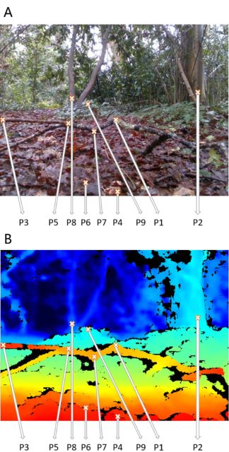
Fig. 1. Depth data collection rig. The recording system is equipped with
an Intel D435i global shutter depth camera, two rotary encoders, and a GPS.
A microcontroller monitors the incremental rotary encoders and interfaces
them to a USB connection.

                                                                              Fig. 3. Sample path for a data collection run. Trajectory (orange) from
                                                                              GPS meta data of data collection Run 1 (see Tab. 1) overlaid on aerial
                                                                              view to illustrate the recording environment in the Southampton Common.
                                                                              The white scale bar corresponds to a distance of 30 m. For all image
                                                                              frames of all runs the GPS metadata is included with the dataset. Google
                                                                              Maps background: Imagery©2020 Getmapping plc, Infoterra Ltd & Bluesky,
                                                                              Maxar Technologies; permitted use.

                                                                                                       TABLE I
Fig. 2. Sensor configuration. Top view of the mounting positions and            F OREST ENVIRONMENT RECORDING CONDITIONS . L UMINOSITY IN
dimensions of the sensors on the depth data collection rig. Solid black
                                                                                            ARBITRARY UNITS , SEE TEXT FOR DETAILS .
lines represent the wheels and the box; blue lines represent the sensors.
Dimensions in millimeter; the camera lens is located 150 mm above ground.

                                                                                                                          Number
                                                                                 Dataset    Weather                                    Mean
                                                                                                         Time of day      of images
                                                                                 index      condition                                  luminosity
the type used for paint rollers. This allows the user to roll                                                             recorded
the enclosure on its wheels along the ground by pushing                                     Partly
                                                                                 Run 1                   Midday           27,333       0.41
it forward while walking. Inside the enclosure a RealSense                                  sunny
D435i depth camera (Intel, CA, USA) was mounted 150 mm                                      Scattered
                                                                                 Run 2                   Midday           33,194       0.41
                                                                                            clouds
above ground with a free field of view in the direction of                                  Cloudy,
                                                                                 Run 3                   Evening          20,328       0.31
motion as illustrated in Fig. 2. The D435i camera combines                                  light rain
a depth camera and an RGB colour camera with a diagonal                          Run 4      Sunny        Afternoon        17,499       0.38
                                                                                            Mostly
field of view of 94◦ and 77◦ , respectively. With its global                     Run 5
                                                                                            clear
                                                                                                         Morning          36,331       0.37
shutter, this camera is well suited to a moving platform, and
it also contains an inertial measurement unit (IMU). A laptop
computer is connected to the camera, to the USB connection
from the rotary encoders and to a GPS receiver (BU-353-                       range from 0.0 to 1.0 in arbitrary units and give the average
S4 SiRF Star IV, US GlobalSat, FL, USA). The endurance                        over the luminosity of all frames (see next section) in the
of this rig is limited by the battery of the laptop used for                  run. Sample forest scenes from the runs are shown in Fig. 4.
recording and for monitoring the camera view while walking                    For each run in the forest the following data was recorded
with the rig.                                                                 from the sensor platform: (i) RGB and depth images from
                                                                              the camera, (ii) Linear acceleration and angular velocity from
             III. F OREST ENVIRONMENT DATASET                                 the six degree-of-freedom IMU of the camera, cf. Fig. 1 for
   The data for our forest environment dataset was collected                  axes orientation, (iii) rotary encoder counts, and (iv) GPS
in woodland areas (Fig. 3) of the 1.48 km2 Southampton                        position of the platform.
Common (Hampshire, UK).                                                          The data from the rotary encoder and IMU streams were
   The data collection rig was pushed through the forest area                 time synchronized with the recorded images from the camera
in the Southampton Common in five separate runs during                        at 30 frames per second, and recorded at the same rate. The
different times of day and different weather conditions to                    GPS location data was also synchronized with the camera
sample variations in lighting. Table I shows the recording                    feed, and recorded once per second. Recorded image data
conditions, where the luminosity values are normalised to                     was stored lossless in 8-bit PNG file-format at 640 × 480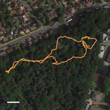
Fig. 4. Sample scenes from the forest environment dataset. A diverse set of scenes in RGB (left), and the aligned depth in grayscale (middle) and
color (right), were recorded in the forest. In grayscale, lighter pixels indicate regions further from the camera, and white pixels are out of range. The
gradients in depth are better illustrated in color, with warmer colored pixels indicating regions closer to the camera. In both color schemes, black pixels
indicate the depth could not be estimated.

pixel resolution. Data from the IMU, rotary encoder and GPS                    vision to calculate depth, but augments this technique by
sensors were stored for ease of access as comma-separated                      projecting with an infra-red laser a dot pattern into the scene.
values in a plain text file. Our full forest data-set comprises                This process should be reasonably robust against camera
over 134000 RGB/depth image pairs with concomitant meta-                       motion, but could potentially be susceptible to illumination
data. A convenient subset containing about 9700 aligned                        levels of the scene. For our analysis, the instantaneous
RGB and depth image pairs with the corresponding time                          velocity and acceleration of the mobile sensor platform was
synchronized IMU, rotary encoder, and GPS information is                       estimated using the rotatory encoders data. As a proxy for
available online DOI:10.5281/zenodo.3945526 un-                                actual illumination measurements we calculate a scalar lumi-
der Creative Commons Attribution 4.0 International Public                      nosity (perceived brightness) value from the color channels
License.                                                                       of the RGB pixels and averaged over all pixels in the image
                                                                               to arrive at the normalised luminosity of the frame (arbitrary
 IV. Q UALITY OF OUR FOREST ENVIRONMENT DATASET                                units).
   To assess the image quality of the depth data in our forest                    The recording rig was pushed at speeds comparable to
environment dataset we consider, (i) the fill rate, which is                   what we expect for portable robots in the forest environment
the percentage of the depth image containing pixels with a                     (Fig. 5). We found that over this speed range the fill rate is
valid estimated depth value, (ii) the depth accuracy using                     not affected by the velocity of the camera, as seen in Fig. 6A.
ground truth data, and (iii) the image perspective that can be                 Similarly, the fill rate is not affected by the luminosity of
determined by camera orientation.                                              the scene (Fig. 6B) and generally across the luminosity and
Fill rate of depth images: The depth camera uses stereo                        velocity range tested the camera achieves a reasonably high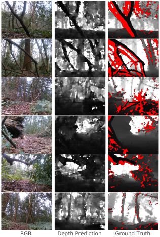
fill rate (mean 0.84 ± 0.11 SD across all depth images from
all five runs).
                             A                                         25
                                                                            B
                        25
 Percentage instances

                                                                       20
                        20

                                                                       15
                        15

                                                                       10
                        10

                        5                                              5

                        0                                              0
                             0.05 0.15 0.25 0.35 0.45 0.55 0.65 0.75        -1.75 -1.25 -0.75 -0.25 0.25 0.75 1.25 1.75
                                   Velocity (m/s)                               Acceleration (m/s 2)

Fig. 5. Velocity and acceleration during recording. The linear velocity
and acceleration of the mobile sensor platform in the forward direction,
while being pushed through the forest. Data for the distribution was
aggregated across all five runs of the dataset. Instantaneous velocity and
acceleration were estimated from the rotatory encoder data.

Accuracy of depth images: To evaluate the accuracy of the
depth images, we established ground truth depth measure-
ments with a Zamo Digital distance meter (Bosch, Germany;
maximum range 20 m, accuracy ±2 mm). For ground truth
measurements nine points at varying depths in a typical
forest scene were considered. The selected points, depicted
in Fig. 7, were located on the forest floor, on fallen leaves,
fallen tree branches, and low on tree trunks. Ground truth
measurements were replicated thrice for each of the nine
selected points. An offset of 4.2mm was added to values
returned by the ground truth sensor to account for differences
in its incident position and that of our depth camera. To                                                                    Fig. 7. Position of sampled points for accuracy of depth images. Nine
                                                                                                                             points at varying depth and positions were sampled from a typical forest
account for the divergence of the laser from the ground                                                                      scene. Points 1, 3, 5 and 7 are on a fallen tree brach, points 4 and 6 are
truth sensor, depth estimates with our depth camera were                                                                     part of the forest floor, particularly close to the camera, and points 2, 8 and
averaged over 7×7 pixels at the laser spot. Two independent                                                                  9 are located on tree trunks close to the ground. The points 4 and 8, are
                                                                                                                             nearest to and furtherst from the camera, respectively.
depth-images were used to have a replication of the depth
measurement from the camera. As can be seen in Fig. 8,
the information from the camera corresponds well with the                                                                                         10
ground truth measurements (see Fig. 8). Across all sampled                                                                                                                                       P8
                                                                                                                          Depth from camera [m]

points P1 to P9, the mean error was less than 4%. The highest
                                                                                                                                                   5
deviation of 12% was at point P8, which was positioned
furthest from the camera.                                                                                                                          3
                                                                                                                                                                                            P2
                                                                                                                                                                                       P9
                                                                                                                                                   2

                                                                                                                                                   1
                                                                                                                                                                   P7
                                                                                                                                                                     P1
                                                                                                                                              0.5       P3         P5
                                                                                                                                                             P6
                                                                                                                                                        P4
                                                                                                                                                  0.3        0.5           1       2        3    5             10
                                                                                                                                                                          Ground truth [m]
                                                                                                                             Fig. 8. Accuracy of the depth data. The accuracy of the depth information
                                                                                                                             for nine sample points, P1 to P9. Ground truth measurements were averaged
                                                                                                                             over three replicates. Depth image data was averaged over 7 × 7 pixels at
Fig. 6. Sampled fill rate. Changes in velocity (A) and lighting (B) do not                                                   the laser spot and over two replicates. Points on the diagonal dotted line
affect the fill rate over the range encountered in the five runs. For clarity                                                indicate depth estimates identical to ground truth measurements.
the panels show data for 1000 frames randomly selected from all five runs.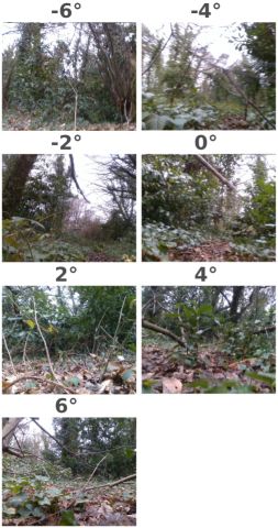
Fig. 10.     Sample results for depth estimation. Results from a U-net
                                                                           [19] trained with 8204 RGB-depth image pairs. In the depth images (right
                                                                           column), pixels without vaild depth information are indicated in red. The
                                                                           U-net receives the RGB image in the left column as input and provides the
                                                                           depth estimation shown in the center column. The predicted depth map can
Fig. 9. Image instances for different pitch angles. Perspectives ranging
                                                                           be compared to the recorded depth image in the right column.
from -6◦ to 6◦ camera pitch angle.

                                                                                                    V. C ONCLUSIONS
                                                                              An off-road forest depth map dataset has been collated
Image Perspective: Approximately 15–25% of the image                       to support the development of computer vision modules for
frames in each video were taken with the camera tilted                     portable robots that operate in forests. Accordingly, it is
upwards and do not include the ground in the view. For                     recorded from a low viewpoint and with close-up views of
our purpose of training depths estimating neuronal networks,               obstacles such as fallen tree branches and shrubs. The data
such frames are helpful, because they do not have the direct               set is of sufficient size to train modern neuronal networks
correlation between distance and height (y-axis position) that             and is provided with metadata, that can, for example, be
is otherwise common. In applications where frames without                  used to filter the frames by camera orientation. We created
ground in view are undesirable, such frames can be excluded                this dataset with the primary aim to develop robots of
as follows. First the raw accelerometer and gyroscope data                 sufficiently low cost that sparse robot swarms [20] will
from the IMU as metadata for each frame, is fused to arrive at             become feasible. In this context, it is of interest to replace
an absolute orientation for the camera. Positive pitch values              depth cameras with estimated depth information from RGB
indicate a downward perspective, a threshold can be set to                 images. In ongoing work we are using the dataset to develop
discard frames in which the camera is tilted backwards. After              such depth prediction models particularly targeted at low
low-pass filtering the pitch angle of the camera [18], frames              capability embedded computers; a sample of what can be
without the ground in view can be discarded by filtering out               expected is shown in Fig. 10. We believe that the dataset is
frames with an angle below -4 degrees. Sample images at                    a first step to fill the gap of out-door datasets for small robots
different camera pitch are shown in Fig. 9. For convenience                and that it will be of use to the community. For example,
the pitch values—in a addition to the raw IMU data—have                    with the steering (rotary encoder) information available in
been included in the metadata of the forest depth dataset.                 the metadata, it may be possible to use the dataset to train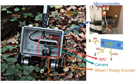
an autonomous guidance system. Hopefully this contribution
will stimulate computer vision research in the nascent and
challenging field of forest robotics.
                              R EFERENCES
 [1] M. Brambilla, E. Ferrante, M. Birattari, and M. Dorigo, “Swarm
     robotics: a review from the swarm engineering perspective,” Swarm
     Intelligence, vol. 7, no. 1, pp. 1–41, 2013.
 [2] H. Balta, G. De Cubber, D. Doroftei, Y. Baudoin, and H. Sahli,
     “Terrain traversability analysis for off-road robots using time-of-flight
     3d sensing,” in 7th IARP International Workshop on Robotics for Risky
     Environment-Extreme Robotics, Saint-Petersburg, Russia, 2013.
 [3] A. Bhoi, “Monocular depth estimation: A survey,” arXiv preprint
     arXiv:1901.09402, 2019.
 [4] H. W. Ho, G. C. de Croon, and Q. Chu, “Distance and velocity
     estimation using optical flow from a monocular camera,” International
     Journal of Micro Air Vehicles, vol. 9, no. 3, pp. 198–208, 2017.
 [5] R. Hartley and A. Zisserman, Multiple view geometry in computer
     vision. Cambridge, UK: Cambridge University Press, 2003.
 [6] D. Oram, “Rectification for any epipolar geometry,” in Proceedings
     of the British Machine Vision Conference (BMVC) 2001, T. F. Cootes
     and C. J. Taylor, Eds. British Machine Vision Association, 2001, pp.
     653–662.
 [7] C. Godard, O. Mac Aodha, and G. J. Brostow, “Unsupervised monoc-
     ular depth estimation with left-right consistency,” in Proceedings of
     the IEEE Conference on Computer Vision and Pattern Recognition,
     2017, pp. 270–279.
 [8] D. Xu, W. Wang, H. Tang, H. Liu, N. Sebe, and E. Ricci, “Structured
     attention guided convolutional neural fields for monocular depth
     estimation,” in Proceedings of the IEEE Conference on Computer
     Vision and Pattern Recognition, 2018, pp. 3917–3925.
 [9] D. Eigen, C. Puhrsch, and R. Fergus, “Depth map prediction from a
     single image using a multi-scale deep network,” in Advances in neural
     information processing systems, 2014, pp. 2366–2374.
[10] I. Laina, C. Rupprecht, V. Belagiannis, F. Tombari, and N. Navab,
     “Deeper depth prediction with fully convolutional residual networks,”
     in 2016 Fourth international conference on 3D vision (3DV). IEEE,
     2016, pp. 239–248.
[11] I. Alhashim and P. Wonka, “High quality monocular depth estimation
     via transfer learning,” arXiv preprint arXiv:1812.11941, 2018.
[12] A. Geiger, P. Lenz, C. Stiller, and R. Urtasun, “Vision meets robotics:
     The kitti dataset,” The International Journal of Robotics Research,
     vol. 32, no. 11, pp. 1231–1237, 2013.
[13] A. Valada, G. Oliveira, T. Brox, and W. Burgard, “Deep multispectral
     semantic scene understanding of forested environments using multi-
     modal fusion,” in International Symposium on Experimental Robotics
     (ISER), 2016.
[14] A. Saxena, M. Sun, and A. Y. Ng, “Make3d: Learning 3d scene
     structure from a single still image,” IEEE transactions on pattern
     analysis and machine intelligence, vol. 31, no. 5, pp. 824–840, 2008.
[15] ——, “Learning 3-d scene structure from a single still image,” in 2007
     IEEE 11th International Conference on Computer Vision. IEEE, 2007,
     pp. 1–8.
[16] M. Firman, “RGBD datasets: Past, present and future,” in Proceedings
     of the IEEE conference on computer vision and pattern recognition
     workshops, 2016, pp. 19–31.
[17] P. K. Nathan Silberman, Derek Hoiem and R. Fergus, “Indoor segmen-
     tation and support inference from RGBD images,” in ECCV, 2012.
[18] W. H. Press and S. A. Teukolsky, “Savitzky-Golay smoothing filters,”
     Computers in Physics, vol. 4, no. 6, pp. 669–672, 1990.
[19] O. Ronneberger, P. Fischer, and T. Brox, “U-net: Convolutional
     networks for biomedical image segmentation,” in International Confer-
     ence on Medical image computing and computer-assisted intervention.
     Springer, 2015, pp. 234–241.
[20] D. Tarapore, R. Groß, and K.-P. Zauner, “Sparse robot swarms:
     Moving swarms to real-world applications,” Frontiers in Robotics and
     AI, vol. 7, p. 83, 2020.
You can also read