Coverage of a shopping mall with flexible OLED-based visible light communications - vision itn
←
→
Page content transcription
If your browser does not render page correctly, please read the page content below
Research Article                                        Vol. 28, No. 7 / 30 March 2020 / Optics Express 10015

Coverage of a shopping mall with flexible
OLED-based visible light communications
Z AHRA N AZARI C HALESHTORI , 1,* S TANISLAV Z VANOVEC , 1 Z ABIH
G HASSEMLOOY, 2 H OSSIEN B. E LDEEB , 3 AND M URAT U YSAL 3
1 Department  of Electromagnetic Field, Faculty of Electrical Engineering, Czech Technical University in
Prague, Prague 16627, Czech Republic
2 Optical Communications Research Group, Faculty of Engineering and Environment, Northumbria
University, Newcastle-upon-Tyne NE1 8ST, UK
3 Department of Electrical and Electronics Engineering, Ozyegin University, Istanbul 34794, Turkey
* nazarzah@fel.cvut.cz

Abstract: Visible light communications (VLC) can utilize light-emitting diodes (LEDs) to
provide illumination and a safe and low-cost broadcasting network simultaneously. In the past
decade, there has been a growing interest in using organic LEDs (OLEDs) for soft lighting and
display applications in public places. Organic electronics can be mechanically flexible, thus the
potential of curved OLED panels/displays devices. This paper provides unique characteristics
of a flexible OLED-based VLC link in a shopping mall. We show that, for curved OLED the
radiation pattern displays a symmetry, which is wider than Lambertian. A number of scenarios
of VLC system with flexible OLED are analyzed. Numerical models for the delay spread and
optical path loss are derived, which followed a 2-term power series model for both empty and
furnished rooms. We show that using a full-circular OLED for both empty and furnished rooms
offers a uniform distribution of emitted power for the same transmission link spans. The link
performance using full and half-circular OLED in an empty room shows that the average optical
path losses are lower by 5 and 4 dB, compared with the furnished room.

© 2020 Optical Society of America under the terms of the OSA Open Access Publishing Agreement

1.   Introduction
Visible light communications (VLC) provide illumination and wireless data transmission through
the free space at the same time via intensity modulation of the light source [1,2]. In VLC, both
the conventional silicon-based light-emitting diodes (LEDs) and organic-based LEDs (OLEDs),
which are widely used as lamps and panels in homes, public places and offices, can be adopted
[3,4]. In this work, we only consider OLEDs, where the emissive electroluminescent layer is
a film of organic compounds, are thinner, lighter and more flexible than the crystalline layers
in LEDs or liquid crystal display (LCD) devices [5]. With improved technologies and reduced
fabrication and manufacturing costs, OLEDs offer an advantage over the conventional LEDs and
other lighting technologies including self-emission, brighter with rich colors, biodegradable,
wide beam angle, simple and flexible structure, with no need for backlighting and large active
areas [6,7]. However, OLEDs are costly to produce with shorter lifetimes (in particular blue
organics) and can be damaged by water. In addition, OLEDs have a low modulation bandwidth
Bmod of hundreds of kHz compared with solid-state LEDs (a few MHz), which are due to the
carrier lifetime and the parasitic resistor-capacitor (RC) effects [8]. An exciting feature of OLED
panels is the potential of using flexible substrates to make lights that can be curved, rolled or
folded.
   Note, in VLC wavelength-dependence channel modeling, it is important to consider the
reflectance properties of the materials and objects within the indoor environments. To determine
channel impulse response (CIR) of VLC systems, a number of research activities have been
reported, which emphasize the use of inorganic LEDs. For instance, in [9], to find CIR of the

#389814                                                                       https://doi.org/10.1364/OE.389814
Journal © 2020           Received 5 Feb 2020; revised 11 Mar 2020; accepted 11 Mar 2020; published 23 Mar 2020
Research Article                                 Vol. 28, No. 7 / 30 March 2020 / Optics Express 10016

VLC system in an empty room, Monte Carlo ray-tracing method was adopted considering up to 3
reflections. However, the majority of published works do not consider the wavelength dependency
of the channel. Works in [10,11] used recursive calculation methods [12] to determine CIR of an
empty room without considering wavelength dependency. In [13], Barry’s model by including
wavelength-dependent white LED characteristics and spectral reflectance of indoor reflectors
was generalized and up to 4 reflections are considered to model indoor multipath dispersion
characteristics for VLC. Next, in [14], Barry’s model was compared with channel modeling
results obtained using a commercial optical and illumination design software Zemax [15] and
the approach yielded the same CIR as in [13]. In this approach, a larger number of reflections
and the wavelength-dependency of the materials can be included and it has been endorsed as
a reference channel model for upcoming standards such as IEEE 802.15.7r1 [16]. In [17], for
VLC a three-dimensional (3D) simulation environment using a CAD software was model based
on Monte Carlo algorithm. In [18], flexible OLED lighting panel radiation pattern and its
impact on the VLC channel were investigated. It was shown that, compared with Lambertian
source, OLEDs are more flexible in terms of the radiation pattern control offering reduced root
mean square (RMS) delay spread and the average optical path loss (OPL) of 8.8% and 3 dB,
respectively.
   The use of curved OLED with a wider beam pattern than Lambertian for VLC for different
indoor scenarios has not been reported in the literature yet. Additionally, as the development of
organic technology is being increased at applications of large display panels and pixels used in
mobile devices, there is a significant potential to facilitate simultaneously illumination, display
with text message on it, and data communication via the display of screens provided in shopping
malls. In this paper, a flexible OLED used in a shopping mall is investigated by the means of
characterizing its illumination profile, spectrum and Bmod . For simulating the channel-specific
features, we have adopted ray tracing. The specific channel models in terms of OPL and RMS
delay spread are derived for four scenarios within the shopping mall. A full and half-circular
OLED are placed around the pillar in an empty and a furnished room with different size of
a transmitter (Tx) and varied locations of a receiver (Rx). In addition, the performance of
an OLED-based VLC link is investigated in terms of the bit error rate (BER). Using full and
half-circular OLEDs in an empty room, data rates Rb of 10 Mb/s and 3.7 Mb/s are achieved over
a line of sight (LOS) path of 6 m, respectively. The data rate is dropped to 1.02 Mb/s and 0.46
Mb/s in a furnished room, respectively.
   The rest of the paper is organized as follows. In Section 2, the principle of the VLC channel
and OLED specifics are described. Section 3 represents the main features of the simulation and
Section 4 discusses the results. Finally, conclusions are given in Section 5.

2.     Principle of VLC
2.1.    Channel characterization
The physical indoor VLC channel includes the effects of both LOS, where the LED is aligned
directly with the Rx, and non-LOS (NLOS), where the signal is captured via reflections from
walls, ceiling, etc., [19]. The regenerated electrical signal at the output of the optical Rx is given
as [1]:
                                     y(t) = γ · x(t) ⊗ h(t) + n(t),                                (1)
where x(t) is the emitted optical intensity, γ is the photodetector (PD) responsivity in (A/W), h(t)
is the CIR and ⊗ denotes convolution. n(t) represents the noise, which includes the quantum noise
from the optical signal, background radiation noise caused by the photons reception from ambient
light and noise from the Rx such as the dark current noise and the thermal noise. The background
radiation noise can be modeled as the signal independent additive white Gaussian noise (AWGN)
with one-sided power spectral density N0 due to its high intensity. The background radiation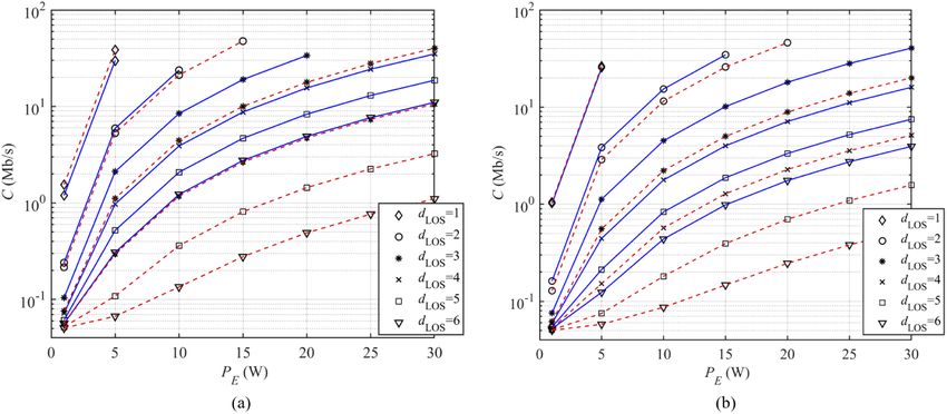
Research Article                                   Vol. 28, No. 7 / 30 March 2020 / Optics Express 10017

induced noise limits the received signal-to-noise ratio (SNR)Í since it is the dominant noise source
[20]. The CIR of the indoor channel can be written as Ni=1 ηi δ(t − τi ), where δ(t) is Dirac delta
function, τi is the time delay of the ith ray, ηi is the gain path of the ith ray and N is the number of
received rays [1]. We consider three criteria to quantify the limitation on the transmission rate
                                                                                             ∫∞
through the free space channel; channel gain and corresponding OPL = −10 log10 ( h(t)dt) in
                                                                                                −∞
dB, channel mean excess delay τ and the RMS delay spread τRMS , which are given as [14]:
                                         ∫∞
                                             t × h(t)dt
                                     τ = 0∫ ∞           ,                                (2)
                                           0
                                               h(t)dt
                                            v
                                            t∫ ∞
                                            u
                                               0
                                                    (t − τ)2 × h(t)dt
                                   τRMS =             ∫∞              .                                     (3)
                                                       0
                                                          h(t)dt
   The optical radiation pattern profile determines the spatial intensity distribution of light emitted
from the light source. The luminous intensity defined in terms of the angle of irradiance θ is
given as [1]:                                                   "         #
                                  mL + 1                            π   π
                           I(θ) =          I(0) cosmL (θ) θ = − , ,                                 (4)
                                     2π                             2 2
where I(0) is the center luminous intensity of the LED and mL is Lambertian order, which is
defined in terms of the Tx semi-angle θ 1/2 as [1]:

                                                      ln (2)
                                        mL = −                    .                                         (5)
                                                 ln [cos(θ 1/2 )]

2.2.     OLEDs
2.2.1.   Structure of OLEDs
OLED display devices use organic carbon-based films, sandwiched together between two charged
electrodes; one is a metallic cathode (aluminum or silver) and the other is a transparent anode
(indium tin oxide (ITO)), see Fig. 1 [21]. The organic materials can be long-chain polymers (i.e.,
PLEDs) or small organic molecules (i.e., SMOLEDs) in a crystalline phase. Note, OLEDs have
a low-pass filter transfer function with the cut-off frequency given by [1]:
                                                      1
                                             fc =         ,                                                 (6)
                                                    2πRCo

where R is the effective resistance of the OLED and Co = At d0 r is the plate capacitance, At is the
OLED photoactive area, d is the OLED thickness, and 0 and r are the permittivities of free
space and relative dielectric constant of the organic layer, respectively. Evidently, a larger area
photoactive will have a lower Bmod and hence a limitation on the maximum Rb in OVLC systems.
Flexibility and lower production cost of non-rigid OLEDs make them the light source for future
applications. The curved or rolled OLED panels/displays can be used in wearable products (such
as wearable smart watches and computers), mobile phones, TVs, vehicles, trains, etc.

2.2.2.   Characterization of a flexible OLED
A flexible OLED (UNISAGA, the size of 200 × 50 mm2 ) was characterized in terms of the beam
pattern and the spectrum profile, which were then used as the inputs for further simulations.
Figure 2(a) illustrates the measured normalized optical spectrum of a flexible OLED at different
bias currents IB [22], which shows the peak wavelengths of 620 nm (Red), 553 nm (Green), 454
Research Article                                     Vol. 28, No. 7 / 30 March 2020 / Optics Express 10018

                                        Fig. 1. OLED structure

nm and 480 nm (Blue). The intensity profiles of a flexible OLED for three different configurations
are depicted in Fig. 2(b), showing symmetry around 0◦ but not fitting Lambertian radiation pattern
(the solid blue line for mL = 1). Note, the radiation angle θ 1/2 ranges are 58◦ , 65◦ , 75◦ , and 90◦
for the flat, quadrature-circle, half-circle and three quadrature-circle of light panels, respectively.
Note that, non-Lambertian emitters can also be considered by Monte Carlo approaches [23].
Instead of a typical Lambertian profile, in the simulation we have used the measured radiation
pattern for the curved OLED, which is wider than Lambertian pattern.

       Fig. 2. Characteristics of the flexible OLED adopted in the work: (a) the normalized optical
       spectrum of the flexible OLED. The peak wavelengths is marked and the legend color scale
       represents IB [22]. (b) The intensity pattern of OLED panel bent in different curvature such
       that we have a quadrature, half and three-quadrature-circle of lighting.

3.   Modeling flexible OLED-based VLC within the mall scenario
Figure 3 illustrates the steps adopted in this work for channel modeling. First, an indoor
environment or a 3D scene such as office, hospital, store, etc., with specified geometry, shape and
with objects is created. This is followed by including the main system parameters for reflection
coefficients of different surfaces, and location of light sources and detectors. We have adopted
the non-sequential ray tracing feature of Zemax to specify the number of rays, the detected power
and the path lengths for each ray. The output data are then imported to Matlab for processing to
determine the CIR.
   The organic light sources are being widely used in large area including shopping malls, airport,
etc, because of flexibility, smooth lighting, etc. Thus the reason why a shopping mall is being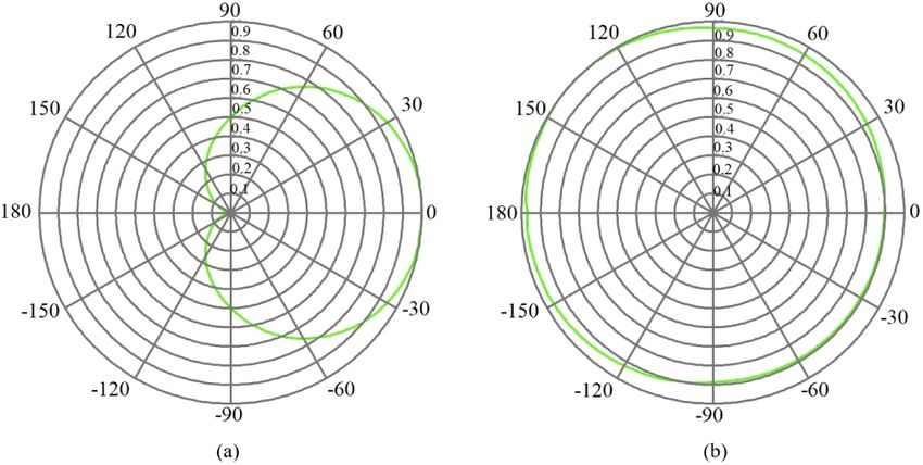
Research Article                                  Vol. 28, No. 7 / 30 March 2020 / Optics Express 10019

                Fig. 3. The major steps followed in the channel modeling methodology.

considered in this work, which can be adopted in other application areas. Figure 4(a) shows
a 10 × 10 × 3 m3 size store with a number of objects. Note, the use of curved OLED on the
pillar, which is composed of 38 OLED panels 64-chip and with a chip radiating power of 4.1
mW and a total power of 10 W. The size of OLED was set as 2 × 0.5 m2 . In the model, we
adopted measured beam patterns for the curved OLED, see Fig. 5. The reflectance values as a
function of the wavelength for a range of surfaces, materials, etc., are shown in Fig. 6, which
is adopted from [13,24]. Note that, the specular reflection case is used when materials have
specified regular surfaces, which reflect the rays in particular directions and hence the use of
Phong model [17,25]. Although specular reflections can occur from shiny objects, in nature
(e.g., shopping mall area), where materials have irregular surfaces and rays are reflected in all
directions, the resultant reflection pattern is mostly diffuse in nature that can be modeled as
Lambertian [13,26,27]. Therefore, the reflections from materials are assumed to be purely diffuse.
The Rx is positioned at the height of 1.3 m above the floor level (i.e., the holding position of
mobile by people) while the user is facing OLED and its location is varied on the diagonal, which
stretches from the corner to the middle of the room. The distance between the Tx and the Rx
can be within the range of 0.5 m < dLOS < 6 m. Note, the dimension of the user considered is
25 × 50 × 180 cm3 .
   We have considered 4 scenarios of (i) a full-circular OLED panel around the pillar in an
empty (S1 ) and a furnished room (S2 ), see Fig. 4(b); and (ii) a half-circular OLED panel (size
of 1 × 0.5 m2 ) in an empty room (S3 ) and in a furnished room (S4 ), see Fig. 4(c). Here, we
have adopted Monte Carlo analysis and Sobol sampling as the random ray-tracing methods. The
number of reflections was set based on the simulation of particular ray propagation, where the
normalized intensity dropped to 10−3 . All other key system parameters are given in Table 1.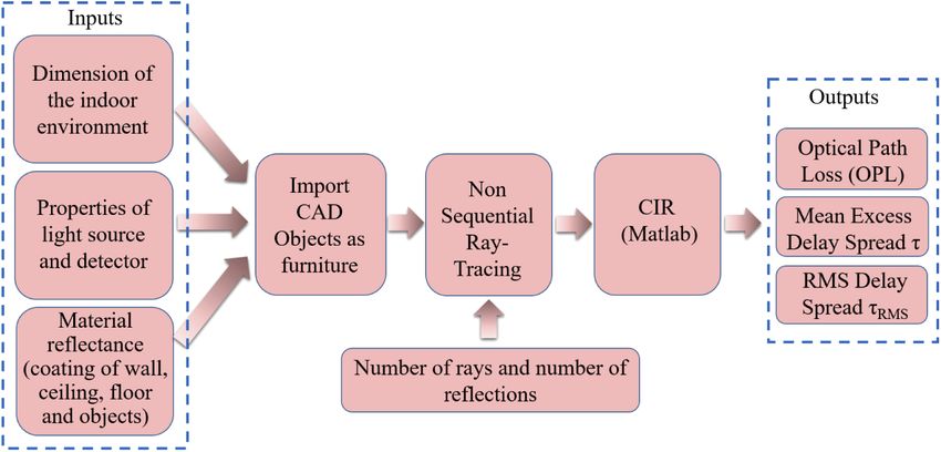
Research Article                                     Vol. 28, No. 7 / 30 March 2020 / Optics Express 10020

 Fig. 4. (a) The three-dimensional indoor environment in Zemax and proposed scenarios;
 showing the location of curved OLED giving (b) a full-circular lighting and (c) a half-circular
 lighting.

 Fig. 5. Emission pattern of the light source used in simulation for: (a) a half-circular OLED
 and (b) a full-circular OLED.
Research Article                                          Vol. 28, No. 7 / 30 March 2020 / Optics Express 10021

                 Fig. 6. Spectral reflectance of various materials used in simulation [13,24].

                                Table 1. System and Simulation Parameters
Item                                      Parameter                                            Value
Room                                      Size                                                 10 × 10 × 3m3
                                          Radius of pillar                                     33 cm
Reflections specifications                Type of reflections                                  Purely diffuse
                                          Number of reflections                                4
                                          Material reflectance                                 Wavelength-dependent
Coating material                          Walls and pillar                                     Plaster
                                          Desks and chair                                      Pine wood
                                          Couch, shoes, and bags                               Leather
                                          Laptop                                               Black gloss paint
                                          Coffee cup                                           Ceramics
                                          Clothes                                              Cotton
Tx                                        Dimension                                            2 × 0.5m2
                                          Type                                                 Flexible OLED
                                          Bandwidth                                            50 kHz
                                          Power of lighting                                    10 W
                                          Number of OLED panels                                38
                                          Number of chip per each panel                        64
                                          Power of each chip                                   4.1 mW
                                          Location on pillar                                   Fixed (Middle of store)
Channel                                   Length dLOS                                          1 m to 6 m
                                          Resolution time                                      0.2 ns
Rx                                        Active area of PD                                    1 cm2
                                          FOV angle                                            90◦
                                          Responsivity                                         0.4 A/W
                                          N0                                                   10−21 W/Hz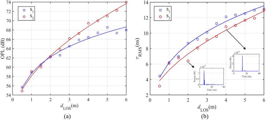
Research Article                                    Vol. 28, No. 7 / 30 March 2020 / Optics Express 10022

4.     Results
The results from analyzes are discussed in this section.

4.1.    CIR characteristics
The channel OPL can be used to specify the required emitting power of light source to meet the
BER target. At first we make a comparison of inorganic LED and OLED sources with the results
shown in Fig. 7. As can be seen, for the LED, OPL is increased by ∼ 5 dB compared with S4 .
In addition, τRMS for S4 in considerably lower than LED-based VLC. Note, the main purpose,
however, was to provide comparison of the utilization of curved OLEDs.

        Fig. 7. Comparison of inorganic LED with half-circular OLED (i.e., S4 ) in the furnished
        room in term of: (a) OPL and (b) τRMS .

   Figure 8(a) shows OPL distributions of the curved OLED sources for S1 and S2 . The OPL
increases with the LOS path reaching maximum values of 69 and 74 dB at dLOS of 6 m for S1 and
S2 , respectively. For S2 , OPL is higher compared with S1 due to the lower reflection coefficients
of the objects within the room. It can be seen that, for dLOS > 4 m, there is a huge difference in
the received power between the empty and furnished rooms. E.g., the OPL penalties are 2.6, 3.8

        Fig. 8. Comparison of empty and furnished room where a full-circular OLED is employed
        (i.e., S1 and S2 ) in term of: (a) OPL and (b) τRMS . The CIR plots for distance of 2 m and 4
        m are shown in inset.
Research Article Vol. 28, No. 7 / 30 March 2020 / Optics Express 10023
and 4.9 dB for dLOS of 4, 5 and 6 m, respectively. As an example, CIR plots for dLOS of 2 and
4 m are shown in insets of Fig. 8(b) depicting τRMS as a function of dLOS for S1 and S2 . Note,
τRMS increases with dLOS reaching maximum values of 13.55 and 12.85 ns at the corner for S1
and S2 , respectively.
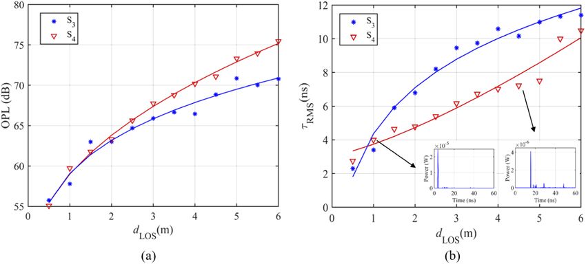
Figure 9 shows OPL and the delay spread as a function of dLOS for S3 and S4 when using a
half-circular OLED in empty and furnished rooms, which are higher and lower, respectively,
compared with Fig. 8 for a given dLOS . In an empty room, OPL reaches the maximum of 71
dB, which is lower than the value corresponding to S4 (75 dB). As a result of the comparison
between scenarios of S2 and S4 OPL decreases at the cost of increasing τRMS , where a full-circular
OLED is employed in a furnished room compared with a half-circular OLED. The OPL penalty
improvement is approximately 1.6 dB.
Fig. 9. Comparison of empty and furnished room where a half-circular OLED is employed
(i.e., S3 and S4 ) in term of: (a) OPL and (b) τRMS . The CIR plots for distance of 1 m and
4.5 m are shown in inset.
Based on numerical modeling, we have derived empirical models for dLOS and τRMS . For all
cases the delay spread is obtained by fitting a 2-term power series model, which is given as:
t2
τRMS = t1 dLOS + t3 , (7)
where t1 , t2 and t3 for the scenarios considered here are summarized in Table 2. In addition, for
all cases using the 2-term power series models we have:
o2
OPL = o1 dLOS + o3 , (8)
where the parameters o1 , o2 and o3 are given in Table 3. Note, the main aim of this paper is to
investigate the behavior/trends of OPL and τRMS and show that the empirical parameters, which
are valid for the specific room size, can vary based on the number of objects in the room and the
room-size.
Table 2. Numerical modeling parameters for τRMS in all proposed scenarios (S1 , S2 , S3 , S4 ).
Scenario t1 t2 t3
S1 6.2500 0.4381 1.156 × 10⁻⁹
S2 5.1972 0.5017 7.462 × 10⁻⁹
S3 4.5961 0.5481 1.468 × 10⁻¹²
S4 0.6643 1.3132 3.0756Research Article Vol. 28, No. 7 / 30 March 2020 / Optics Express 10024
Table 3. Numerical modeling parameters for OPL in all proposed scenarios (S1 , S2 , S3 , S4 ).
Scenario o1 o2 o3
S1 29.59 0.1618 29.13
S2 9.568 0.5378 48.59
S3 29.07 0.1905 30.00
S4 13.43 0.4414 45.56
4.2. System performance
The BER performance of the proposed system with non-return-to-zero (NRZ) on-off keying
(OOK) is shown in Fig. 10. Also shown is the 7% forward error correction (FEC) BER limit
of 3.8 × 10⁻³ . For S1 , the BER plots are below the FEC limit for dLOS up to 6 m with Rb of 10
Mb/s. For S2 , BER values lower than the FEC are achieved at dLOS of < 4 m with Rb of up to
10 Mb/s. In addition, Rb values are 3.04 and 1.02 Mb/s for dLOS of 5 and 6 m, respectively for
S2 . Figure 10(b) depicts the BER for S3 and S4 , where S3 shows improved performance over a
longer distance compared with S4 . It can be seen that, for S3 the BER remains just below the
FEC limit for dLOS < 4 m and at dLOS of 5 and 6 m the achieved Rb values are 7.05 and 3.7 Mb/s,
respectively. For S4 , the BER is also below the FEC limit for dLOS of < 3 m with Rb of 10 Mb/s.
Additionally, Rb values are 4.82, 1.48 and 0.46 Mb/s for dLOS of 4, 5 and 6 m, respectively.
Fig. 10. The BER performance versus Rb for different dLOS in cases of: (a) S1 (solid blue
line), S2 (dashed red line) and (b) S3 (solid blue line), S4 (dashed red line).
Figure 11 illustrates the channel capacity C versus the transmit optical power PE for a range of
dLOS at Rb of 4 Mb/s and Bmod of 50 kHz for S1 -S4 . It can be seen that, C increases with respect
to PE . E.g., for S2 , at dLOS of 3 m we observe C of 4.46 and 17.83 Mb/s at PE of 10 and 20 W,
respectively. Obviously, for the same PE a significant drop in C can be seen with increased dLOS ;
e.g., for S1 , at PE of 10 W, C drops from 23.78 to 1.23 Mb/s for dLOS of 2 and 6 m, respectively.
For S1 , it is observed that for dLOS < 3 m and PE > 20 W, C is higher than 100 Mb/s. For S3 and
S4 , we observe the same trend for C as in Fig. 11(a), see Fig. 11(b). It can be seen that, for the
same dLOS , almost similar channel capacity can be achieved with lower emitted optical power in
the case of S2 compared with S4 as the light source dimension increases. E.g., at dLOS of 3 m,
C of 10 Mb/s can be achieved for power levels of 15 and 22 W for S2 and S4 , respectively. As
a result of the comparison between all scenarios; e.g., at a given PE of 20 W and dLOS of 4 m,
we have C of 15.58, 4.71, 7.11 and 2.28 Mb/s for S1 to S4 , respectively. Therefore, there is aResearch Article Vol. 28, No. 7 / 30 March 2020 / Optics Express 10025
significant drop in C for the case of furnished room compared with an empty room, regardless of
using a full or a half-circular OLED.
Fig. 11. The channel capacity versus PE for different dLOS at Rb of 4 Mb/s and Bmod of 50
kHz for: (a) S1 (solid blue line), S2 (dashed red line) and (b) S3 (solid blue line), S4 (dashed
red line).
5. Conclusion
In this paper, we proposed a flexible OLED as the Tx in a VLC system to cover the shopping
mall. We carried out the characterization of the OLED in terms of the spectrum profile and
optical irradiation pattern as part of the simulation modeling of the light source. The beam
pattern of a curved OLED was found to be symmetrical about the origin while being wider
than Lambertian radiation pattern. This feature offers the benefit of maintaining the same SNR
over a given transmission radius of curved OLED. The increasing use of flexible OLED in
thin-film devices (such as wearable devices, mobile phones, TVs) acts as a good motivator to
investigate the performance of a VLC system based on these devices. The results of utilizing a
full-circular OLED for both empty and furnished rooms showed a uniform distribution of emitted
power for the same transmission link spans. We showed that for full and half-circular OLEDs
adopted in an empty room, the link performance improved with the average OPL penalties of 5
and 4 dB compare with the corner of a furnished room. The numerical models of τRMS were
derived, which followed a 2-term power series model for both the empty and furnished rooms.
In addition, the OPL profile models were derived for all proposed scenarios. Furthermore, the
link’s BER performance and the channel capacity were investigated. For an empty room with
full and half-circular OLEDs, Rb of 10 and 3.7 Mb/s were achieved at dLOS of 6 m, respectively.
In addition, in a furnished room with a full-circular OLED, Rb of 10, 3.04 and 1.02 Mb/s were
recorded for dLOS of 4, 5 and 6 m, respectively, which are two times higher than the values when
using a half-circular OLED (i.e., 4.82, 1.48 and 0.46 Mb/s). As a result, for a given dLOS the
same channel capacity can be obtained with lower emitted optical power using a full-circular
light source compared with a half-circular OLED.
Funding
H2020 Marie Skłodowska-Curie Actions (VisIoN 764461).Research Article Vol. 28, No. 7 / 30 March 2020 / Optics Express 10026
Disclosures
The authors declare no conflicts of interest.
References
1. Z. Ghassemlooy, L. N. Alves, S. Zvanovec, and M.-A. Khalighi, Visible light communications: theory and applications
(CRC press, 2017).
2. Z. Ghassemlooy, W. Popoola, and S. Rajbhandari, Optical wireless communications: system and channel modelling
with Matlab® (CRC press, 2019).
3. B. Lin, Z. Ghassemlooy, C. Lin, X. Tang, Y. Li, and S. Zhang, “An indoor visible light positioning system based on
optical camera communications,” IEEE Photonics Technol. Lett. 29(7), 579–582 (2017).
4. S. Schmid, T. Richner, S. Mangold, and T. R. Gross, “Enlighting: An indoor visible light communication system
based on networked light bulbs,” in 2016 13th Annual IEEE International Conference on Sensing, Communication,
and Networking (SECON), (IEEE, 2016), pp. 1–9.
5. B. Geffroy, P. Le Roy, and C. Prat, “Organic light-emitting diode (oled) technology: materials, devices and display
technologies,” Polym. Int. 55(6), 572–582 (2006).
6. J. Clark and G. Lanzani, “Organic photonics for communications,” Nat. Photonics 4(7), 438–446 (2010).
7. J. Ràfols-Ribé, P.-A. Will, C. Hänisch, M. Gonzalez-Silveira, S. Lenk, J. Rodríguez-Viejo, and S. Reineke,
“High-performance organic light-emitting diodes comprising ultrastable glass layers,” Sci. Adv. 4(5), eaar8332
(2018).
8. Z. H. Kafafi, Organic electroluminescence (CRC Press, 2018).
9. H. Chun, C.-J. Chiang, and D. C. O’Brien, “Visible light communication using oleds: Illumination and channel
modeling,” in 2012 International Workshop on Optical Wireless Communications (IWOW), (IEEE, 2012), pp. 1–3.
10. H. Nguyen, J.-H. Choi, M. Kang, Z. Ghassemlooy, D. Kim, S.-K. Lim, T.-G. Kang, and C. G. Lee, “A matlab-based
simulation program for indoor visible light communication system,” in 2010 7th International Symposium on
Communication Systems, Networks & Digital Signal Processing (CSNDSP 2010), (IEEE, 2010), pp. 537–541.
11. T. Komine and M. Nakagawa, “Performance evaluation of visible-light wireless communication system using white
led lightings,” in Proceedings. ISCC 2004. Ninth International Symposium on Computers And Communications
(IEEE Cat. No. 04TH8769), vol. 1 (IEEE, 2004), pp. 258–263.
12. J. R. Barry, J. M. Kahn, W. J. Krause, E. A. Lee, and D. G. Messerschmitt, “Simulation of multipath impulse response
for indoor wireless optical channels,” IEEE J. Select. Areas Commun. 11(3), 367–379 (1993).
13. K. Lee, H. Park, and J. R. Barry, “Indoor channel characteristics for visible light communications,” IEEE Commun.
Lett. 15(2), 217–219 (2011).
14. F. Miramirkhani and M. Uysal, “Channel modeling and characterization for visible light communications,” IEEE
Photonics J. 7(6), 1–16 (2015).
15. Zemax OpticStudio 18.9, https://www.zemax.com/products/opticstudio.
16. M. Uysal, F. Miramirkhani, O. Narmanlioglu, T. Baykas, and E. Panayirci, “Ieee 802.15. 7r1 reference channel
models for visible light communications,” IEEE Commun. Mag. 55(1), 212–217 (2017).
17. S. P. Rodríguez, R. P. Jiménez, B. R. Mendoza, F. J. L. Hernández, and A. J. A. Alfonso, “Simulation of impulse
response for indoor visible light communications using 3d cad models,” J Wireless Com Network 2013(1), 7 (2013).
18. H. Chen and Z. Xu, “Oled panel radiation pattern and its impact on vlc channel characteristics,” IEEE Photonics J.
10(2), 1–10 (2018).
19. S. Long, M.-A. Khalighi, M. Wolf, Z. Ghassemlooy, and S. Bourennane, “Performance of carrier-less amplitude
and phase modulation with frequency domain equalization for indoor visible light communications,” in 2015 4th
International Workshop on Optical Wireless Communications (IWOW), (IEEE, 2015), pp. 16–20.
20. Z. Wang, Q. Wang, W. Huang, and Z. Xu, Visible light communications: Modulation and signal processing (John
Wiley & Sons, 2017).
21. J. Kalinowski, Organic Light-Emitting Diodes: Principles, Characteristics & Processes (CRC press, 2018).
22. Z. N. Chaleshtori, A. Burton, Z. Ghassemlooy, and S. Zvanovec, “A flexible oled based vlc link with m-cap
modulation,” in 2019 15th International Conference on Telecommunications (ConTEL), (IEEE, 2019), pp. 1–6.
23. H. B. Eldeeb, F. Miramirkhani, and M. Uysal, “A path loss model for vehicle-to-vehicle visible light communications,”
in 2019 15th International Conference on Telecommunications (ConTEL), (IEEE, 2019), pp. 1–5.
24. ASTER Spectral Library-Version 2.0, http://speclib.jpl.nasa.gov.
25. S. Lee, J. K. Kwon, S.-Y. Jung, and Y.-H. Kwon, “Evaluation of visible light communication channel delay profiles
for automotive applications,” J Wireless Com Network 2012(1), 370 (2012).
26. C. R. Lomba, R. T. Valadas, and A. de Oliveira Duarte, “Efficient simulation of the impulse response of the indoor
wireless optical channel,” Int. J. Commun. Syst. 13(7-8), 537–549 (2000).
27. C. R. Lomba, R. T. Valadas, and A. de Oliveira Duarte, “Experimental characterisation and modelling of the reflection
of infrared signals on indoor surfaces,” IEE Proc.: Optoelectron. 145(3), 191–197 (1998).You can also read