Modeling Cable-Driven Joint Dynamics and Friction: a Bond-Graph Approach - DLR
←
→
Page content transcription
If your browser does not render page correctly, please read the page content below
2020 IEEE/RSJ International Conference on Intelligent Robots and Systems (IROS)
October 25-29, 2020, Las Vegas, NV, USA (Virtual)

                                    Modeling Cable-Driven Joint Dynamics
                                    and Friction: a Bond-Graph Approach
                        Daniele Ludovico1,2 , Paolo Guardiani1,2 , Alessandro Pistone2 , Jinoh Lee3 ,
                             Ferdinando Cannella2 , Darwin G. Caldwell2 and Carlo Canali2

   Abstract— Cable-driven joints proved to be an effective
solution in a wide variety of applications ranging from medical
to industrial fields where light structures, interaction with
unstructured and constrained environments and precise motion
are required. These requirements are achieved by moving the
actuators from joints to the robot chassis. Despite these positive
properties a cable-driven robotic arm requires a complex cable
routing within the entire structure to transmit motion to all
joints. The main effect of this routing is a friction phenomenon
which reduces the accuracy of the motion of the robotic device.
In this paper a bond-graph approach is presented to model a
family of cable-driven joints including a novel friction model
that can be easily implemented into a control algorithm to
compensate the friction forces induced by the rope sliding into
bushings.                                                                    Fig. 1. Schematic of the cable-driven joint family considered in this work.

                         I. I NTRODUCTION
   The most interesting characteristic of a cable-driven mech-               to define a precise model for cable-driven mechanism which
anism is the option to move actuators from joints to chassis                 considers also friction phenomena.
reducing the overall weight of the moving structure and                         This work focuses on modeling a family of cable-driven
increasing the payload capability of the robot. This property                joints in which the cable routing along the structure has been
makes possible to assemble several joints together into a                    fulfilled through bushings as shown in Fig 1. The bond-
hyper-redundant manipulator able to move into wide, but                      graph approach [10], a graphical modeling technique, has
constrained environments. Furthermore, the presence of ca-                   been selected to determine the dynamic equations of the
bles introduces compliance in motion transmission increasing                 mechanism. Even if the bond-graph features fit perfectly
the safety of interaction with unstructured environments.                    with cable-driven mechanisms there are few examples of
All these attributes promote the cable-driven mechanism to                   such mechanisms modeled through bond-graph [11]. This
widespread in many applications. In medical field, where                     approach allows to separately analyse the different parts
accurate motion, dexterity and safe interaction are crucial                  constituting the mechanism to better understand the phenom-
aspects, the cable-driven mechanism is adopted to realise                    ena involved in each subsystem. A complete simulation of
system for minimally invasive surgery [1]. In industrial fields,             the whole system can be obtained connecting together each
cable-driven mechanisms appear in various application rang-                  subsystem through power bonds. In this modeling framework
ing from a parallel robot for logistics [2] to hyper-redundant               it is easy to understand how the friction forces act and
robots for the inspection of complex and constrained devices                 consequently how to include them in the dynamic equations.
[3]–[5] or maintenance in harsh environment [6]–[8] that                        Friction is one of classic, yet challenging problems in
cannot be reached by humans. In bio-inspired robots cable                    practical system modeling. Several friction models have
driven mechanism are often used to mimic limb tendons [9].                   been defined in literature: static friction model consists in
   One of the drawback of such mechanisms is the necessity                   a combination of Coulomb, viscous, stiction and Stribeck
to route the cables all along the structure complicating the                 terms, and an accurate description of friction is given by
design and introducing friction due to their interaction with                dynamic models such as Dahl or LuGree friction model [12].
bushing and pulleys. Requirements on motion accuracy lead                    For cable-driven mechanisms, friction forces produced by
                                                                             pulleys can be modeled as a function of the cable tension,
  1 Authors are with Department of Informatics, Bioengineering, Robotics
                                                                             velocity, wrap angle and number of pulleys [13]. An attempt
and System Engineering, University of Genoa, 16126, GE, Genoa                to define a general formulation for multi-node sliding cable
daniele.ludovico@iit.it
   2 Authors are with Advanced Robotics Department, Istituto Italiano di     is presented in [14]. To describe the friction force produced
Tecnologia (IIT), 16163, GE, Genoa, Italy                                    by sliding rope into bushing a modified version of the Dahl’s
   3 J. Lee is currently with the Institute of Robotics and Mechatronics
                                                                             model has been proposed [15]. However, aforementioned
Center, German Aerospace Center (DLR), 82234 Weßling, Germany. He
was with the Advanced Robotics Department, Istituto Italiano di Tecnologia   models are not able to correctly describe the friction forces
(IIT), 16163 Genoa, Italy                                                    generated by cables sliding into bushings or are too complex

978-1-7281-6211-9/20/$31.00 ©2020 IEEE                                   7285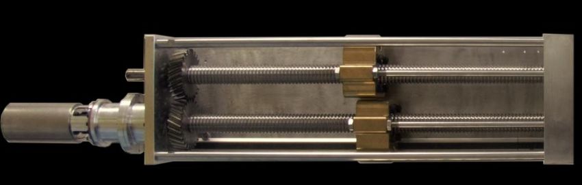
Sf : Va 0 Sf : Vj
1
R: c 1 C: K
Fig. 2. General bond graph representation of a cable driven joints.
Fig. 4. Bond graph describing the cable model.
Se : Fr1
−N
.. s
I: Lm Se : τf TF 1
k..m Ng Se : Fa1
..
Se : V 1 GY 1 TF 1
Se : Fr2
R: Rm I: Jm R: cm T..F 1
Ns
Se : Fa2
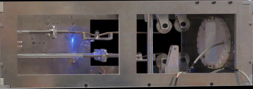
Fig. 5. Cable driven joint tested during the experiments.
Fig. 3. Bond graph describing the linear actuator model.
displacements. Finally each subsystem can be connected to
each other to obtain a complete simulation of the mechanism.
to be easily implemented in a real time controller.
In this work a real cable-driven joint has been considered
In this paper a novel method to model the friction of a to validate the proposed model. The following subsections
cable sliding into a bushing is proposed; the aim is to define a present the bond-graph model for each subsystem of the
simple model that can accurately describe the friction forces selected cable-driven joint.
of sliding cable to eventually improve the performances of a
real time control algorithm for cable-driven mechanism. An A. Actuator Model
hardware prototype has been used to validate the proposed The linear actuator under test is made by a geared brush-
model. The remainder of this paper is organised as follows: less DC motor that moves two parallel ball nuts at the
in Section II the bond-graph modeling approach for cable- same speed but in opposite direction. From the bond-graph
driven joints is presented and the dynamic equations of the illustrated in Fig. 3, it is possible to derive the state space
system are derived. In Section III the mathematical friction representation of the linear actuator as
model for cables sliding into bushing is presented. Section IV
presents the hardware setup and the experimental tests per- Rm km
ẋ1 = − x1 − x2 + V,
formed to identify the sliding rope friction coefficients, and Lm Jm
the simulation results are compared with the real device km cm (1)
ẋ2 = x1 − x2 + τf + Ng Ns (∆Fr + ∆Fa ) ,
behaviour. In Section V the conclusion is drawn and future Lm Jm
works are listed. ẋ3 = x2 ,
where x1 , x2 and x3 are the state variable representing
II. B OND - GRAPH M ODELING OF C ABLE D RIVEN
respectively the flux linkage, the angular momentum and
M ECHANISM
the integral of the angular momentum of the motor, V
A cable-driven joint can be seen as the connection of three represents the voltage applied to the motor, τf is the gear
macro subsystems: a certain number of actuators, several friction torque, which can be experimentally determined
cables and a joint mechanism. The physical connection trough an identification procedure described in Section IV,
among them can be represented in terms of generalised ∆Fr = Fr1 − Fr2 is the force applied by the cables and
efforts (e) and flows (f ) as illustrated in Fig. 2. ∆Fa = Fa1 − Fa2 is the friction force produced by the
In this scenario the bond-graph approach allows to define sliding cables, which is described in Section III. The actuator
a model for each of these subsystems separately making parameters are listed in Table I.
easier the understanding of the main phenomena involved
in all these parts isolating them to define identification B. Cable Model
procedures to estimate uncertain parameters such as friction The cables selected in this work are made by a synthetic
or stiffness. Furthermore this technique makes it easy to fibre called Zylon. While this material shows a non linear
substitute different models of the same subsystem so as to behaviour for low tension, under the assumption that the
favor the accuracy or the speed of the simulation. From preload is sufficiently high, it is possible to approximate the
the graphical representation of bond-graphs the dynamic cable model with a parallel between a linear spring and a
equations of each subsystem can be derived where the damper. Fig. 4 illustrates the equivalent bond-graph repre-
state variables are represented by generalized momenta and sentation of this model. The resulting state space description
7286I: m1 I: m2 TABLE I
ACTUATOR PARAMETERS NOMINAL VALUES
Ṗcm2 x Ṗeex
Ṗcm1 x 1 0 1 0 1 Symbol Value Unit Description
Actuator Parameters
d11 S1 : T F T F : d12 S1 −d21 S2 : T F T F : −d22 S2 Lm 0.471 mH Motor inductance
Rm 0.444 Ω Motor resistance
cm 10.319 mN m/s Motor viscous friction
Se : F1 Se : F2 Jm 349.88 gcm2 Total inertia
km 102.4 mN m/A Motor torque constant
θ̇ Ngear 1 : 80 Gear reduction ratio
I: J1 1 rC1 : T F T F : rC1 1 I: J2 Nscrew 5 mm Screw pitch
Joints Parameters
m1 0.217 kg 1st link mass
1
J1 0.0007 kgm2 1st link inertia
m2 0.806 kg 2nd link mass
d11 C1 : T F T F : d12 C1 0 −d21 C2 : T F T F : −d22 C2 J2 0.00016 kgm2 2nd link inertia
d11 47 mm O1 P cm
1
d12 103 mm O2 P cm
1
Ṗcm1 y 1 0 1 0 1 d21 12 mm O2 P cm
Ṗcm2 y 2
Ṗeey d22 338 mm Pee P cm1
I: m1 I: m2 r 65 mm Anchor point distance
Fig. 6. Bond graph describing the joint model.
is defined by
ẋ4 = vj − va , (2)
where x4 is the state variable representing the elongation
of the cable, vj and va are linear velocity of the joint and
actuator, respectively. From the state equation (2) the forces Fig. 7. Schematic of the forces acting on a sliding cable.
applied by each cable can be computed as
Fr = Kx4 + c (vj − va ) , (3) Pee , respectively, and l1 = d11 + d12 and l2 = d21 + d22
represent the length of the first and second links.
where the stiffness K and internal damping c can be
The bond-graph depicted in Fig. 6 is obtained through (4).
estimated through an identification procedure described in
This gives the following dynamic equation:
Section IV.
−4m2 l1 d21 sin(θ) 2
J12
x5 + r cos (θ) ∆Fr + τg
C. Joint Model ẋ5 = , (5)
4J2 +m1 d211 +m2 (l12 +4l1 d21 cos(θ)+4d221 )
The selected cable-driven mechanism consists of two rigid 1+ J1
links and two parallel revolute joints whose rotation angles
where x5 denotes the state variable representing the angular
are constrained to be same through a gear system. Fig.
momentum of the joint, m1 , J1 , and m2 , J2 are respectively
5 shows the joint prototype, where O1 and O2 represent
the mass and inertia of the first and second links, r is the
respectively the first and second rotation axes, and Pcm1 and
distance of the cable anchor point from the center of the
Pcm2 are the center of mass (CoM) of the first and second
flange and τg is the torque due to gravity which is described
links, respectively, while Pee is the end effector position.
as
Pcm1 , Pcm2 and Pee are described by
τg = d11 cos (θ) Fg1 + (l1 cos (θ) + 2d21 cos (2θ)) Fg2 , (6)
d cos (θ)
Pcm1 = 11 ,
d11 sin (θ) where Fg1 and Fg2 are the gravity forces acting on the first
and second links respectively . Table I shows the values of
l1 cos (θ) + d21 cos (2θ)
Pcm2 = , (4) the joint parameters.
l1 sin (θ) + d21 sin (2θ)
l cos (θ) + l2 cos (2θ) III. S LIDING C ABLE F RICTION M ODEL
Pee = 1 ,
l1 sin (θ) + l2 sin (2θ)
In this section the mathematical friction model of the cable
where θ denotes the angular position of the joint, d11 and sliding into a bushing is presented. The aim is to define a
d12 represent the distance between the CoM of the first simple model that can be easily inserted as feedforward term
link and O1 and O2 , respectively, d21 and d22 represent the in a control scheme to improve the trajectory tracking perfor-
distance between the CoM of the second link and O2 and mances of cable-driven mechanisms. Under the assumption
7287Fig. 8. Hardware setup for the experiments with the prototype of the cable-driven joint and its actuation system.
that the relative velocity between cable and bushing is low bij is the double of the friction coefficient between the cable
it is possible to neglect viscous friction phenomena and and the bushing and ci takes into account the manufacturing
consider only stiction. Then the static friction acting on the error.
cable can be computed as
~ ,
Fa = µ N (7) IV. E XPERIMENTAL VALIDATION
where µ represents the static friction coefficient and N is the In this section the hardware prototype used to validate the
force normal to the contact point. Fig. 7 shows a schematic proposed model, the experiment description and the results
of the forces acting on the cable in a given configuration discussion are provided.
θ. From the equilibrium equation it is possible to find the
~ given by the bushing as follows:
reaction force R
A. Experimental setup
~ T (1 − cos (θ))
R= , (8) The device in Fig. 8 consists of a cable-driven joint
−T sin (θ)
operated by a linear actuator able to move two twin cables in
where T is the norm of the preload applied to the cable. opposite directions and a pulley mechanism that aligns the
Considering that N~ lies on the bisector of the angle between
cables with the joint geometry. Besides, Fig. 5 illustrates the
the entrance and exit direction of the cable the module of N~
cable driven joint used to validate the friction model.
~
can be computed as the projection of R on such bisector
Two force sensors are used to measure the force applied
N~ = 2T sin θ . (9)
to the joints with a resolution of 5 N. The cable is made of
2 Zylon with a diameter of 3 mm fixed by splicing the cables
around the anchor points in pulling rods and flanges. The
By substituting (9) into (7), the static friction force can be
actuation system is composed by a Maxon brushless motor
determined as
θ coupled to an harmonic gear. The geared motor transfers the
Fa = 2µT sin . (10) motion to the first ball screw, which moves a helical gear
2
mounted on it. The two gears with ratio 1:1 allow the two ball
Equation (10) shows that static friction in cable-driven mech-
nuts to move with the same speed but in opposite direction.
anism is not constant with respect to joint configuration. To
A Renishaw absolute magnetic encoder with a resolution of
deal with possible asymmetries in the mechanism due to
18 bits is mounted on the rotation to axis measure the joint
manufacturing imperfection and uncertainties on parameters,
angular position with a resolution of 2.4 × 10⁻⁵ rad.
such as friction coefficient between cables and bushings, a
To run the control algorithm and acquire the measure-
generalised model for the stiction of a cable driven mecha-
ment signals a National Instrument compactRio is used. A
nism can be described by the following equation:
CANbus module has been used for reading the encoders and
a1 + b11 T sin θ−c
2
1
v > 0, θ > c1 driving the motor, while force sensors have been acquired
a + b T sin θ−c1 v > 0, θ < c
1 12 1
through an ADC module with a sample frequency of 250
Fa = 2 , (11)
θ−c2 kS/s and 16 bit of resolution.
a 2 + b 21 T sin 2 v < 0, θ > c2
A PID controller has been implemented to move the cable-
a2 + b22 T sin θ−c
v < 0, θ < c2
2
2 driven joint. The coefficients of the friction model proposed
where v is the relative velocity between the cable and the in section III have been identified acquiring the cables forces
bushing, ai is a static force related to the inversion of motion, in the whole range of motion of the joint.
7288Fig. 9. Actuator friction parameter identification result
Fig. 11. Cable friction identification results
TABLE II
I DENTIFIED PARAMETERS
Coefficient Estimated Value Uncertainty unit
Harmonic Gear Friction Parameters
α 77.7 ±1.9 mN m
β 0.02 ±0.004 s/rad
Cable Parameters
K 272.1 ±0.2 N/mm
Fig. 10. Actuator friction parameter identification result c 31.6 ±0.7 N s/mm
Cable 1 Friction Parameters
a1 60.60 ± 0.05 N
B. Parameters Identification a2 4.35 ± 0.05 N
b11 −0.7088 ± 0.0011
1) Harmonic Gear Friction: To obtain a more realistic b12 1.283 ± 0.005
simulation, the harmonic gear friction has been modeled b21 −1.5211 ± 0.0020
as described in [16] as a non linear function of the motor b22 0.9346 ± 0.0024
velocity ω as c1 −0.1524 ± 0.0003 rad
τf = α arctan (βω) . (12) c2 −0.04185 ± 0.00023 rad
Cable 2 Friction Parameters
To identify the α and β parameters of (12), the actuator a1 −15.11 ± 0.06 N
has been driven in velocity mode with no load attached. In a2 43.24 ± 0.10 N
this configuration an array of velocity set points has been b11 −1.411 ± 0.002
sent to the motor. For each velocity set point the mean b12 0.966 ± 0.003
value of the torque and its standard deviation have been b21 −1.066 ± 0.003
b22 −0.104 ± 0.003
computed. Such values have been used to identify the friction
c1 −0.0289 ± 0.0003 rad
model parameters using the non-linear least square algorithm
c2 −0.0254 ± 0.0007 rad
provided by the curve fitting toolbox of Matlab R . Fig. 9
shows the fit result and the uncertainty associated to each
point. The identified coefficients and their 95% confidence
level are listed in Table II.
2) Cable Stiffness and Internal Damping: Measuring the The dataset made by the different experiments has been
linear displacement, velocity of the actuator, and the force divided into two parts, the former 60% for identification and
on the cable K and c parameters can be easily identified the latter 40% for validation. The result of the estimation
through a linear regression. A set of experiments have been is shown in Fig. 10 and the parameters and their 95%
carried out connecting one end of the cable rigidly with the confidence level are listed in Table II.
chassis and the other end with the linear actuator. In the
first part of the experiments the cable has been preloaded up 3) Sliding Cable Friction: The trajectory implemented
to 200N in order to exclude all the non-linear phenomena to estimate the cable sliding friction is made by three
related to low tension. Then the motor starts to move at setpoints to explore the whole range of motion of the joint
a constant low speed ramping the tension up to 500N . under investigation. Every movement is implemented with
7289shift
(a) (b)
shift
(c) (d)
Fig. 12. Comparison between simulation and experimental data: (a) the forces on the first cable (F1 ), (b) the forces on the second cable (F2 ), (c) the
joint angular velocity (θ̇), and (d) the joint angular position, (θ).
a trapezoidal velocity profile. During the motion the cable are accurately described by the forces computed by the pro-
tension force, the angular position of the joint, and the linear posed friction model. Furthermore the experimental data lie
velocity of the actuator are recorded. The acquired data are under the uncertainty bounds obtained from the identification
lowpass filtered with a cut-off frequency of 1Hz in order procedure. Figs. 12a and 12b present a temporal shift Tshif t
to reduce high frequency noise. Then the mean value of the in force discontinuities. This phenomenon arises because,
force measured is subtracted to remove the bias induced by even if the joint velocity is almost zero, in the simulation
the preload of the cable. Finally the non linear fit algorithm appears a change of direction of the motion not present in
has been implemented to find the friction coefficients for the real joints. This small difference cause an ill-timed jump
both the cables. Fig. 11 shows fit results while the identified in the forces observed. This timing issue is not a problem
parameters and their 95% confidence level are listed in Table to introduce this friction model as a feedworward term in a
II. control scheme since the velocity reference is a priori known
and does not suffer from error.
C. Friction Model Validation
V. C ONCLUSION
The model derived in Section II has been implemented
in Simulink R . Then a simulation of the above described In this paper the bond-graph approach has been applied
experiment has been performed. Figs. 12a and 12b show to model the dynamics and friction of cable-driven joints.
the forces measured during the experiment on the first and First from the bond-graph formalism the dynamic equations
the second cable respectively and the corresponding forces of the system are derived to perform a realistic simulation
obtained by the simulation. The joint velocity has been of the mechanism under test. Subsequently a novel method
computed by numerically differentiating the joint angular to model the friction of cables sliding into bushing has
position. Figs. 12c and 12d depict the joint angular velocity been proposed. Then a campaign of experimental tests has
and position measured during the experiment and simulation. been carried out to perform the identification of the pa-
During the test, the measured velocity plot shows a sinusoidal rameters of the model proposed. Finally experimental data
disturbance, which is caused by the harmonic gear torque and simulation results have been compared showing that
ripple not considered in the modeling. As shown by plots such model is able to accurately describe the dynamics of
Figs. 12a and 12b , the forces measured on both the cables a cable-driven joint and the friction associated to cables
7290sliding into bushings. In the future work, a feedforward
friction compensation is to be implemented to improve the
tracking performance of a realtime controller for cable driven
mechanisms.
R EFERENCES
[1] N. Simaan, K. Xu, W. Wei, A. Kapoor, P. Kazanzides, R. Taylor,
and P. Flint, “Design and Integration of a Telerobotic System for
Minimally Invasive Surgery of the Throat,” International Journal of
Robotics Research, vol. 28, no. 9, pp. 1134–1153, sep 2009.
[2] N. Pedemonte, T. Rasheed, D. Marquez-Gamez, P. Long, É. Hocquard,
F. Babin, C. Fouché, G. Caverot, A. Girin, and S. Caro, “Fastkit:
A mobile cable-driven parallel robot for logistics,” in Advances in
Robotics Research: From Lab to Market. Springer, 2020, pp. 141–
163.
[3] R. O. Buckingham and A. C. Graham, “Link assembly for a snake
like robot arm,” Jun. 9 2009, uS Patent 7,543,518.
[4] X. Dong, M. Raffles, S. Cobos-Guzman, D. Axinte, and J. Kell,
“A Novel Continuum Robot Using Twin-Pivot Compliant Joints:
Design, Modeling, and Validation,” Journal of Mechanisms and
Robotics, vol. 8, no. 2, 11 2015, 021010. [Online]. Available:
https://doi.org/10.1115/1.4031340
[5] P. Guardiani, C. Canali, A. Pistone, S. Leggieri, C. Gloriani,
N. Rahman, F. Cannella, and D. Caldwell, “Novel integrated robotic
system for tiny duct inspection,” Procedia Manufacturing, vol. 17,
pp. 342 – 349, 2018, 28th International Conference on Flexible
Automation and Intelligent Manufacturing (FAIM2018), June 11-14,
2018, Columbus, OH, USAGlobal Integration of Intelligent Manufac-
turing and Smart Industry for Good of Humanity. [Online]. Available:
http://www.sciencedirect.com/science/article/pii/S2351978918311715
[6] L. Gargiulo, P. Bayetti, V. Bruno, J.-C. Hatchressian, C. Hernandez,
M. Houry, D. Keller, J.-P. Martins, Y. Measson, Y. Perrot,
and F. Samaille, “Operation of an iter relevant inspection
robot on tore supra tokamak,” Fusion Engineering and Design,
vol. 84, no. 2, pp. 220 – 223, 2009, proceeding of the
25th Symposium on Fusion Technology. [Online]. Available:
http://www.sciencedirect.com/science/article/pii/S0920379608003785
[7] R. O. Buckingham and A. C. Graham, “Dexterous manipulators
for nuclear inspection and maintenance — case study,” in 2010 1st
International Conference on Applied Robotics for the Power Industry,
Oct 2010, pp. 1–6.
[8] G. Endo, A. Horigome, and A. Takata, “Super dragon: A 10-m-long-
coupled tendon-driven articulated manipulator,” IEEE Robotics and
Automation Letters, vol. 4, no. 2, pp. 934–941, April 2019.
[9] A. Marjaninejad, D. Urbina-Meléndez, B. A. Cohn, and F. J. Valero-
Cuevas, “Autonomous functional movements in a tendon-driven limb
via limited experience,” Nature machine intelligence, vol. 1, no. 3, pp.
144–154, 2019.
[10] G. P. Bevan, “Bond-graph modeling Complex Embedded
Automotive Control Systems (CEmACS) View project Yield
factors and AD modelling View project,” 2007. [Online]. Available:
www.ece.arizona.edu/
[11] N. Mishra and A. Vaz, “Bond graph modeling of a 3-joint
string-tube actuated finger prosthesis,” Mechanism and Machine
Theory, vol. 117, pp. 1 – 20, 2017. [Online]. Available:
http://www.sciencedirect.com/science/article/pii/S0094114X17302495
[12] H. Olsson, K. J. Åström, C. C. De Wit, M. Gäfvert, and P. Lischinsky,
“Friction models and friction compensation,” Eur. J. Control, vol. 4,
no. 3, pp. 176–195, 1998.
[13] M. Miyasaka, J. Matheson, A. Lewis, and B. Hannaford, “Measure-
ment of the cable-pulley Coulomb and viscous friction for a cable-
driven surgical robotic system,” in IEEE International Conference on
Intelligent Robots and Systems, vol. 2015-December. Institute of
Electrical and Electronics Engineers Inc., dec 2015, pp. 804–810.
[14] J. B. Coulibaly, M. A. Chanut, S. Lambert, and F. Nicot, “Sliding
cable modeling: An attempt at a unified formulation,” International
Journal of Solids and Structures, vol. 130-131, pp. 1–10, jan 2018.
[15] J. Jung, R. S. Penning, N. J. Ferrier, and M. R. Zinn, “A modeling
approach for continuum robotic manipulators: Effects of nonlinear
internal device friction,” in 2011 IEEE/RSJ International Conference
on Intelligent Robots and Systems, Sep. 2011, pp. 5139–5146.
[16] C. Preissner, T. J. Royston, and D. Shu, “A high-fidelity harmonic
drive model,” Journal of dynamic systems, measurement, and control,
vol. 134, no. 1, 2012.
7291You can also read