Propagation of Shock Waves of Varying Curvature - Journal of ...
←
→
Page content transcription
If your browser does not render page correctly, please read the page content below
Journal of Applied Fluid Mechanics, Vol. 14, No. 3, pp. 691-701, 2021.
Available online at www.jafmonline.net, ISSN 1735-3572, EISSN 1735-3645.
DOI: 10.47176/jafm.14.03.31956

      Propagation of Shock Waves of Varying Curvature
                                          S. Lewin and B. Skews†
   Flow Research Unit, School of Mechanical, Industrial and Aeronautical Engineering, University of the
                      Witwatersrand, Johannesburg, PO WITS 2050, South Africa.

                            †Corresponding Author Email: beric.skews@wits.ac.za

                              (Received June 28, 2020; accepted October 4, 2020)

                                                  ABSTRACT

When a shock wave having variable concave curvature propagates, it can develop a kink followed by the
development of a reflected shock. A typical example is a plane incident shock encountering a surface with
concave curvature, the part of the shock adjacent to the surface curves forward and subsequently develops into
a Mach reflection with a Mach stem, shear layer and reflected shock. The physical mechanisms associated with
the evolution of the shock profile was evaluated for shock waves with initial profiles comprising a cylindrical
arc, placed in-between two straight segments, propagating in a converging channel. The temporal variation of
the pressure distribution immediately behind the shock wave was studied using CFD. This revealed a pressure
imbalance in the region where the curved (which was initially cylindrical) and straight shock segments meet.
This imbalance occurs due to the difference in the propagation behaviour of curved and planar shock waves,
and results in the development of reflected shocks on the shock front. The angle at which the channel walls
converge, the initial curvature radius, and the shock Mach number, was varied between 40 and 60 degrees, 130
and 190 mm and 1.1 to 1.4, respectively. The variation with time of the pressure-gradient distribution and the
maximum pressure gradient behind theshock wave was evaluated. From this, the trajectory angle of the triple
points, and the rate at which the reflected shocks develop, was deduced. It was found that when shock waves
with larger curvature radii propagate in channels with lower wall angles, the reflected shocks develop at a
slower rate, and the triple points follow a steeper trajectory. Consequently, the likelihood of reflected shocks
emerging on the shock front, within the duration of the shock propagation, is reduced. This is due to the triple
points intersecting the walls, before reflected shocks can fully develop. Similarly, when the shock Mach number
is higher, the trajectory angle of the triple points is greater, and they intersect the walls before the reflected
shocks can emerge.
Keywords: Curved shock waves; Shock diffraction; Shock reflection.

     1.   INTRODUCTION                                     propagating out from the centre. In the final frame a
                                                           three-wave system develops with a Mach stem and
When a cylindrical shock wave converges, it                reflected wave.
increases in strength (Payne 1957). This has been          A well known case is the propagation of a plane wave
demonstrated experimentally by Perry and                   onto a concave surface as shown in Fig. 2. The
Kantrowitz (1951), and numerically by Sod (1977).          compression waves arising from the curved surface,
A number of typical applications of shock waves            using the technique of generating small perturbations
with wave fronts concave in the direction of               arising from tiny steps of the surface (Skews and
propagation has been given by Grö nig (1986) . These      Kleine 2009), shows the evolution of the shock
works concentrate on cylindrically imploding               profile. This illustrates how the compression behind
shocks.                                                    the incident shock develops, resulting in its forward
A general case is given in Skews et al. (2008), in an      curvature due to its increasing strength. The top
investigation into the generation of unsteady flows        image shows how the compression wavelets
from rapidly moving boundaries. The contraction of         congregate, bunching up causing a change in the
a parabolic wall at a constant velocity produces a         curvature of the shock. In the second image some of
shock wave. The shock wave at distinct times during        the wavelets, but not all, combine causing the
its motion is given in Fig. 1. The shock wave initially    development of a kink in the shock. Those above and
has the profile similar to that of the surface. It then    below the kink still continue to modify the shape of
develops kinks (second frame) with strong gradients        the section of the shock they interact with. In the final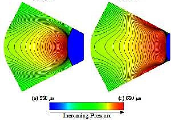
S. Lewin and B. Skews / JAFM, Vol. 14, No. 3, pp. 691-701, 2021.

image the central grouping of wavelets combine to       numerical results of one of the profiles that was
form a reflected shock, forming a Mach reflection       suggested, are shown in Fig. 3. This profile
with its associated shear layer.                        comprises a cylindrical arc placed in-between two
                                                        straight segments which are in a converging channel
                                                        made up of a pair of straight converging walls.
                                                        Initially, the shape of the shock wave resembles its
                                                        original profile. Compression waves emanating
                                                        behind the central region of the shock wave
                                                        propagate outwards along the shock front and
                                                        gradually coalesce. Immediately behind the shock
                                                        front, this occurs in the region where the cylindrical
                                                        and straight shock segments meet. As a result of the
                                                        extent to which the compressions steepen two
                                                        discontinuities in the form of kinks develop on the
                                                        shock front. As the propagation of the shock wave
                                                        progresses, two secondary shock waves eventually
   Fig. 1. Waves from a collapsing parabolic            emerge from the kinks. The profile of the resulting
                    surface.                            shock wave has effectively transitioned from what
                                                        was initially one curved shock wave, to a
                                                        configuration which is a symmetrical pair of Mach
                                                        reflections. The originally straight segments of the
                                                        shock wave represent the incident wave (i), the
                                                        cylindrical segment, the Mach stem (m), the
                                                        secondary shocks being the reflected waves (r), and
                                                        the kinks becoming, the triple points (t). The process
                                                        on either side of the symmetry plane is very similar
                                                        to that in Fig. 2.
                                                        All three of the above examples exhibit the same
                                                        physical phenomena. In order to explore them the
                                                        aim of the current investigation is to evaluate the
                                                        physical mechanisms responsible for the
                                                        development of reflected shocks on an initially
                                                        smooth and continuous shock front. It uses the
                                                        geometry of Fig. 3 to numerically investigate the
                                                        effect of the initial curvature radius, shock Mach
                                                        number and wall convergence angle on the
                                                        characteristic aspects of the shock propagation.

  Fig. 2. Modification of the profile of a shock
  wave on a curved surface due to influence of
             compression wavelets.

A third example arises from a suggestion in a
doctoral project dealing with the reflection of
cylindrical waves off a wedge (Gray 2014). This was         Fig. 3. Propagation of a compound shock wave.
part of a project dealing with the generation of
twodimensional shocks of arbitrary profile. The

                                                      692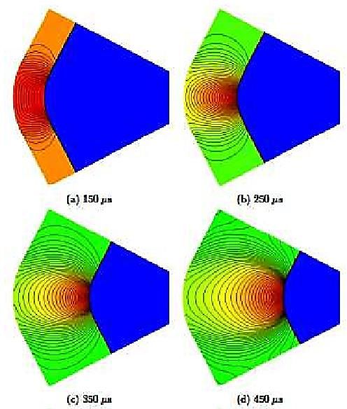
S. Lewin and B. Skews / JAFM, Vol. 14, No. 3, pp. 691-701, 2021.

       2.   NUMERICAL METHOD                                waves so was analysed using ANSYS Fluent’s
                                                            density-based solver. The speed at which the solution
The geometry of the computational domain was                converged, the memory requirements, as well as,
constructed with Autodesk Inventor, while ANSYS’            solution accuracy, were considered when specifying
Meshing and Fluent packages were used to generate           the various settings of the density-based solver. The
the mesh and solve the governing equations of the           ideal settings were those which resulted in the fastest
flow. Post-processing of the subsequent results was         solution convergence and required the least memory,
performed with Tecplot 360, and scripts were written        while simultaneously maintaining sufficient
in MATLAB to analyse and generate plots of the              accuracy. As a result, the explicit formulation of the
relevant data. This section details how the flow was        density-based solver was selected, with the Roe flux-
modeled and solved, and how the data required for           difference splitting (Roe-FDS) and Least Squares
analysis was obtained from the simulation.                  Cell Based Spatial Discretization schemes. The first
                                                            order implicit transient formulation was used, and the
2.1     Geometry                                            default Courant number (CFL) of 1 was retained.
                                                            These settings provided the optimal combination of
Due to the inherent symmetry of the geometry, it was
                                                            the afore-mentioned criteria.The size of the time step
only necessary to compute half the domain. A typical
                                                            was determined so that the shock would be
geometry is shown in Fig. 4. The left boundary was
                                                            sufficiently resolved . A time step of 1 x 10 −7 s was
defined by the profile of the initial shock wave,
                                                            found to be appropriate. The air inside the domain
which comprises a cylindrical arc and a straight
                                                            was modelled as an inviscid, ideal gas and initialized
segment. The straight segment is tangent to the
                                                            with atmospheric conditions (pressure of 101325 Pa
cylindrical segment so that the composite profile is
                                                            and temperature of 300 K). A shock wave was
smooth and continuous. It is also normal to the walls
                                                            simulated at the pressure inlet boundary by
of the propagation chamber. The length of the
                                                            specifying the conditions (static pressure, total
straight segment is thus determined by the length
                                                            pressure, total temperature) behind the shock wave
required to satisfy these conditions. The length of the
                                                            of the desired strength.
computational domain was truncated. The radius of
the cylindrical segment (referred to as the curvature
radius of the shock wave) and the angle at which the
chamber walls converge (referred to as the
convergence angle of the walls) was varied in the
different simulations.

                                                                       Fig. 5. Typical adapted mesh.

                                                            2.4 Extracting the Properties behind the
                                                            Shock Wave
                                                            In order to provide a physical description of the
      Fig. 4. Typical geometry of computational             shock propagation, it was necessary to obtain a
                        domain.                             temporal profile of the properties (specifically the
                                                            pressure) immediately behind the shock wave. This
2.2     Mesh                                                required the nodes in the interior of the domain that
                                                            represented the shock wave to be identified, so that
To ensure that the curved surface at the inlet of the       the corresponding properties at these nodes could be
domain, (Fig. 4), was accurately represented, the           exported into a suitable file for further analysis in
initial mesh was generated based on curvature, with         MATLAB. The post-processing suite available in
a curvature normal angle of 5 degrees, and a                ANSYS Fluent allows cells with constant values of a
maximum cell size of 2 mm. It was also necessary to         specified variable to be distinguished and grouped
utilize adaptive mesh refinement during the                 together as a distinct surface. Since the shock wave
simulations so that the shock wave was sufficiently         was captured during the simulations with adaptive
resolved. Cells were marked for either refining or          mesh refinement, it was possible to generate an
coarsening based on normalised gradients of                 isosurface representing the shock wave based on
pressure, density, temperature and velocity                 constant values of adaption space gradient. At each
magnitude. Cells were refined up to four times if the       instant in time for which an analysis was required,
normalised gradients were greater than 3% of the            the iso-value corresponding to the shock wave was
maximum and coarsened if the normalised gradients           selected interactively. As the iso-value was varied,
were less than 1.5% of the maximum. A typical               an instantaneous preview of the corresponding
adapted mesh is shown in Fig. 5.                            isosurface was created. Superimposing this preview
2.3     Solver                                              on a contour of the entire domain enabled an isovalue
                                                            that accurately captured the shock wave to be
The flow field under investigation contained shock          determined.

                                                          693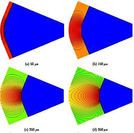
S. Lewin and B. Skews / JAFM, Vol. 14, No. 3, pp. 691-701, 2021.
Figure 6 demonstrates an example preview for one of comprising a cylindrical and straight segment. It will
the numerical simulations that was carried out. A be shown that during the course of the shock
preview of the surface corresponding to an isovalue propagation, the initially cylindrical shock segment
of 0.05 is shown in Fig. 6a. In Fig. 6b, this is is distorted, and hence, does not remain cylindrical.
superimposed on a pressure contour of the domain, Thus, from here on, this portion of the shock will be
which shows that this specific iso-value corresponds referred to as the curved shock segment. Similarly,
to the shock wave. Once the shock wave was the straight section becomes slightly distorted, even
successfully detected, the properties (particularly the though it appears straight in the figures presented.
static pressure and x and y coordinates) at the iso- This is similar to the situation described when
surface’s constituent nodes were exported to an dealing with Fig. 2; the incident wave is almost
ASCII file. This file was then imported into always treated as being plane up to the triple point
MATLAB for further processing. whereas it is actually influenced by compression
waves arising above this point. Thus in the current
Since the shock is detected based on the property study this segment will be identified as being
gradients across it, the iso-surface that is generated nominally straight. The implications that the
comprises two lines of nodes corresponding to the interaction of the curved and straight shock segments
fluid immediately behind and in front of the shock have on the phenomena that occur as the shock wave
wave. This is evident in the magnified view of the propagates in the channel is elucidated below.
iso-surface in Fig. 6b. In order to evaluate the
temporal variation of the properties of the fluid 3.1 General Description of Shock
immediately behind the shock wave, it is the Propagation
information at the corresponding line of nodes that is
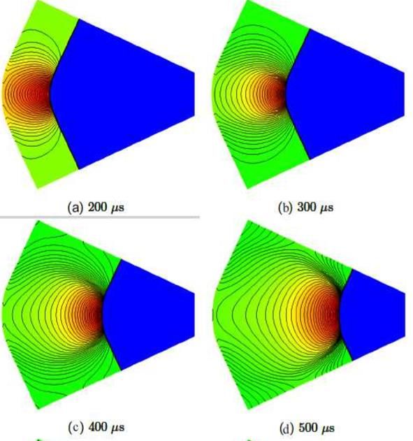
pertinent. As the fluid in front of the shock wave is The results for a typical case, in which the profile of
undisturbed, the pressure at the corresponding line of the initial shock wave transitioned into a
nodes is atmospheric. Using this fact, the data at the configuration resembling a symmetrical pair of
line of nodes representing the fluid immediately Mach reflections, is shown in Fig.7. Pressure
behind the shock wave was distinguished for use in contours show the flow at different times from when
the subsequent analyses, by examining whether the the shock was at the inlet. Initially, the shock front is
static pressure at these nodes was significantly smooth and continuous. As the shock wave
greater than atmospheric. converges, the curved segment straightens, and two
kinks develop on the shock front from which
reflected shocks emerge. As the shock continues
down the channel, the triple points of the Mach
reflection pair follow a divergent trajectory towards
the channel walls with increasing Mach stem length.
Eventually, the reflected shocks and triple points
meet the walls.
An evaluation of the pressure distribution
immediately behind the shock wave demonstrates
the mechanisms responsible for the phenomena
depicted in the figure. For any time during the
shock’s progression, the x and y coordinates of the
nodes representing the fluid immediately behind the
shock wave, and the corresponding values of static
pressure at those nodes, were obtained using the
method described above. At any node, the length of
the shock wave relative to the axis of symmetry was
determined with numerical integration using the
trapezoidal rule. It was then possible to plot the
temporal variation of the pressure distribution along
the length of the shock (Lshock). This is shown in
Fig. 6. Selection of a suitable iso-value. a:
Preview of the iso-surface corresponding to an It is evident that throughout the duration of the
isovalue of 0.05. b: Iso-surface superimposed on shock’s progression, the pressure distributions are
pressure contour. analogous. For each curve, the distribution from the
origin (which is at the axis of symmetry) to where the
end of the shock wave meets the channel wall is
obtained. The pressure is initially approximately
3. RESULTS
constant up until some point, where there is a drop in
the pressure. Beyond this region, the pressure is once
Simulations were run for a variety of independent again constant; until the weak compression waves
variables. The angle at which the channel walls reach the wall. Over time, the pressure increases
converged (Wall Convergence Angle), the initial before the pressure drop, while the pressure after it
Mach number and the initial curvature radius of the remains essentially constant. The increase in the
shock wave, ranged from 40 to 60 degrees, 1.1 to 1.4 slope of the curve at the pressure drop indicates that
and 130 to 190 mm, respectively. this drop becomes steeper with time.
The shock waves investigated have initial profiles
694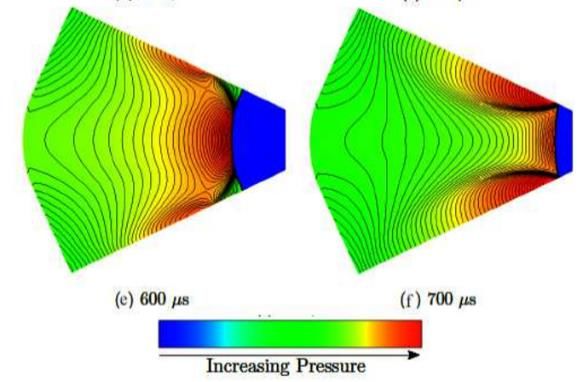
S. Lewin and B. Skews / JAFM, Vol. 14, No. 3, pp. 691-701, 2021.

                                                               Fig. 8. Temporal profile of pressure distribution
                                                               along the length of the curved shock wave (Wall
                                                                Convergence Angle: 50 Degrees; Initial Shock
                                                                    Mach Number: Mach 1.3; Initial Shock
                                                                         Curvature Radius: 160 mm).

                                                           3.2 Influence of Critical Parameters
                                                           The initial Mach number and initial curvature radius
                                                           of the shock wave, as well as the angle at which the
                                                           walls of the propagation channel converge, are
                                                           critical in determining how certain features of the
                                                           shock evolution are manifested. The influence of
                                                           these parameters on this process is discussed in the
                                                           following sections.
                                                           3.21       Trajectory of Pressure Variations
                                                           The pressure distribution behind the shock wave was
                                                           numerically differentiated using finite difference
Fig. 7. Pressure contours for the propagation of a         approximations. This gave the distribution of the
   curved shock wave in a converging channel               pressure gradients along the length of the shock
  (Wall Convergence Angle: 50 Degrees; Initial             wave. The temporal variation of the pressure gradient
 Shock Mach Number: Mach 1.3; Initial Shock                distribution is shown in Fig. 9 for the case portrayed
           Curvature Radius: 160 mm).                      in Fig. 7.

Fig. 8 for the case portrayed in Fig. 7.
It is well-established, that the strength of planar
shock waves is constant as they propagate. In
contrast, cylindrical shock waves increase in strength
as they converge. The pressure before the pressure
drop, at the pressure drop, and after the pres-sure
drop, corresponds to the pressure behind the curved
shock segment, the region where the curved and
straight shock segments meet, and the straight shock
segment, respectively. The result of the pressure
difference between these two regions manifests in
the phenomenon shown in Fig 7. To adjust for this
imbalance, compression waves, emanating from the
region behind the curved segment, propagate
outwards towards the region behind the straight                Fig. 9. Temporal profile of the pressure gradient
segment. The effect of these compressions is to                distribution along the length of the curved shock
distort the shape of the curved shock segment, (this             wave (Wall Convergence Angle: 50 Degrees;
effect is discussed further later). As the strength of          Initial Shock Mach Number: Mach 1.3; Initial
the curved shock segment increases as an imploding                    Shock Curvature Radius: 160 mm).
wave (and consequently, the pressured difference
steepens), the strength of the subsequent
                                                           At any time during the shock’s progression, the
compressions increases. As a result, they eventually
                                                           pressure gradient distribution is characterised by a
coalesce into a pair of shock waves on the originally
                                                           rapid rise, followed almost immediately by a sharp
smooth shock front resulting in the configuration of
                                                           dip in the pressure gradient. This occurs at some
a symmetrical pair of Mach reflections.
                                                           distance above the axis of symmetry (located at
                                                           Lshock equals zero in Fig. 9), and is a consequence

                                                         695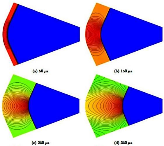
S. Lewin and B. Skews / JAFM, Vol. 14, No. 3, pp. 691-701, 2021.

of the pressure drop behind the shock wave (Fig. 8).        two sets; one representing the positions before the
The pressure drop behind the shock wave                     apparent focus, and the other representing the
corresponds to the region behind the intersection of        positions after focus.
the curved and nominally straight shock segments.
Therefore, here too, this rise and fall in the pressure     3.22 Prior to Focus
gradient, and in particular, the pressure gradient          The pressure gradient peak moves towards the plane
peak, must correspond to this intersection.                 of symmetry during this stage. Thus, even though
As the shock progresses through the channel, the dip        there is some distortion of the circular profile with
in the pressure gradient becomes steeper, and the           time, it still is an imploding curved wave
pressure gradient peak increases. This is in                strengthening as it propagates. The variation of the
accordance with the increase in the strength of the         y-coordinate of the pressure gradient peak with time,
curved shock segment with time. The pressure                and the time it takes for the shock wave to reach the
gradient peak increases rapidly until some time, after      focus was determined for all cases studied.
which the increase is relatively gradual. The               The variation of time to focus with the convergence
implications of this is discussed later.                    angle of the channel walls, with different initial
It is apparent that the position behind the shock wave,     curvature radii and Mach numbers, is given in Fig.
at which the pressure gradient peak occurs, varies          11. Although there is some scatter in these plots, the
over time. Since this position corresponds to the           dotted lines do capture the general trends. It is clear
region where the curved and nominally straight              that when the angle at which the channel walls
shock segments meet, it follows that by plotting the        converge is greater, the time to focus is longer. It is
temporal variation of its position, the trajectory of       also evident that when the initial curvature radius of
this region can be obtained. This is shown in Fig. 10,      the shock wave is larger, and the initial shock Mach
where the position of the pressure gradient peak,           number is lower, it takes longer for the shock to reach
represented by the filled circles, has been plotted on      the focus. This result is in accordance with what one
the shock wave at various times during its                  would expect, given that shock waves with larger
propagation.                                                curvature radii and lower Mach numbers are
                                                            synonymous with weaker, and hence, slower shocks.
                                                            angle. Left-hand plot: Mach number 1.1. Right-hand
                                                            plot; initial radius 160 mm.
                                                            Intuitively, the rate at which the shock focuses (and
                                                            consequently, the time to focus) is dependent on the
                                                            rate at which the shock increases in strength before
                                                            the focus. The Rate of Change (ROC) of the
                                                            maximum pressure gradient over time is a
                                                            convenient measure of the rate at which the shock
                                                            increases in strength, and hence, of the acceleration
                                                            of the shock wave. The rate at which the maximum
                                                            pressure gradient changes with time before the focus
                                                            is shown in Fig. 12 for the propagation of shock
Fig. 10. Progression of a curved shock wave with            waves, with different initial Mach numbers and
an initial Mach number and curvature radius of              curvature radii, in channels with varying wall
 1.3 and 160 mm (Wall Convergence Angle: 50                 convergence angles. In all cases, at some time after
                    Degrees).                               the start of the shock propagation, there is an
                                                            exponential growth in the rate at which the maximum
                                                            pressure gradient increases, and hence, in the
At first, the pressure gradient peak moves towards
                                                            acceleration of the shock wave. Therefore, the earlier
the axis of symmetry (the x-axis in the figure), and
                                                            this increase occurs, the sooner the shock wave
then after reaching some minimum distance above it,
                                                            moves towards the focus. It is evident, that shock
it diverges away from the symmetry axis. Therefore,
                                                            waves experience this exponential increase earlier,
the propagation of the curved segment can be
                                                            and therefore, arrive at the focus sooner, when the
inferred from the trajectory of the pressure gradient
                                                            initial Mach number is higher, the initial curvature
peak. This conforms with what is known regarding
                                                            radius is smaller, and the wall convergence angle of
the propagation of cylindrical shock waves; Initially,
                                                            the propagation channel is lower. This corresponds
the curved segment (which was initially cylindrical)
                                                            with the results presented in Fig. 11. Finally, the
converges towards its focus, shown as a star, and
                                                            slope of the curves in Fig. 12a is steeper when the
then expands as it moves away from the focus. The
                                                            initial shock Mach number is higher. Therefore, the
minimum height that the pressure gradient peak
                                                            shock wave accelerates at a greater rate when the
reaches, before diverging away from the symmetry
                                                            initial Mach number is higher. In contrast, the slopes
axis, must then be the apparent focus. The influence
                                                            of the curves in Fig. 12b and c are almost
of the critical parameters on the trajectory of the
                                                            indistinguishable. This implies that the initial Mach
pressure gradient peak (and by inference, the
                                                            number of the shock wave has a more significant
intersection of the curved and nominally straight
                                                            influence on the rate at which the shock wave
shock segments), as the shock wave moves towards
                                                            accelerates and reaches the focus than the initial
and away from the focus, is discussed below. The
                                                            curvature radius and wall convergence angle.
coordinates corresponding to the position of the
pressure gradient peak over time were divided into

                                                          696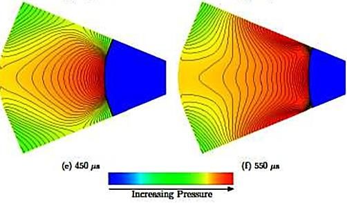
S. Lewin and B. Skews / JAFM, Vol. 14, No. 3, pp. 691-701, 2021.

                          Fig. 11. Variation of time to focus with wall convergence.

                           Fig. 12. Rate of change of maximum pressure gradient.

3.23 Post focus                                             the shock wave, and the line on the right (with the
                                                            positive slope) corresponds to the trajectory of the
For the case shown in Fig. 7 and 10 the apparent            peaks away from the focus. The pressure gradient
focus is at approximately 209µs. Between 150 and            peak behind the shock wave occurs in the region
250 µs the curved wave has become increasingly              where the curved and nominally straight shock
distorted and considerably less cylindrical and no          segments meet, and the subsequent drop in the
longer propagates as an imploding shock.                    pressure gradient becomes steeper with time (Fig. 9).
At this time, the reflected shocks have not yet             As the drop in the pressure gradient becomes steeper,
developed. The dashed line on the left, plotted in Fig.     a discontinuity in the pressure behind the shock
10, represents the initial propagation toward focus of      wave, in this region, begins to develop, as the

                                                          697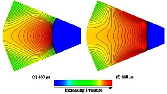
S. Lewin and B. Skews / JAFM, Vol. 14, No. 3, pp. 691-701, 2021.

compression waves start to bunch together. This              trajectory angle with the initial curvature radius and
bunching together means less of the compression              wall convergence angle, for shock waves with
waves propagating ahead of the developing                    different initial Mach numbers, is given in Fig. 13.
discontinuity affect the shock profile and therefore         The higher the initial Mach number, the steeper the
have less influence on its shape. Thus as the shock          trajectory angle of the triple points. It is also steeper
moves from 250µs to 600µs it becomes straighter              when the initial curvature radius of is larger, and the
aproaching the surface, as the curved portions               convergence angle of the channel walls is lower.
contain the compressions eventually contributing to          Additionally, since the slopes of the different lines in
the reflected shock. This is analogous to the example        the plots are almost identical, it can be inferred, that
in Fig. 2 where the more remote compressions do not          the rate at which the trajectory angle varies with the
contribute to forming the reflected shock. Since,            initial curvature radius and wall convergence angle
discontinuities in the thermodynamic properties of a         is essentially independent of the shock Mach
fluid are characteristic of shock waves, it follows that     number.
the reflected shocks eventually emerge in this
bunched up region. Therefore, the upward sloping             3.3 Transition
curve on the right in Fig. 10, not only describes the        In Fig. 14, the influence of the convergence angle of
trajectory of this developing discontinuity region,          the channel walls, the initial shock Mach number,
and the development of a kink in the shock, away             and the curvature radius, on the temporal variation of
from the focus, it also represents the development of        the pressure gradient distribution behind the shock
the trajectory of the triple points of the eventual          wave is shown. The position behind the shock wave,
Mach reflection pair. Thus, the slope of this line           where the pressure gradient peak and the subsequent
tends to that of the triple point trajectory.                drop in pressure gradient occurs, corresponds to
                                                             where the reflected shocks eventually emerge. Thus,
                                                             at any given time, the slope of the pressure gradient
                                                             distribution at the drop is an indication of the degree
                                                             to which the reflected shock has developed.
                                                             Furthermore, the rate at which this slope becomes
                                                             steeper over time indicates the rate at which the
                                                             reflected shocks develop. Therefore, a comparison,
                                                             at corresponding times, of the slope of the curves of
                                                             the various cases in each plot allows the influence of
                                                             the critical parameters on the rate at which the
                                                             reflected shocks develop to be deduced.
                                                             Initially, the slope at the pressure gradient drop is
                                                             steeper when the wall convergence angle is lower
                                                             (Fig. 14a). This is because shock waves propagating
                                                             in channels with lower wall angles converge to the
                                                             focus at a faster rate. However, at later times during
                                                             the shock’s progression, the slope at the pressure
                                                             gradient drop is steeper when the wall convergence
                                                             angle is higher. The reason for this is that the strength
                                                             of the shock wave (and accordingly, the magnitude
                                                             of the maximum pressure gradient) when it arrives at
                                                             the focus, is greater when the wall convergence angle
                                                             is higher. Since the increase in the strength of the
                                                             shock wave, as it moves away from the focus is
                                                             gradual relative to the increase in its strength as it
                                                             focuses, shock waves propagating in channels with
                                                             higher wall convergence angles exceed in strength
                                                             shock waves in channels with lower wall angles.
                                                             Therefore, the rate at which the reflected shocks
                                                             develop is greater when the wall convergence angle
                                                             is higher. Hence, the reflected shocks emerge on the
                                                             shock front earlier than when the wall angle is lower.
                                                             In Fig. 14b and Fig. 14c, it is evident that when the
                                                             initial Mach number of the shock wave is higher, and
                                                             the curvature radius is smaller, the slope at the
                                                             pressure gradient drop becomes steeper at a greater
 Fig. 13. Variation of the trajectory angle. Top:
                                                             rate. This is especially apparent at 200µs in Fig. 14b,
  variation with initial curvature radius, wall
                                                             and at 300µs in Fig. 14c. From this it can be inferred,
  angle 50◦. Bottom: variation with wall angle,
                                                             that a reflected shock emerges on the shock front
           curvature radius 130 mm.
                                                             sooner when the initial Mach number of the shock
                                                             wave is higher, and the curvature radius is smaller.
An approximate estimate of the trajectory is obtained        In order to gain insight into the effect of the critical
by a linear fit to the data. The variation of the            parameters on whether the profile of the shock wave

                                                           698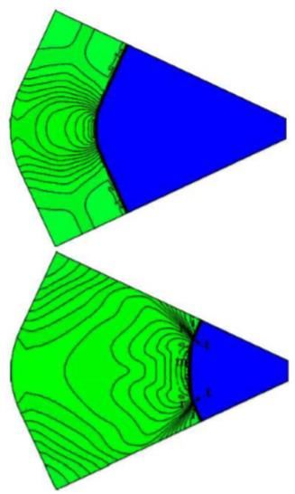
S. Lewin and B. Skews / JAFM, Vol. 14, No. 3, pp. 691-701, 2021.

 Fig. 14. Temporal variation of the pressure gradient distribution behind the shock wave for different
                       wall angles, shock Mach numbers, and curvature radii.

transitions within the duration of its propagation, the
temporal evolution of the shock profile was
evaluated. A shock wave was considered to have
transitioned, if reflected shocks of comparable
strength to the primary shock front had emerged
before the region where the curved and nominally
straight shock segments meet (representative of the
locus of the eventual triple points), intersected the
walls of the propagation channel.
In Figs. 15 to 17, pressure contours depicting the
progression of the shock wave for different cases are
shown, to illustrate how the various cases were
assessed.
In Fig. 15, the shock wave, at 550µs, is just prior to
the instant the triple points meet the walls of the
propagation channel (Fig. 15f). Although the
compressions behind the shock wave have begun to
coalesce into the start of reflected shocks, this has not
occurred to the same extent as the compression of the
primary shock wave. Therefore, in this case, it was
considered that the shock wave had not yet
transitioned before its triple points interacted with
the channel walls. In contrast, in Fig. 16, even though
the reflected shocks emerge only just before the triple
points intersect the channel walls (Fig. 16f), the
compressions have coalesced to a similar extent as                   Fig. 15. Propagation of a shock wave in a
those defining the primary shock wave. Thus, for this              channel converging at 45 degrees. The shock
case, the shock wave was determined to have                       wave has an initial Mach number and curvature
                                                                             radius of 1.4 and 190 mm.

                                                            699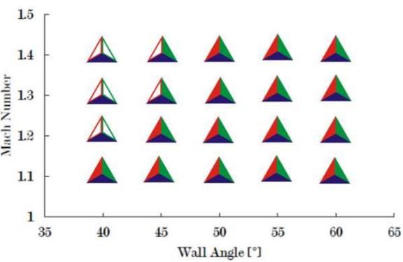
S. Lewin and B. Skews / JAFM, Vol. 14, No. 3, pp. 691-701, 2021.

The transition classification of the various cases that     angle of the propagation channel is lower. This
were evaluated is presented in Fig. 18, for shock           agrees with the earlier comments which showed that
waves with initial curvature radii of 130 mm                for the corresponding conditions, the trajectory angle
(coloured blue), 160 mm (coloured green) and 190            of the triple points is greater. As was discussed there,
mm (coloured red). For each case, if the shock wave         when the trajectory angle of the triple points is
was determined to have transitioned, it was                 greater, the triple points meet the walls of the channel
represented by a filled triangle in the figure. In the      earlier. Another aspect to consider is that when the
figure each distinct case can be identified by the          initial curvature radius of the shock wave is larger
initial Mach number of the shock wave (y-axis) and          and the wall convergence angle is lower, it takes
the wall convergence angle of the propagation               longer for reflected shocks to develop.
channel (x-axis).                                           Consequently, for these conditions, the likelihood of
                                                            transition occurring is reduced even further.
When the initial curvature radius was 130 mm,
transition occurs for all wall angles and Mach
numbers tested. However, where the initial curvature
radius of the shock wave was 160 mm, when the
convergence angle of the propagation channel was
less than 45 degrees, and the shock Mach numbers
was greater than 1.2, transition did not occur.
Similarly, when the initial curvature radius is 190
mm, for wall angles less than 50 degrees and shock
Mach numbers greater than 1.2, and for wall angles
less than 45 degrees and shock Mach number greater
than 1.1, transition does not occur.

                                                                   Fig. 17. Propagation of a shock wave in a
                                                                 channel converging at 55 degrees. The shock
                                                                wave has an initial Mach number and curvature
                                                                           radius of 1.4 and 190 mm.

   Fig. 16. Propagation of a shock wave in a                        1.   CONCLUSION
 channel converging at 50 degrees. The shock
wave has an initial Mach number and curvature               The propagation in a converging channel, of shock
           radius of 1.4 and 190 mm.                        waves with initial profiles comprising a cylindrical
                                                            arc in-between two straight segments was evaluated
Although qualitative, the results of this evaluation do     through various numerical simulations. The
provide an indication of the influence of the critical      characteristic features of the change in the shock
parameters on transition. The likelihood of transition      profile over the duration of its propagation were
occurring during the shock’s progression decreases          evaluated. In general, the curved segment of the
when the initial Mach number and curvature radius           shock front is distorted and flattened as the shock
of the shock wave is higher, and the convergence            wave converges to its focus. As the shock propagates
                                                            away from the focus, two kinks develop on the shock

                                                          700
S. Lewin and B. Skews / JAFM, Vol. 14, No. 3, pp. 691-701, 2021.
front, from which reflected shocks emerge. This angle of the triple points is greater. As a result, the
results in a configuration resembling a symmetrical triple points intersect the walls of the channel earlier.
pair of Mach reflections. The triple points of the The likelihood of reflected shocks developing within
Machreflection pair follow a divergent trajectory, the duration of the shock’s propagation in the
away from the axis of symmetry. channel is thus reduced. This effect is further
exacerbated in cases where the wall convergence
The physical mechanism responsible for the angle is lower and the initial curvature radius is
development of the reflected shocks was elucidated larger since under these conditions, the rate at which
by an evaluation of the temporal variation of the the reflected shocks are formed is slower and
pressure distribution behind the shock wave. This therefore, the triple points intersect the channel walls
showed that the pressure behind the curved shock before the reflected shocks can completely develop.
segment increases over time, while the pressure
behind the straight segments are essentially constant. The first author gratefully acknowledges the bursary
Compressions propagate along the shock front support of the SITA Air Transport Community
towards the straight shock segments to correct this Foundation.
pressure imbalance. As the pressure behind the
curved shock segment increases, subsequent REFERENCES
compressions propagate at a greater velocity and
eventually, they coalesce into reflected shocks. As a
Grö nig, H. (1986). Shock wave focusing phenomena.
result of the increase in the pressure behind the
In D. Bershader and R. Hanson (Eds.),
curved shock segment with time, this portion of the
Proceedings of the fifteenth international
shock front is distorted and flattened.
symposium on shock waves and shock tubes,
Berkeley, CA, pp. 43–56. Stanford University
Press.
Gray, B. (2014). On the propagation and reflection
of curved shock waves. Ph. D. thesis,
University of the Witwatersrand,
Johannesburg, South Africa.
Payne, R. (1957). Numerical method for a
converging cylindrical shock. Journal of Fluid
Mechanics 2(2), 185–200.
Perry, R. and A. Kantrowitz (1951). The production
and stability of converging shock waves.
Journal of Applied Physics 22(7), 878–886.
Fig. 18. Transition classification. Closed symbols
represent development of Mach reflection. Initial Skews, B. and H. Kleine (2009). Unsteady flow
curvature radius: Blue 130 mm; Green 160 mm: diagnostics using weak perturbationsr.
Red 190 mm. Experiments in Fluids 46, 65–76.
Skews, B., I. Komljenovic and T. Sprich (2008).
The initial Mach number and curvature radius of the Generation of unsteady flows from rapidly
shock wave, as well as the wall angle of the moving boundaries. In J. P. Meyer (Ed.), 6th
converging channel was varied. It was found that: • International Conference on Heat Transfer,
When the wall convergence angle is lower, the initial Fluid Dynamics and Thermodynamics,
curvature radius is smaller and the shock Mach Pretoria. HEFAT.
number is higher, the shock wave moves towards Sod, G. (1977). Numerical study of a converging
focus sooner. The reason for this was that the rate at cylindrical shock. Journal of Fluid Mechanics
which the shock increases in strength, and hence 83(4), 785–7946.
accelerates, is greater. • When the wall convergence
angle is lower, the initial curvature radius is larger,
and the shock Mach number is higher, the trajectory
701You can also read