Robust Fuzzy MIMO Bang-Bang Controller for two Links Robot Manipulators
←
→
Page content transcription
If your browser does not render page correctly, please read the page content below
Australian Journal of Basic and Applied Sciences, 5(12): 2071-2083, 2011
ISSN 1991-8178

     Robust Fuzzy MIMO Bang-Bang Controller for two Links Robot Manipulators

                              Marwan A., Farrukh Nagi, KSM Sahari, Hanim S.

          Universiti Tenaga Nasional, Jalan Ikram-Uniten, Kajang, 43000, Selangor, Malaysia.

    Abstract: In this paper a new fuzzy controller for multi-input-multi-output (MIMO) systems has been
    proposed. The new MIMO self-tuning robust controller is called as Fuzzy Bang-Bang Controller
    (FBBC) and is used for rigid-type robot which has two links manipulators. The controller operation is
    demonstrated by simulation of manipulators movement from any initial position to up and downward
    positions. The comparison between the proposed controller and Slide Mode Controller (SMC) is
    carried out for to tracking performance ability. The comparison is based on: the speed of convergences,
    maximum payload, amplitude and frequency. It was concluded that based on the tables and the
    simulation results proposed controller is better than slide mode controller (SMC) in handle big load,
    amplitude and frequency.

    Keywords: Bang-Bang, robotic manipulators, self-tuning controller, MIMO systems control.

                                                 INTRODUCTION

     Dynamics of rigid robot manipulators are highly nonlinear and contain uncertain elements such as friction.
Many efforts have been made in developing control schemes to achieve the precise control of robot
manipulators (Feng Lin, 2007; Weibing Gao and James C. Hung, 1993; Elbrous, M.J, et al., 2002; Mahdi, S.A,
et al., 2009; .-A.,Saad, 1992; Shinya, A., 2009). Among available options, fuzzy control has a great potential
since it is able to compensate for the uncertain nonlinear dynamics using the programming capability of human
control behavior. In control theory, a bang–bang on–off controller, switches abruptly between two states. They
are often used to control a plant that accepts a binary input, for example a furnace that is either completely on or
completely off. Most common residential thermostats are bang–bang controllers. The Heaviside step function in
its discrete form is an example of a bang–bang control signal. Due to the discontinuous control signal, systems
that include bang–bang controllers are variable structure systems, and bang–bang controllers are thus variable
structure controllers. Artificial intelligence technique such as fuzzy logic has provided the means to develop
flexible fuzzy bang-bang controller. One of the earliest fuzzy bang-bang controllers (FBBC) was developed by
Chiang and Jang (Richard, Y., et al., 1994). It made debut in Cassini spacecraft’s deep space exploration
project.
     Nowadays, digital processors are readily available for the industrial implementation of the fuzzy
controllers. The fuzzy controllers are flexible, simple to build and provide robustness to the bang-bang
controller. As the application of fuzzy controller widens, more complex systems are attempted and solutions
have expanded to neural networks. As a result, fuzzy neural networks bang-bang controllers have gained the
attention of researchers. Grantham and Mesbah (Grantham K.H., 1996) have demonstrated how a fuzzy bang-
bang system can be converted to fuzzy neural network. The fuzzy set parameters, which are based on human
logic rules, cannot be trained to meet the specific requirement. Neural networks, on the other hand are provided
with learning abilities. The purpose of modifying the fuzzy controller to fuzzy neural network controller is to
train the controller to meet the desired response.
     The idea of fuzzy controller is not new. (A. Kendal, 1991) and Mamdani (W.J.M. Kichert and E.H.
Mamdani, 1978) were first to point out that with mean of maxima (MOM) defuzzification, the fuzzy controller
is identical to a multilevel relay. Application of the fuzzy relay in power control was first presented by Panda
and Mishra (G. Panda, R.R. Mishra, 2000). Hard limiter was used in this work to convert the defuzzified output
to two-level control. New controllers are not acceptable to control community, unless their stability is proven
with the existing stability techniques. In case of fuzzy controllers, the heuristic approach of fuzzy rules results in
partitioning of decisions space (phase plane) into two semi-planes by means of a sliding (switching) line.
Similarity between fuzzy bang-bang controller and sliding mode controller (SMC) can be used to redefine the
diagonal from of fuzzy logic controller in terms of an SMC, with boundary limits, to verify the stability of the
proposed bang-bang controller (Chung-Chun K. and Chia-Chang L. 1994; Rainer Palm, et al., 1997). SMC is a
robust control method (Slotine, J.J.E and Weiping Li, 1991) and its stability is proven with lyapunov’s direct
method. So in lieu of SMC, the fuzzy bang-bang control stability can be easily established.
     In optimal control engineering, the optimal time problem is to find the best possible control technique to
transfer the state of the system from a given initial stat to a specified final state in the shortest possible time. The
minimum time control is highly desirable for bang-bang controller design, especially for satellite attitude
control. The Pontrygin’s minimum Principle (PMP) has been extensively used to design time optimal control
Corresponding Author: Marwan A., Universiti Tenaga Nasional, Jalan IKRAM-UNITEN, Kajang, 43000, Selangor,
                      Malaysia.
                      E-mail: marusm@live.com.
                                                         2071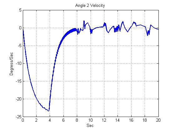
Aust. J. Basic & Appl. Sci., 5(12): 2071-2083, 2011
(Michael Athans and Peter L. Palb, 1966). PMP states that Hamiltonain function described by states and costate
trajectories together with control effort in minimum time, when solved, yield the optimal state trajectory
corresponding to optimal control effort. It is not a surprise that the sliding line of SMC and state trajectory
solution of PMP optimal control have almost similar control laws as shown by Kulczycki (Piotr Kulczycki,
2000), thus establishing the fact that fuzzy bang-bang control is indeed a robust control system.
Fuzzy bang-bang Controller has been successfully applied in various areas for nearly two decades. Some of
these are in spacecraft satellite attitude control systems (Thongchet S. and Kuntanapreeda, S., 2001) the servo
systems VIA (S.Y. Chang, et al., 1995) Control of Water Tank System (K. Tanaka, M. Sugeno, 1992) in the
reduction of harmonic current pollution (B. Mazari and F. Mefri, 2005) crane hosting and lowering operation (S.
Yasunobu, S. Miyamoto, 1985) the elevator control (F. Fujitec, 1988) and in process control valves operation
(R. Ushiyama and H. Walden, 1991). FBBC has become a popular tool after these successful applications.
Recently, many analysis results and design methodologies of fuzzy control have been reported. However, most
of these reported research only focused on single-input-single-output (SISO) systems. Multi-input-multi-output
(MIMO) fuzzy controllers are desirable in many situations.
In this paper the proposed FBBC consists of many sets of linguistic rules. Each set of linguistic rules is
designed as a suction controller. Its shows that there is a switching manifold in the MLFLC. The consequent
part of the fuzzy rules has only three linguistic values, while the premise parts are freely chosen. It is structurally
simple due to three membership functions in its fuzzy output set and rule matrix. An important feature of
FBBRC is its flexibility and its optimal time response, which is independent of initial conditions. This paper is
organized as follows. In section 2, the MLFBBC is reviewed and the membership functions for a complement
type of a control structure for MIMO systems are defined. In section 3, a two- link manipulators robot system is
studied to demonstrate the FBBC. Simulation results of the two controllers are compared and analyzed in
section 4. Finally, conclusions are presented in section 6.
The membership functions for a complement type of a control structure for MIMO systems:
The FBBC is reviewed in this section. In addition, a special type of membership functions, the complement
type, is defined. The ranges of state input and output variables it is necessary for any fuzzy controller, which are
considered to be a reasonable representation of situations that controller may face and yield to stability and
optimality conditions. Figure 6 shows the structure of FBBC with the self-tuning optimization scheme which
described below.
Linguistic Description:
The inputs and output parameters, as well as the partitions and spread of the controller membership
functions are initially selected to match the dynamic response of a manipulators robotics system. The inputs xi Є
Xi, where Xi is the universe of discourse of the four inputs, i =1, 2, 3, 4. For input variable, x1 =, “error angle for
link 1”, x2 =,” error angle for link 2”, the universe of discourse, X1,2 = [-20, 20] deg., which represents the range
of perturbation angle about the zero reference. Index k is assigned to tally the input membership functions. For
input variable x3 = “error angle rate for link 1”, and x4 = “error angle rate for link 2”, the universe of discourse
X3, 4 = [-10, 10] deg. /sec. The output universe of discourse y= [-200, +200] represents the bang-bang output.
~
The set Aik is the membership function of antecedent part defines as
~ ~ ~ ~
Aik = [ Ai1 =LN, Ai2 = Z, Ai3 =LP] (1)
~j ~j ~j ~j k
Similar values are selected for inputs x1, A2 A3 A4 A1 . The set B which denotes the
2, 3, 4
membership function values for outputs variable y1, 2 are defined as
B1k = [ B11 =J2, B12 =Z, B32 =J1]
B 2k = [ B 12 =J2, B2 =Z, B32 =J1]
2
J1,2, Z1,2 and J1,2 are on/off- firing command for the robot manipulators link1 and link2, respectively.
Fuzzy Rules:
The Fuzzy bang-bang action is a nonlinear control technique that is based on heuristic human logic rules.
An initial setting of inference rules is conducted first. The initial value of ai j , is so set that the domain of input xj
is divided equally. The initial value of width bi j is set to allow overlaps of membership functions. These rules
are based on four inputs variables, each with three values, thus there are at most (N=34= 81 regular rule
partitions) are defined as (LN, Z, LP). Where LN = Large Negative, Z = Zero, LP = Large Positive. The tuning
rules-partitions are heuristically chosen to reset the links smoothly over the universe of discourse. In other
2072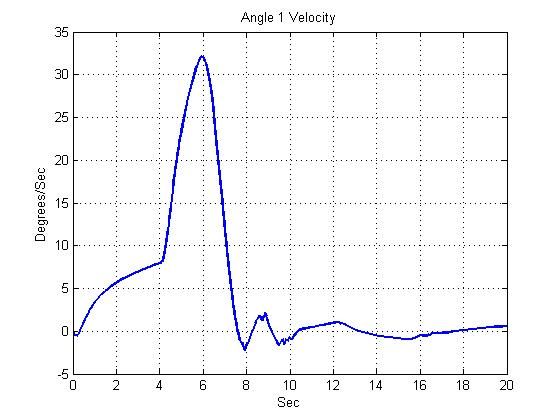
Aust. J.
J Basic & Appl. Sci., 5(12): 2071-2083, 2011
words, thee input are exp pressed by x1, x2,…., xm ,, and the outp put is expresseed by y, the innference rule of
simplified fuzzy reasoninng [24] can be expressed by thhe following.
Rule i:
HEN y is wi (i= 1,... , n)
If x, iss A;, and... andd xm , is Ai, TH
The fuuzzy rules can be b illustrated as
a a representattion of the mattrix of 81 rows and 3 columns (the number of
membershiip function is depicted.
d Figu
ure 1 ((a) & (b))) respectively show the surfface for the rulles of the FBB
BC
before andd after tuning.
(
(a) (b)
Fig. 1: view
wer surface forr the rules of th
he FBBC: (a) before
b tuning (bb) after tuning.
The sy
ymmetry of thee rules matrix is expected ass it arises from
m the symmetryy of the system
m dynamics. Thhe
decomposiition of the jth rule
r from the FBBC‘s
F inputs to the output iss given by
2
(y)B ( xi ) A k (2)
j i 1 i, j
Wheree j = 1, 2, 3, 4,,….n. , is the in
ndex of n matcching rules, whhich are applicaable from inferrences of inputts.
Conventionnal Fuzzy FB BBC uses the standard decoomposition tecchnique (Richaard, Y., et al., 1994; W.J.M M.
Kichert andd E.H. Mamdaani, 1978; S.Y. Chang, et al., 1995).
Fuzzy Set Membership
M F
Functions:
The in nput variabless and values assigned to fuuzzy set mem mbership functtions are show wn in Figure 3.
Triangular shape membeership function ns are used inn this work. Thhese membersship functions are sensitive to
small channges that occurr in the vicinityy of their centeers. A small chhange across thhe central mem
mbership functioon
A 12 , locatted at the origgin, can producce abrupt swittching of contrrol command u between thee + ve and – ve
halves of the
t universe off discourse, ressulting in chatttering. The oveerlapping of the central mem
mbership functioon
membershiip functions A 13 with the neigghboring mem mbership functioons A 11 and A 13 reduce the sensitivity
s of thhe
bang-bang control action n. The membeership functionn Ai of the anntecedent part is expressed by an isoscelles
triangle shoown in Figure 2.
Wheree i is a memmbership value of the anteceddent part.
Fig. 2: Meembership Funcction of Anteceedent Part.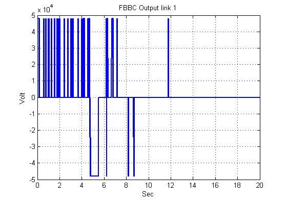
Aust. J. Basic & Appl. Sci., 5(12): 2071-2083, 2011
Triangular membership functions in Figure 2 are based on mathematical characteristics given in Table 1. In
Table 1 the bi and ai are the tuning parameters for range and central location of membership functions
respectively and shown in Figure 3. Smooth transition between the adjacent membership functions is achieved
with higher percentage of overlap, which is commonly set to 50%.
Table 1 Mathematical Characterization of Triangular Membership Functions
Linguistic value Triangular Membership functions
1 x bi
Aik 1
1
Ai ( x ) 2xa i
1 bi x a i
bi
2 x ai
Ai2 1 ai x 0
bi, j
A i2 ( x )
1 2 x ai
0 x ai
bi
2 x ai
Ai3 1 a i x bi
A i3 ( x ) bi
1 x b i
The input- output data (xi ,..., xm , y r ) is inputted. Fuzzy reasoning is performed for the input data (x1,..., xm)
by using Equations 4 and 6. The membership value i of each inference rule and the output of fuzzy reasoning
y are derived.
i Ai11 (x1) Ai22 (x2 ) .... Aikm (xm ) (5)
n
i wi
(6)
i 1
y n
i
i 1
Fig. 3: Un-tuned membership functions of input x 1, 2 = ‘error angle‘, x 3, 4= ‘error angle rate’ for FBBC.
2074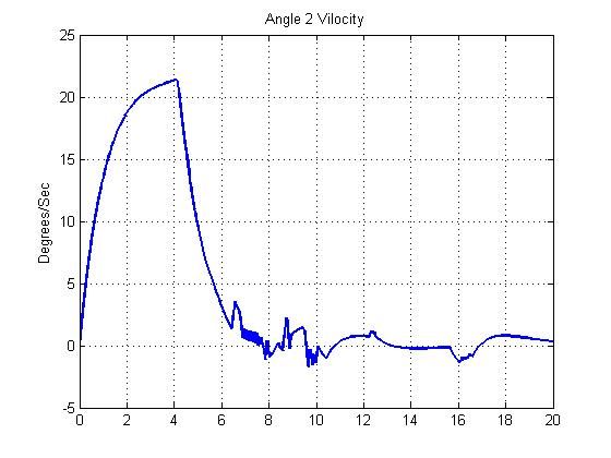
Aust. J. Basic & Appl. Sci., 5(12): 2071-2083, 2011
Tuning of a real number wi of the consequent part is performed offline by substituting the output of fuzzy
reasoning y, membership value i , and output data y r
into Equation 16. Tuning of the center value ai j and the
width bi j of membership functions of the antecedent part is conducted by substituting the changed real number
wi of the consequent part in procedure of, the output of fuzzy reasoning y, membership value i and output
r
data y into Equations 7 and 8.
Ka i 2 (7)
ai j (t 1) ai j (t ) ( y y r ) ( wi (t ) y ) sgn( x j - ai j (t ))
n bi j (t ) Ai j ( x j )
i
i 1
Kb i 1 Ai j ( x j ) 1 (8)
bi j (t 1) bi j (t ) n
( y y r ) ( wi (t ) y )
Ai j ( x j ) bi j (t )
i
i 1
Kw i
wi (t 1) wi (t ) n
(y yr )
i
i 1
The inference error D(t) is calculated from Equation 9, and [Step 3] to [Step 6] are repeated until its change
D(t)-D(t-1) is less than a threshold value.
1 (9)
D (t ) ( y (t ) y r ) 2
2
The membership functions of input x 1, 2 = ‘error angle‘, x 3, 4= ‘error angle rate’ for FBBC after tuning are
showing in Figure 4.
Fig. 4: The tuned membership functions of input x 1, 2 = ‘error angle‘, x 3, 4= ‘error angle rate’for FBBC.
Structure of the fuzzy logic controller for bang-off-bang output (fuzzy bang-off-bang):
The structure of the fuzzy logic controller for bang-off-bang output is similar to that in the largest value of
the domain with maximal membership degree except for the addition of one output fuzzy set. The span for the
fuzzy set off is set to zero. The output is 200,-200 or 0 similar to bang-off-bang the Largest of Maximum
2075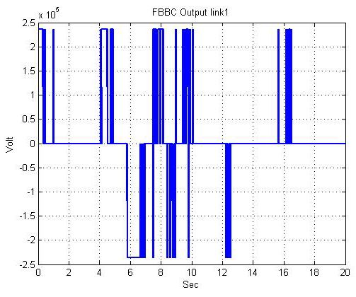
Aust. J. Basic & Appl. Sci., 5(12): 2071-2083, 2011
(LOM) Aggregation controller output. The outputs membership functions shown in Figure 5(a). Perturbation of
the links from the zero reference acts on the output membership functions according to the rule matrix. The
Bang-Bang firing action J of output membership functions is shown in Figure 5(b).
Fig. 5 (a): FBBRC outputs y1, 2 membership functions. (b) FBBC two level Bang-Bang y1, 2 crisp outputs.
In control theory, gain scheduling is an approach to control of non-linear systems that uses a family of
linear controllers, each of which provides satisfactory control for a different operating point of the system. The
linearization of outputs FBBC membership functions gains simply have been selected as presented in the
equations 10 and 11 respectively to control the robot manipulators movements with different payloads..
G 1 180 mL *10 (10)
G 2 80 m L * 8 (11)
Where m L is the payload value
Fig. 6: The structure of FBBC with the self-tuning optimization scheme in Matlab/Simulink environment.
2076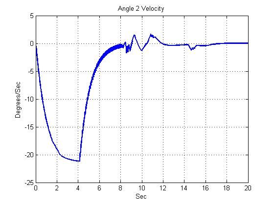
Aust. J. Basic & Appl. Sci., 5(12): 2071-2083, 2011
Case study: A two-link rigid-type robot manipulators:
In this section, we illustrate the performance of the FBBC by simulation of a two-joint rigid- type rigid
robot. For the following robot no longer assume that the link masses are concentrated at the centers of masses.
Hence, each link has a moment of inertia. All one, assume that there are frictions in the joints. The mechanical
model of a robot manipulator is shown in Figure 7. Table 2 shows the parameters of the tow-link SCARA-type
robot (Feng Lin, 2007).
y
mL
J2
q2
J1
q1
x
Fig. 7: Tow-link rigid-type robot manipulator.
Table 2: Parameters of the tow-link rigid-type robot (Feng Lin, 2007) .
Parameters link 1 Parameters link 2
m1 13.86oz m 2 3.33oz
J 1 62.39ozin 2
J 2 110.70ozin 2
l1 8in l 2 6in
r1 4.12in r2 3.22in
b1 20ozins b2 50ozins
m L [5,100]oz
The system simulated with the goal of controlling the manipulator movement from any initial position to
the up or downward position with different payload possible. That is1 90 or 90 , 2 90 or 90 . The
dynamic equation of the rigid robot manipulator as taken from reference [1] defines as below.
M 11 M 12 q1 V1 U 1 W1 1
M (11)
21 M 22 q2 V 2 U 2 W 2 2
Where
q is the generalized coordinate vector
is the generalized force vector
M (q) is the inertia matrix
V (q, q ) is the Coriolis/centripetal vector
W (q) is the gravity vector
U (q) is the friction vector
The elements in the above equation have been calculated as follows.
q
q 1 1 , 1
q2 2 2
2077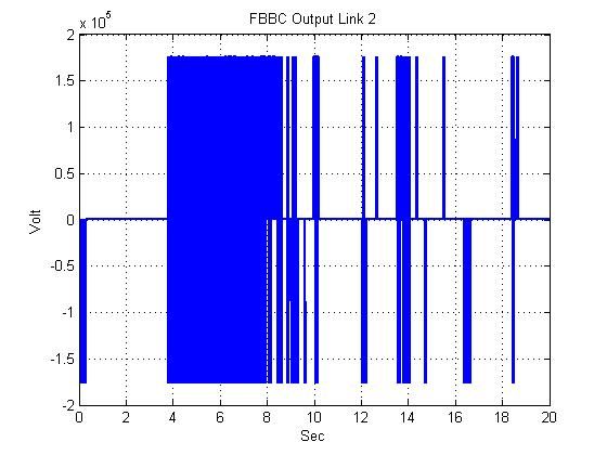
Aust. J. Basic & Appl. Sci., 5(12): 2071-2083, 2011
M 11 J 1 J 2 m1 r12 m2 l12 m2 r22 2m2 l1r2 cos q 2 m L l12 m L l 22 2m L l1l 2 cos q 2
M12 J 2 m2r22 2m2l1r2 cosq2 mLl22 mLl1l2 cosq2
M 21 J 2 m 2 r22 m 2 l1 r2 cos q 2 m L l 22 m L l1l 2 cos q 2
M 22 J 2 m2 r22 m L l 22
V1 (m2l1r2 mLl1l2 )(2q1 q 2 )q 2 sin q2
V2 (m 2 l1 r2 m L l1l 2 )q 2 sin q 2
U 1 b11 b1q1
U 2 b22 b2 q 2
W1 ( m1 gr1 m 2 gl1 m L gl1 ) sin q1 ( m 2 gr2 m L gl 2 ) sin( q1 q 2 )
W 1 ( m 2 gr 2 m L gl 2 ) sin( q 1 q 2 )
The control is given by FBBC, hence
M (q) u N (q, q)) (13)
Where:
V U 1 W1
N ( q , q ) 1
V 2 U 2 W 2
Under the FBBC control; that is
q M ( q ) 1 ( N ( q , q )) (13)
Simulation Studies:
The section presents two studies: one is the application to a robot control problem, and the other a
comparison study of performance between FBBC and SMC.
Control of a Robot:
Here, we demonstrate the proposed FBBC by the tracking control of a two-link robotic manipulator with
two degree of freedom in the rotational angle described by angles q1 and q2 as shown in figure 6. To evaluating
the performance of the proposed controller thus obtained, we simulate the actual response of the system for
different mL. In these simulations, we use the following initial conditions to upward positions. q1 = 90 = , q2=
2
q q
90 = , 1 = 0 , 2 = 0 .
2
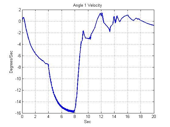
FOR mL=10 oz, the angle positions, controller firing and angle velocities for 1st and 2nd link, with FBBC are
shown in Figures 8 (a, b, c, d, e and f) respectively. For convenience, the angle positions are plotted in degrees.
FOR mL=20 oz, the angle positions, controller firing and angle velocities for 1st and 2nd link, with FBBC are
shown in Figures 9 (a, b, c, d, e and f) respectively.
For initial conditions to downward positions q1 = 0 , q2= 0 , q1 = = 90 , q2 = = 90 .
2 2
FOR mL=10 oz, the angle positions, controller firing and angle velocities for 1st and 2nd link, with FBBC are
shown in Figures 10 (a, b, c, d, e and f) respectively.
FOR mL=20 oz, the angle positions, controller firing and angle velocities for 1st and 2nd link, with FBBC are
shown in Figures 11 (a, b, c, d, e and f) respectively.
(a) (b)
2078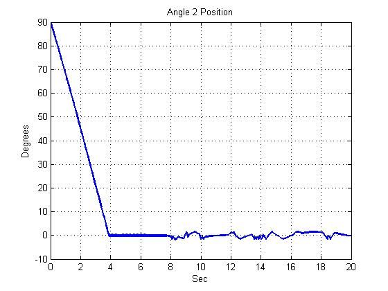
Aust. J. Basic & Appl. Sci., 5(12): 2071-2083, 2011

                            (b)                                                         (d)

                            (e)                                                         (f)

Fig. 8: The robot manipulators wit mL=10 oz under FBBC: (a) the angle 1 position, (b) the angle 2 position, (c)
        FBBC input for angle 1(d) FBBC input for angle 2, (e) Angle velocity for link 1 (f) Angle velocity for
        link 2.

                          (a)                                                           (b)

                           (c)                                                           (d)

                         (e)                                                      (f)
Fig. 9: The robot manipulators wit mL=20 oz under FBBC: (a) the angle 1 position, (b) the angle 2 position, (c)
        FBBC input for angle 1(d) FBBC input for angle 2, (e) Angle velocity for link 1 (f) Angle velocity for
        link 2.

                                                        2079
Aust. J. Basic & Appl. Sci., 5(12): 2071-2083, 2011

                          (a)                                                           (b)

                            (d)                                                         (c)

                          (e)                                                    (f)
Fig. 10: The robot manipulators wit mL=30 oz under FBBC: (a) the angle 1 position, (b) the angle 2 position, (c)
         FBBC input for angle 1(d) FBBC intput for angle 2, (e) Angle velocity for link 1 (f) Angle velocity for
         Link.

                           (a)                                                          (b)

                          (c)                                                            (d)

                                                        2080
Aust. J. Basic & Appl. Sci., 5(12): 2071-2083, 2011
(e) (f)
Fig. 11: The robot manipulators wit mL=40 oz under FBBC: (a) the angle 1 position, (b) the angle 2 position, (c)
FBBC input for angle 1(d) FBBC input for angle 2, (e) Angle velocity for link 1 (f) Angle velocity for
link 2.
From the results of the above simulations, Figures (8, 9, 10 and 11), (a, b, c, d, e and f) the controller is
tested with different payloads and movements, theses results show the good behavior of the FBBC. It can be
observed that the performance is satisfactory for both joints, indicating that the controller is capable of handling
the nonlinearities, couplings and uncertainties present in the system. The control input for link 1 and 2 generated
switches indiscriminately very fast and smooth.
Comparison Study:
In order to compare the proposed controller FBBC with the SMC in this work both controllers used the
same input and initial conditions, however, the output controller’s response are different. The complete design
of the SMC controller is describing in reference (Weibing Gao and James C. Hung, 1993). The comparison is
shown in tables and based on: the speed of convergences, maximum payload, amplitude and frequency.
Table 3: At fixed payload (mL) find the Convergence time, When mL=40 oz , A = 0.1 unit and ω = 0.01 rad /sec.
Initial value MSC FBBC
q1 & q2(Degree) q1 q2 (sec) q1 q2 (sec)
ω = 0.001 & A = 0.1
(sec) (sec)
o
90 9.2 4.1 8.5 4.7
180 o 9.4 4.3 10.5 5.2
270 o 10.1 5.3 12.2 6.6
o
360 11.1 7.1 14.9 8.1
Table 4: At fixed (ω,A) find the maximum payload (mL) , When ω=0.01 rad/sec and A=0.1 unit..
ω=0.01 (rad/sec) &
Initial value MSC FBBC
mL(oz) mL(oz)
1 & 2(Degree) q q
90 o 50 100
A=0.1(unit)
180 o 44 95
270 o 35 90
360 o 30 80
Table 5: At fixed payload (mL ,ω and, A) find the maximum Amplitude (A), When mL=40 oz, and ω = 0.001 rad/sec.
ω = 0.01 rad/sec &
Initial value SMC FBBC
A(Unit) A(Unit)
1 & 2(Degrees) q q
90o 0.95 5
o
180 0.93 3.6
mL=40 oz
270o 0.65 2.7
360o 0.6 2
In Table 3 the both controllers is tested with same initials conditions payload, frequency and amplitude
(mL= 40 oz, A = 0.1 unit and ω = 0.01 rad/sec) and seeking same desire positions this table showed that the
FBBC could reset robot links from any initial condition and with satisfactory settling time comparing with fast
controller as SMC. Table 4 shows the maximum payload can be handled by both controllers in same conditions,
which clearly shows the FBBC can carry load heavier than SMC. Table 5 shows the FBBC can track higher
amplitude then SMC. Form Table 6 shows the bang-bang controller can track high desired frequency better then
SMC.
2081Aust. J. Basic & Appl. Sci., 5(12): 2071-2083, 2011
Table 6: At fixed payload (ML) find the maximum frequency (ω), When mL=40 oz, and A=0.1 unit.
Initial value
MSC FBBC
mL=40 oz & A=0.1unit
ω(rad/sec) ω(rad/sec)
q1 & q2(Degree)
90o 0.001 0.1
180o 0.001 0.1
o
270 0.001 0.1
360o 0.001 0.1
Conclusions:
This paper propose MIMO fuzzy bang-bang controller. We demonstrate its operation with a simulated
model a real system application. The simulation model, representing robot no longer assume that the link masses
are concentrated at the centers of masses. Hence, each link has a moment of inertia. We also, assume that there
are frictions in the joints. Fuzzy controllers as known for absorbing the non-linearity of the systems and, as the
results show, it works well for the real nonlinear MIMO system. The bang-bang control is inherently time-
optimal, and this property is an important feature of FBBC.
Comparison between the FBBC and the SMC showed that FBBC is better than slide mode controller SMC
in handle big load, amplitude and frequency. The stability and optimality of FBBC were satisfied by the SMC-
lyapunov criterion and optimal bang-bang control theory respectively. Tuning of a new fuzzy bang-bang relay
controller is presented. The proposed scheme has stability support of sliding mode control due to its proximity
with non-linear Bang-Bang control theory. The new controller is simple in configuration with two level output,
similar to Bang-Bang relay controls and yet has a fuzzy decision making capability on its inputs side. The front-
end inputs are similar to standard fuzzy controllers based upon Mamdani implication but have a largest of
Maxima defuzzification output. The simulation results confirm the dynamic control capabilities of the FBBC are
superior to SMC under adverse conditions.
REFERENCES
Chang, S.Y., T.L. Huang and T.Y. Huang, 1995. “Fuzzy Bang-Bang Controller for servo Systems VIA
Optimal Path Estimation Method”, IEEE Catalogue, (95): 8025.
Chung-Chun, K. and L. Chia-Chang, 1994. “ Fuzzy-sliding Mode Controller Design for Tracking Control
of Non-linear Systems” Proc. American Control Conf. Baltimore, Maryland.
Elbrous, M.J, I. Yorgo and M.N. Alpaslan, 2002. “A new variable structure PID-Controller For Robot
Manipulators with Parameter Perturbations: An Augmented Sliding Surface Approach” 15th Trimennial world
congress, Baracelona, Spain IFAC.
Feng Lin, 2007. ”Robust control design: an optimal control approach” Wiley-Interscience, pp: 297- 316.
Fujitec, F., 1988. Flex-8800 Series Elevator Group Control System, Fujitec Co., Ltd., Osaka, Japan.
Grantham, K.H. Pang and A. Samy Mesbah, 1996. “Design of Bang-Bang Controller based on Fuzzy Neuro
Approach”, Proc. IEEE on Computer Aided Control system Design, Dearborn, MI.
Kendal, A., Y. Luo and Q. Zhang, 1991. “Stability Analysis of fuzzy Control Systems”. Fuzzy Sets and
Systems, 105(1): 33-48.
Kichert, W.J.M. and E.H. Mamdani, 1978. ”Analysis of A fuzzy Control Systems”, Fuzzy Sets and Systems,
1(1): 29-44.
L.-A.,Saad, M., B. Hebert and K. Al-Haddad, 1992. “An hybrid controller for a SCARA robot: Analysis
and simulation”. pp: 1299-1302.
Mahdi, S.A, I. Florin and T. Riad, 2009. ”Kinematic Modeling and Simulation of a SCARA Robot by
Using Solid Dynamics and Verification by MATLAB/Simulink” European Journal of Scientific Research ISSN
1450-216X, 37(3): 388-405.
Mazari, B. and F. Mefri, 2005. Fuzzy Hysteresis Control and Parameter Optimization of a Shunt Active
Power Filter‘, Journal of Information Science and Engineering., 21: 1139-1156.
Michael Athans and L. Peter Palb, 1966. Optimal Control, McGraw-Hill Inc.
Nomura, H., H. Hayashi and N. Wakami, 1992. ”A Learning Method of Fuzzy Inference Rules by Descent
Method”, IEEE, pp: 203-209.
Panda, G., R.R. Mishra, 2000. ”Fast Intelligent Relaying Using Fuzzy Logic Techniques“, Industrial
Technology 2000. Proceedings of IEEE International Conference.
Piotr Kulczycki, 2000. “Fuzzy Controller for Mechanical Systems”, IEEE Trans. On Fuzzy Systems, 8(5).
Rainer Palm, Driankov D. and H. Hellendoorn, 1997. “Model Based Fuzzy Control”, Springer-Verlag, New
York.
2082Aust. J. Basic & Appl. Sci., 5(12): 2071-2083, 2011
Richard, Y., J. Chiang and Roger Jang, 1994. “Fuzzy Logic attitude control f or Cassini Spacecraft”, Proc.
3rd IEEE Conference on Fuzzy Systems, Orlando, Florida, pp: 1532-1537.
Shinya, A., K. Masami and I. Jun, 2009. “Position Control of 2-Link SCARA Robot by using Internal
Model Control” MEM.FAC.ENG.OKA.UNI, 43: 49-54.
Slotine, J.J.E. and Li. Weiping, 1991. Applied Nonlinear Control, Prentice Hall, New Jersey.
Tanaka, K., M. Sugeno, 1992. Stability analysis and design of fuzzy control systems, Fuzzy Set and
Systems, 45: 135-156.
Thongchet, S. and S. Kuntanapreeda, 2001. “A fuzzy–Neural Bang-Bang Controller for Satellite Attitude
Control”, Proc. of SPIE–vol.4390, Application and Science of computational intelligence, IV: 97-104.
Ushiyama, R. and H. Walden, 1991. “Cold plate temperature regulation using fuzzy logic control”, SAE
Equation (Society of Automotive Engineers) Trans., pp: 1790-1801.
Weibing Gao and James C. Hung, 1993. “Variable Structure Control of Nonlinear Systems: A New
Approach” IEEE Transactions on industrial electronics, 40(1).
Yasunobu, S., S. Miyamoto, 1985. Automatic train operation by predictive fuzzy control, in: M. Sugeno
(Ed.), Industrail Applications of Fuzzy Control, North-Holland, Amsterdam, pp: 1-18.
2083You can also read