MARINE AC AND DC ELECTRICAL SYSTEMS SEMINAR BY - DENNIS KRUG and JOHN CHADWICK
←
→
Page content transcription
If your browser does not render page correctly, please read the page content below
MARINE AC AND DC
     ELECTRICAL SYSTEMS
          SEMINAR
              BY
DENNIS KRUG and JOHN CHADWICK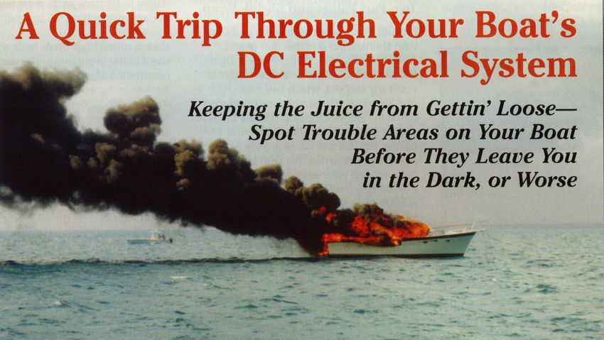
Topics
•   Electrical Basics
•   Wire Sizing and Connections
•   Circuit Protection
•   Batteries
•   Battery Charging Systems
    – Battery Chargers
    – Alternators
    – Solar and Wind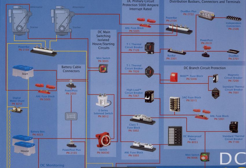
Topics
• Battery Monitors
• Inverters
• AC Systems
• Grounding Systems
• American Boat & Yacht Council, Inc. (ABYC) develops the
  consensus safety standards for the design, construction, equipage,
  maintenance, and repair of small craft. The development of uniform
  standards is the basis for industry-wide comparisons of products and
  performance.
• ABYC standards are minimum requirements for a safe design,
  construction and repair. Boaters should insist that builders, repairers
  and installers use these ABYC standards as a minimum. Their boating
  experience will be enhanced and the image of the marine industry
  justifiably improved..
                                                                   4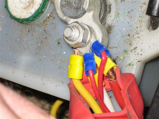
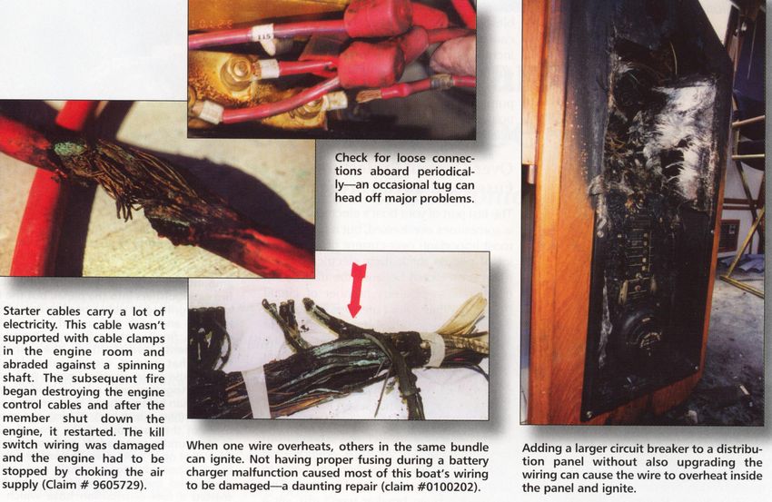
• Q:What is the most common problem on a
  boat?
• A:The most common problem on a boat is
  the failure of it’s electrical system.
• Q:What causes most boat fires?
• A:Most boat fires are directly related to a
  faulty electrical system
Electrical Basics
• Ohms law
• Ohms Law is a mathematical equation that shows
the relationship between Voltage, Current and
Resistance in an electrical circuit. It is stated as:
V=IxR
R=V/I
I=V/R
• Where
V = Voltage
I = Current
R = Resistance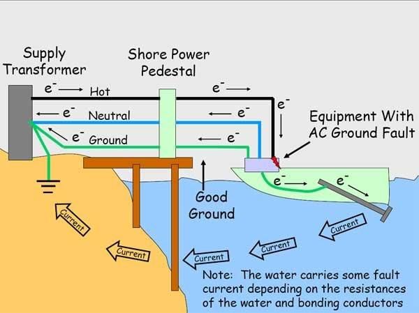
A SUMMARY OF WHAT THE MATH MEANS
                 (Which assumes the Unmentioned Value stays Constant)

• If voltage increases, there will be an increase in current flow (amps)
• If resistance (OHMS) increases Amperage will decrease
• In all circuits, voltage is lost as it travels through the circuit. This is
  referred to as VOLTAGE DROP.
   – Things Which Add Resistance To A Circuit:
       • Long wire runs to a load and back to the power source
       • Inadequate wire diameter (AWG Size)
       • Wire Type, (Material, # of Strands)
       • Loose or Corroded Connections
• Remember, the primary by-product of excessive resistance is
  heat!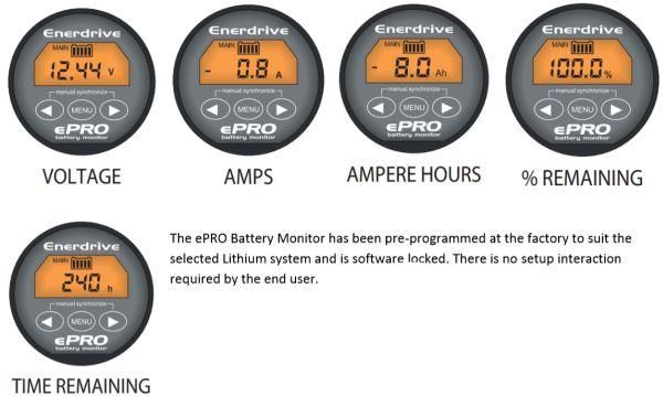
Wattage
Amps (current flow)
 x
Volts (system voltage)
 =
Watts (power, either production or
consumption)
What size wire do I need?

                            11
DC WIRE SIZING Blue Sea Circuit Wizard 12
MARINE GRADE WIRE
•   Marine Tinned Primary Wire

• Constructed to American Wire
  Gauge standards, AWG wire is up
  to twelve percent larger than the
  equivalent SAE wire sizes. AWG
  wire provides a greater current
  capacity when compared to SAE
  gauge wire.
• Marine Tinned Wire and Cables
  are manufactured from tin coated
  copper strands for maximum
  protection against corrosion,
  electrolysis and resists fatigue due
  to vibration and flexing.
• Rated at 600 volts and 105
  degrees C, the heavy duty
  insulation is resistant to heat and
  abrasion. Exceeds all UL1426, US
  Coast Guard Charterboat (CFR
  title 46) and ABYC standards.          13
MARINE GRADE TERMINALS
      AND TOOLS

                     14
ABYC E-11
• All conductors shall be supported and/or
clamped at least every 18 inches to relieve
strain on connections.
Like this Not This
15Circuit Protection
What is circuit protection?
• Circuit protection is the intentional installation of a "weak link" in an
electrical circuit. This is a fuse or circuit breaker, referred to here as a
circuit protection device.Circuit Protection What is the Circuit protection against? • Prevention of wire conductor overheating and resulting burning of the wire insulation is the primary reason to install a fuse or circuit breaker. In some cases they are also installed to protect electrical or electronic equipment from damage. How does fire start in an electrical circuit? • Fire results when too much amperage travels through a wire. Amperage is electron flow through a conductor. If too much amperage flows through a wire, enough heat can be generated to melt and burn the wire insulation or surrounding materials.
No Circuit Protection
   If you have electrical problems and
   your system looks something like
   this, then you needn't look much
   farther for the source of the
   problem.

 Unfortunately this is seen to often

                                         18
Circuit Protection
• What wires need to have Circuit Protection installed?
• The ideal answer is that every wire in the boat needs to be protected by a fuse
or a circuit breaker. The Circuit Protection Device must be correctly sized to the
wire it protects. As wires branch away from the batteries or other power source
and become progressively lighter, smaller CPDs must be installed at the
beginning of each wiring run.
• ABYC Standards exempt wiring between the batteries, the main battery switch
and the starter motor. It is not that these wires do not require CPDs, but that it is
often not practical to provide such protection. The diagram below shows where
ABYC standards for CPD placement. Measurements are maximum lengths
between the point of connection and the CPD. All 7" dimensions may be
increased to 40" if the conductor is enclosed in a sheath or enclosure in addition
to the wire insulation.Circuit Protection
BATTERIES
Ampere Hour Rating (Reference Rating)
• This is the number of amps which a battery can deliver for a
20-hour period. This test is also referred to as the 20-hour
rate. The larger the ampere hour rating, the more power the
battery can deliver over time.
Marine Cranking Amps (MCA)
• This is the number of amps a battery can deliver at 32
degrees fahrenheit for 30 seconds, and maintain at least a
voltage of 1.2 volts per cell. This differs from cold cranking
amps which are measured at 0 degrees fahrenheit.
Reserve Capacity (RC)
• This is the time, in minutes, for which a battery will deliver
25 amperes at 80 degrees fahrenheit. This represents the
time which the battery will continue to operate essential
accessories in the event of alternator or generator failure
or while the key is off.
Batteries
      • What happens to volts and
        amps?
      • Combining batteries in series
        multiplies voltage, capacity
        (Amp Hours) is unchanged
        (equivalent to the rating for
        one of the batteries in the
        series)
      • Combining batteries in
        parallel multiplies the
        amperage
      • Only combine batteries of
        like kind and vintage
Lead Batteries
Starter battery
The starter battery has
many thin plates in
parallel to achieve low
resistance with high
surface area. The starter
battery does not allow
deep cycling.
Deep-cycle battery
The deep-cycle battery has thick plates for
improved cycling abilities. The deep-cycle
battery generally allows about 300 cycles.Lead Batteries
Depth of Discharge Starter Battery Deep-cycle Battery
100% 12–15 cycles 150–200 cycles
50% 100–120 cycles 400–500 cycles
30% 130–150 cycles 1,000 and more cycles
Inexpensive and simple to manufacture; low cost per watt-hour
Low self-discharge; lowest among rechargeable batteries
Advantages
High specific power, capable of high discharge currents
Good low and high temperature performance
Low specific energy; poor weight-to-energy ratio
Slow charge; fully saturated charge takes 14-16 hours
Must be stored in charged condition to prevent sulfation
Limitations Limited cycle life; repeated deep-cycling reduces battery life
Flooded version requires watering
Transportation restrictions on the flooded type
Not environmentally friendlyAGM Batteries
Spill-proof through acid encapsulation in matting technology
High specific power, low internal resistance, responsive to load
Up to 5 times faster charge than with flooded technology
Advantages Better cycle life than with flooded systems
Water retention (oxygen and hydrogen combine to produce water)
Vibration resistance due to sandwich construction
Stands up well to cold temperature
Higher manufacturing cost than flooded (but cheaper than gel)
Sensitive to overcharging (gel has tighter tolerances than AGM)
Capacity has gradual decline (gel has a performance dome)
Limitations
Low specific energy
Must be stored in charged condition (less critical than flooded)
Not environmentally friendly (has less electrolyte, lead that flooded)Charging Characteristics
How long will they last ?
Sizing Your House Battery Bank
Sizing Your House Battery Bank
Battery Chargers

                   30
Ferroresonant Chargers
• The better chargers If you have one, replace it
work ok on wet cell
batteries
• Do not do a good job
on AGM and Gel
batteries
• May cause premature
battery failure because
of constant
overcharging
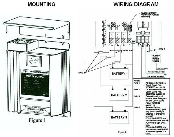
31Three Stage Battery Charger
32Battery Charger Wiring
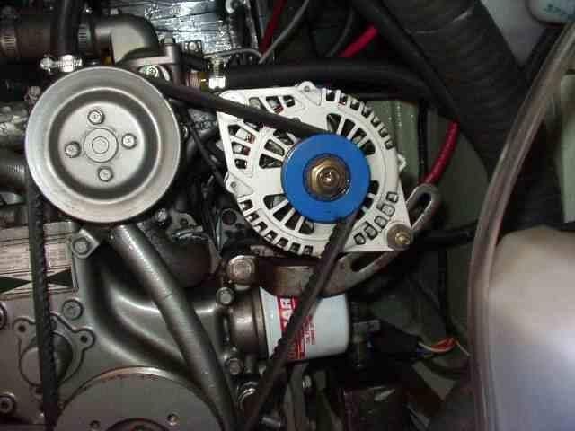
33Alternators
• Internal or external regulators
• In automotive type alternators, current for the alternator is supplied by
an internal regulator, which drives the alternator to a specific voltage
value (usually about 14.1 volts), which works great for a starting
battery, just like the one in your car.
• Deep cycle and sealed gel and AGM marine batteries require a more
complex program of charging voltages to achieve their optimal charge.
Multi-stage external voltage regulators, like the Balmar Max Charge
and ARS-5 enable the alternator to vary charging voltages, based on the
battery’s temperature, chemistry (flooded, gel or AGM types) and level
of discharge, to ensure that batteries are recharged quickly and safely.
34SMART REGULATORS
35Alternators
• The Rule of thumb is that the alternator
output in amps should not be less than 25%
of the battery capacity in amp hours for
lead batteries and 40% for AGM.
• You can figure 1 hp draw per 25 amps (12
volt) at maximum output.
Highest
Belt Type Belt Width Max. HP Load Recommended
Output
80A @ 12V, 30A
Single Vee 3/8 3.5
@ 24V
110A @ 12V, 45A
Single Vee 1/2 4.5
@ 24V
310A @ 12V, 36
Dual Vee 1/2 12
220A @ 24VCharging Multiple Battery Banks
The Battery Isolator
• IT’S IMPORTANT TO REMEMBER
THAT IF A BATTERY ISOLATOR IS
INSTALLED, VOLTAGE SENSING FOR
THE ALTERNATOR MUST BE DONE
AT THE BATTERIES, OR AT LEAST ON
THE BATTERY SIDE OF THE
ISOLATOR.
• THIS IS DUE TO THE INHERENT 0.7 V
LOSS THROUGH THE ISOLATOR
DIODES.
• ALSO, ISOLATORS MUST BE RATED
FOR THE MAXIMUM ALTERNATOR
AMPERAGE OUTPUT
• Battery Isolators are made with two
or more silicon diodes that act like
check valves. The diodes will pass
current from the charging source to
the batteries, but will not pass current
backward from one battery to the
37
other or back to the charging source.A Better Way
BATTERY COMBINERS
• Automatically combines battery banks
during the charging cycle and isolates
under discharge
• Ignition protected - safe for installation
aboard gasoline-powered boats
• Activates from any charging source -
alternators, battery chargers, or solar
panels
• Requires circuit protection device at • The ACR has two parts:
batteries • A relay – a switch that is activated by an
electrically powered magnetic coil.
• An electronic circuit that senses the voltage
level of the boat’s batteries and signals the
relay switch:
• Closed when voltage is high (the ACR’s
COMBINE voltage)
• Open when voltage is lower (the ACR’s
UNDERVOLTAGE voltage)
38Battery Combiner Diagram
39Effect of Solar and Wind Energy on Marine Battery Charging
How do you know if your
batteries are properly charged?
Battery Monitors

                                            • Read your battery bank like a fuel
•   Electrical Specifications
                                              gauge
•   Voltage Measurement
•   0 - 35.0 VDC (+/-0.01 V resolution)
                                            • Provides critical information about
                                              the status of your battery bank
•   Current Measurement
•   -500 - 500 A                            • Displays voltage, current, consumed
                                              amphours and remaining battery
•   Amp-Hour Measurement
                                              capacity
•   High range +/- 200 - 1,999 Ah (1 hour
    resolution)                             • Secondary battery bank voltage
•   Battery Capacity Range                    monitoring
•   200 - 2000 Ah                                                         42
What they tell you
INVERTERS
•   A-25.5 REQUIREMENTS - IN GENERAL
    A-25.5.1 If the inverter also serves as a battery charger, it shall also meet the requirements of ABYC A-20, Battery Charging Devices.
    NOTE: An inverter incorporating a battery charging circuit that meets UL 458, Power Converters/Inverters and Power Converter/Inverter Systems for Land Vehicles and Marine
    Crafts, and Supplement SA, Marine Power Converters/Inverters and Power Converter/Inverter Systems, need not meet UL 1236 as referenced in ABYC A-20, Battery Charging
    Devices.
    A-25.5.2 Output voltage and frequency shall be in accordance with ABYC E-8, Alternating Current (AC) Electrical Systems On Boats.
    EXCEPTION: Inverters dedicated to supply power to only a specific piece of equipment.
    A-25.5.3 All marine power inverters shall meet the applicable requirements of UL 458, Power Converters/Inverters and Power Converter/Inverter Systems for Land Vehicles and
    Marine Crafts, and Supplement SA, Marine Power Converters/Inverters and Power Converter/Inverter Systems.
    A-25.5.4 Power inverters shall be automatically controlled to provide frequency and voltage regulation compatible with section 27 of UL 1248, Engine-Generator Assemblies for
    Use in Recreational Vehicles.
    A-25.5.5 Power inverters shall provide isolation of the AC output from the DC supply circuit.
    A-25.5.6 Integral inverter receptacle shall be protected by an integral GFCI device in accordance with ABYC E-8, Alternating Current (AC) Electrical Systems On Boats. The
    receptacle is to be used only with cord connected loads.
    A-25.5.7 A visible means (e.g., voltmeter or lamp) of determining that the inverter is "on line" and/or in "stand-by" mode shall be provided at the main electrical distribution
    panel.
    A-25.5.8 A warning label shall be provided at the main electrical panel to indicate that the electrical system includes an inverter. See A-25.10.1.
    A-25.5.9 Grommets, bushings, or other means shall be provided to prevent chafing of wires passing through the inverter case.
    A-25.5.10 Safety signs and labels shall comply with ABYC T-5, Safety Signs and Labels, and shall contain at least the following informational elements:
    A-25.5.10.1 The signal word for the hazard intensity level; and
    A-25.5.10.2 the nature of the hazard; and
    A-25.5.10.3 the consequences that can result if the instructions to avoid the hazard are not followed; and
    A-25.5.10.4 instructions on how to avoid the hazard.
•   A-25.6 INSTALLATION AND LOCATION
    A-25.6.1 The installation and protection of electrical wiring associated with inverters shall comply with ABYC standards ABYC E-8, Alternating Current (AC) Electrical
    Systems on Boats, and ABYC E-9, Direct Current (DC) Electrical Systems On Boats.
    A-25.6.2 Inverters shall be installed:
    A-25.6.2.1 in a ventilated, dry, accessible location; and
    A-25.6.2.2 where the ambient temperature will not exceed 122°F (50°C); and
    A-25.6.2.3 away from heat sources, such as dry engine exhaust and other heat producing devices.
    A-25.6.3 Inverters shall not be installed directly over batteries.
    A-25.6.4 Inverter controls shall be readily accessible.
    A-25.6.5 Inverters shall be located so that hinged covers and access plates can be opened.
    A-25.6.6 Inverters shall be securely fastened to bulkheads or other vessel structural parts.
    A-25.6.7 When mounted, the base of the inverter shall be at least two feet above normal bilge water, or protected so it is not subject to bilge splash.
    A-25.6.8 The installer shall provide physical protection from falling objects or drippage unless such provision is integral to the inverter.
    A-25.6.9 Overcurrent protection in the DC input circuit shall comply with the requirements of ABYC E-9. This protection is intended to protect the wiring in the DC circuit.
    NOTE: See ABYC E-9 for battery switch requirements.
    A-25.6.10 If ground fault circuit interruption is provided in the output of the inverter, the ground fault interrupter shall not be located in a compartment requiring ignition
    protection, unless it is ignition protected as provided in SAE J-1171 or UL 1500.
    A-25.6.11 An inverter that does not have an integral ground fault protection device and is installed so that GFCI protection is required by ABYC E-8, shall have the required
    GFCI device(s) specified by the inverter manufacturer as to GFCI manufacturer and model number.
    NOTE: Harmonic distortion of the AC output waveform from some inverters may affect the operation of some GFCI devices.
    A-25.6.12 Power inverters installed in spaces requiring ignition protection shall meet the ignition protection requirements of SAE J1171 or UL 1500. See A-25.10.2 for labeling
    requirements.
    NOTE: For information on spaces requiring ignition protected equipment see 33 CFR 183.410; ABYC A-1, Marine Liquefied Petroleum Gas (LPG) Systems; ABYC A-22,
    Marine Compressed Natural Gas (CNG) Systems; ABYC E-8, Alternating Current (AC) Electrical Systems On Boats; ABYC E-9, Direct Current (DC) Electrical Systems On
    Boats; and ABYC H-24, Gasoline Fuel Systems.
    A-25.6.13 A means to achieve strain relief shall be installed within six inches of the case unless a strain relief method is integral with the case for wiring passing through.
•   A-25.7 AC WIRING CONNECTIONS
    A-25.7.1 ABYC E-8, Alternating Current (AC) Electrical Systems On Boats, requires a grounded neutral system. The neutral for AC power sources shall be grounded only at the
    following points:
    A-25.7.1.1 The shore power neutral is grounded through the shore power cable and shall not be grounded on board the boat.
    A-25.7.1.2 The inverter output neutral shall be grounded at the inverter.
    A-25.7.1.2.1 The inverter/charger output neutral shall be grounded at the inverter/charger.
AC Systems
Galvanic Isolators
•   What is a galvanic isolator and why should my shore power system have
    one?
•   A galvanic isolator is a device used to block low voltage DC currents coming on board
    your boat on the shore power ground wire. These currents could cause corrosion to your
    underwater metals; through hulls, propeller, shaft etc.
•   Boats in a marina plugged into shore power all act as a giant battery. They are all
    connected together by the green shore power ground wire, which is (or should be)
    connected to their DC grounds, engine block, and bonded underwater metals. (Required
    by ABYC If the boats are in salt water then that forms an electrolyte and the dissimilar
    metals connected together act as a battery, causing corrosion.
GALVANIC ISOLATOR
OLD STYLE ISOLATOR
• DUE TO THE INHERENT
VOLTAGE DROP THAT OCCURS
ACROSS A DIODE – TYPICALLY
0.6 V TO 0.7 V –
• GALVANIC ISOLATORS CAN BE
USED TO EFFECTIVELY BLOCK
GALVANIC CURRENTS UP OT
ABOUT 1.4 V. BY PUTTING TWO
DIODES IN SERIES 48Fail Safe Galvanic Isolators
• Fail-safe construction featuring
Fail-Safe Plus™ and Fail-Safe
Max™ technology
• Certified to ABYC A-28 July
2008 publication
• No monitoring system required
• Highest AC fault current ratings
available
• Ignition protected
• Maintenance-free solid-state
design
• Rated for high levels of lightning
current
• Very low DC leakage current49
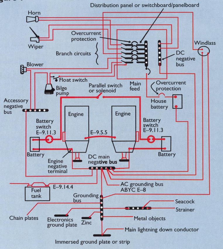
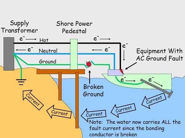
allowedGrounding System
Multiple Roles of the Grounding System
• Prevent electrical shock hazard to people on board
– In the event of an electrical fault in a AC appliance it is
essential to provide a reliable path for this fault current back to
the source of power, not through the person coming into contact
with the device
• Prevent stray current corrosion
– Equalize voltage potentials among dissimilar metal objects
exposed to seawater.
Bonding systems – and cathodic protection (properly sized and
placed anodes)
• Lightning Protection
• Radio Frequency Interference reduction
• Note : The AC Ground buss (green wire) is connected to the DC
Negative BussGrounding System
Electric Shock
           Drowning
           Good
           Ground

Broken
Ground
Effects of a Lightning Strike
Lightning Grounding
•   Connect a AWG 4 battery cable from the base of your aluminum mast to the
    nearest keel bolt from external ballast. If you have internal ballast, you should
    install a lightning ground plate. One square foot is recommended for use in salt
    water; fresh water requires much more. Do not rely on a thru-hull or a sintered
    bronze radio ground (e.g. Dynaplate) for use as a lightning ground.

•   For additional comfort, also run a 6 AWG wire from your keel bolt or ground plate
    to the upper shroud chainplates, and to your headstay chainplate. Don't bother
    with the backstay if it is interrupted with antenna insulators. Have each of the
    cables that are used for lightning ground wires lead as directly as possible to the
    same keel bolt, with any necessary bends being smooth and gradual.

•   Given that you have grounded your mast solidly to the ocean, your mast will be at
    exactly the same electric potential as the ocean. There is no chance that you
    can dissipate the charge between the ocean and the atmosphere, so don't bother
    with a static dissipater at the masthead. Wire "bottle brush" static dissipaters
    may be useful to dissipate seagulls.
Recommended Books Boatowner’s Mechanical and Electrical Manual, third edition Nigel Calder Maintain, repair, and improve a boat’s essential systems. A comprehensive guide to electrical, mechanical, and propulsion systems. Sailboat Electrical Systems: Improvement, Wiring and Repair Don Casey A basic treatment for recreational sailboats and powerboats. A good book for maintenance and repair. Sailboat Electrics Simplified Don Casey How to install wiring, make good, safe connections, match you battery bank and alternator to your needs, troubleshoot problems quickly, and 55 avoid shore power problems.
Recommended Books
• Powerboater’s Guide to Electrical Systems: Maintenance,
  Troubleshooting and Improvements, second edition
  Ed Sherman
  Focused on power cruisers, the author is a recognized authority on
  electrical practice and is well respected by boat builders and marine
  electricians.
• Advanced Marine Electrics and Electronics Troubleshooting
  Ed Sherman
  Targeted at trade professionals. Boat builders, installers, electricians
  and boatyard owners will want this book for its insight into new tools
  and techniques for tracking down problems. The advanced boat owner
  will benefit as well.
• Boatowner’s Illustrated – Electrical Handbook, second edition
  Charlie Wing                                                             56
  Great for learning about a boat’s electrical system.
Recommended Web Sites
• Bluesea.com
• ABYC

                            57
SUMMARY • Each circuit must have its own properly rated circuit protection device. • Only the starter motor circuit is exempt from having a circuit protection device • Check connections for corrosion, loosening. • Use marine grade “boat cable” • Use marine grade connectors • Support wiring every 18 inches • Make sure all wire runs are routed above the bilge • Ensure that the boat has a proper grounding system
You can also read