Rosemount 644 Temperature Transmitter - with 4-20 mA HART Protocol (Revision 5 and 7) - Emerson
←
→
Page content transcription
If your browser does not render page correctly, please read the page content below
Quick Start Guide
                          00825-0200-4728, Rev HC
                                         May 2019

Rosemount™ 644 Temperature
Transmitter

with 4–20 mA HART® Protocol (Revision 5
and 7)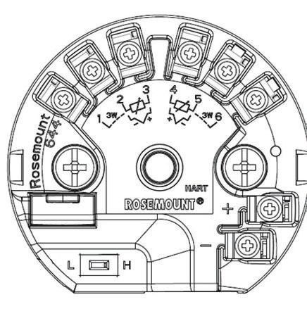
Quick Start Guide                                                                                   May 2019

Safety messages

      NOTICE
      This guide provides basic guidelines for installing the Rosemount™ 644 Temperature Transmitter. It
      does not provide instructions for detailed configuration, diagnostics, maintenance, service,
      troubleshooting, or installation. Refer to the Rosemount 644 Reference Manual for more instruction.
      The manual and this guide are also available electronically on Emerson.com/Rosemount.

      Important
      Read this manual before working with the product. For personal and system safety, and for optimum
      product performance, make sure to thoroughly understand the contents before installing, using, or
      maintaining this product. The United States has two toll-free assistance numbers and one international
      number.
      Customer Central: 1-800-999-9307 (7:00 a.m. to 7:00 p.m. Central Standard Time)
      National Response Center: 1-800-654-7768 (24 hours a day). Equipment service needs
      International: 1-(952)-906-8888

          WARNING
         Physical access
         Unauthorized personnel may potentially cause significant damage to and/or misconfiguration of
         end users’ equipment. This could be intentional or unintentional and needs to be protected against.
         Physical security is an important part of any security program and fundamental to protecting your
         system. Restrict physical access by unauthorized personnel to protect end users’ assets. This is true
         for all systems used within the facility.

          WARNING
         Follow instructions
         Failure to follow these installation guidelines could result in death or serious injury.
         Ensure only qualified personnel perform the installation.

          WARNING
         Explosions
         Explosions could result in death or serious injury.
              Installation of the transmitters in a hazardous environment must be in accordance with the
              appropriate local, national, and international standards, codes, and practices. Please review the
              Product Certifications section for any restrictions associated with a safe installation.
              Do not remove the connection head cover in explosive atmospheres when the circuit is live.
              Before connecting a handheld communicator in an explosive atmosphere, ensure the
              instruments are installed in accordance with intrinsically safe or non-incendive field wiring
              practices.Verify the operating atmosphere of the transmitter is consistent with the appropriate
              hazardous locations certifications.
              All connection head covers must be fully engaged to meet explosion-proof requirements.

2                                                                                    Emerson.com/Rosemount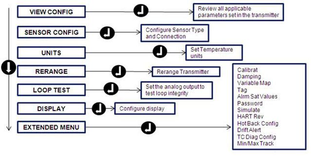
May 2019                                                                                                         Quick Start Guide

               WARNING
             Process leaks
             Process leaks could result in death or serious injury.
                   Do not remove the thermowell while in operation.
                   Install and tighten thermowells and sensors before applying pressure.

               WARNING
             Electrical shock
             Electrical shock could cause death or serious injury.
             Avoid contact with the leads and terminals. High voltage that may be present on leads can cause
             electrical shock.

Contents
System readiness......................................................................................................................... 5
Transmitter installation................................................................................................................ 6
Safety instrumented systems..................................................................................................... 24
Product certifications................................................................................................................. 25

Quick Start Guide                                                                                                                        3
Quick Start Guide               May 2019

4                   Emerson.com/Rosemount
May 2019                                                                         Quick Start Guide

1          System readiness
1.1        Confirm HART® revision capability
           • If using HART based control or asset management systems, confirm the
             HART capability of those systems prior to transmitter installation. Not all
             systems are capable of communicating with HART Revision 7 Protocol.
             You can configure thie transmitter for either HART Revision 5 or 7.

1.2        Confirm correct device driver
           Procedure
               1. Verify the latest Device Driver files are loaded on your systems to
                  ensure proper communications.
               2. Download the latest Device Driver at Emerson.com/Device-Install-
                  Kits/Device-Install-Kit-Search
                    Table 1-1 provides the information necessary to ensure the correct
                    Device Driver files and documentation are being used.
Table 1-1: Device Revisions and Files

Software     NAMUR       HART®        HART       Device    Manual                Changes to
date         Software    Software     Universal revision(2 Document              Software(3)
             revision    revision     revision(1 )         Number
                                      )

June 2012 1.1.1          3            5           8            00809-0100-47 See (3) for list of
                                                               28            changes.
                                      7           9

(1) NAMUR software revision is located on the hardware tag of the device. HART software
    revision can be read using a HART communication tool.
(2) Device Driver file names use Device and DD Revision, e.g. 10_01. HART Protocol is designed
    to enable legacy device driver revisions to continue to communicate with new HART devices.
    To access new functionality, download the new Device Driver. Emerson recommends
    downloading new Device Driver files to ensure full functionality.
(3) HART Revision 5 and 7 Selectable, Dual Sensor support, Safety Certified, Advanced
    Diagnostics (if ordered), Enhanced Accuracy and Stability (if ordered).

Quick Start Guide                                                                                  5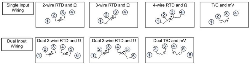
Quick Start Guide                                                               May 2019

2         Transmitter installation
2.1       Set the alarm switch
          Set the alarm switch before putting the device into operation.

          Procedure
              1. Set the loop to manual (if applicable) and disconnect the power
              2. Remove the LCD display by detaching from the transmitter (if
                 applicable).
              3. Set the switch to the desired position.
                    H indicates High; L indicates Low.

              4. Reattach the LCD display to the transmitter (if applicable).
              5. Reattach the housing cover. Ensure covers must be fully engaged to
                 meet explosion-proof requirements.
              6. Apply power and set the loop to automatic control (if applicable).
          Example

          Figure 2-1: Alarm Switch Placement

           Rosemount™ 644 Transmitter               Rosemount 644 Field Mount

                                              A

          A. Alarm switch

          Note
          If using an LCD display, remove the display by detaching it from the top of
          the device, set the switch to the desired position, reattach the LCD display,
          and reattach the housing cover. Enclosure covers must be fully engaged to
          meet explosion-proof requirements.

6                                                                  Emerson.com/Rosemount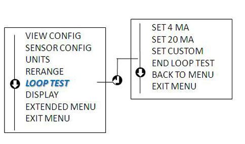
May 2019                                                                     Quick Start Guide

2.2        Verify configuration
           Upon receiving your transmitter, verify its configuration using any HART®-
           compliant configuration tool. See the Rosemount™ 644 Reference Manual
           for configuration instructions using AMS Device Manager.
           The transmitter communicates using the Field Communicator
           (communication requires a loop resistance between 250 and 1100 ohms).
           Do not operate when power is below 12 Vdc at the transmitter terminal. See
           the Field Communicator Reference Manual for more information.

2.2.1      Verify configuration with a Field Communicator
           To verify configuration, you must install a Rosemount™ 644 DD (Device
           Descriptor) on the Field Communicator.
           Fast Key sequences for the latest DD are shown in Table 2-1. For Fast Key
           sequences using legacy DD's, contact your local Emerson representative.
           Perform the following steps to determine if an upgrade is required.

           Procedure
               1. Connect the sensor.
                    See the wiring diagram located on the device’s top label.
               2. Connect the bench power supply to the power terminals (“+” or “–”).
               3. Connect a Field Communicator to the loop across a loop resistor or at
                  the power/signal terminals on the transmitter.
           The following message will appear if the communicator has a previous
           version of the DDs:
           Device Description Not Installed…The Device
           Description for manufacturer 0x26 model 0x2618 dev
           rev 8/9 is not installed on the System Card…see
           Programming Utility for details on Device
           Description updates…Do you wish to proceed in
           forward compatibility mode?
           If this notice does not appear, the latest DD is installed. If the latest version is
           not available, the communicator will communicate properly; however, when
           the transmitter is configured to utilize advanced transmitter features, there
           will be trouble communicating and a prompt to turn off the communicator
           will display. To prevent this from happening, upgrade to the latest DD or
           answer NO to the question and default to the generic transmitter
           functionality.

Quick Start Guide                                                                            7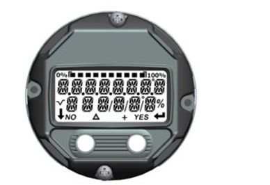
Quick Start Guide                                                              May 2019

          Note
          Emerson recommends installing the latest DD to access the complete
          functionality. Visit Emerson.com/Field-Communicator for information on
          updating the DD Library.

2.2.2     Field Communicator user interface
          Two user interfaces are available to configure this device.
          Figure 2-2 may be used for transmitter configuration and startup.

          Figure 2-2: Device Dashboard Field Communicator Interface

          Table 2-1: Device Revision 8 and 9 (HART® 5 and 7), DD Revision 1 Fast
          Key Sequence

           Function                  HART 5                    HART 7

           Alarm Values              2, 2, 5, 6                2, 2, 5, 6

           Analog Calibration        3, 4, 5                   3, 4, 5

           Analog Output             2, 2, 5, 1                2, 2, 5, 1

           Average Temperature       2, 2, 3, 3                2, 2, 3, 3
           Setup

           Burst Mode                2, 2, 8, 4                2, 2, 8, 4

           Comm Status               N/A                       1, 2

           Configure Additional      N/A                       2, 2, 8, 4, 7
           Messages

           Configure Hot Backup ™    2, 2, 4, 1, 3             2, 2, 4, 1, 3

           D/A Trim                  3, 4, 4, 1                3, 4, 4, 1

8                                                                 Emerson.com/Rosemount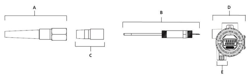
May 2019                                                                 Quick Start Guide

           Table 2-1: Device Revision 8 and 9 (HART® 5 and 7), DD Revision 1 Fast
           Key Sequence (continued)
            Function                   HART 5               HART 7

            Damping Values             2, 2, 1, 5           2, 2, 1, 6

            Date                       2, 2, 7, 1, 2        2, 2, 7, 1, 3

            Display Setup              2, 1, 4              2, 1, 4

            Descriptor                 2, 2, 7, 1, 4        2, 2, 7, 1, 5

            Device Information         1, 8, 1              1, 8, 1

            Differential Temperature   2, 2, 3, 1           2, 2, 3, 1
            Setup

            Drift Alert                2, 2, 4, 2           2, 2, 4, 2

            Filter 50/60 Hz            2, 2, 7, 4, 1        2, 2, 7, 4, 1

            First Good Temperature     2, 2, 3, 2           2, 2, 3, 2
            Setup

            Hardware Revision          1, 8, 2, 3           1, 8, 2, 3

            HART Lock                  N/A                  2, 2, 9, 2

            Intermittent Sensor        2, 2, 7, 4, 2        2, 2, 7, 4, 2
            Detect

            Loop Test                  3, 5, 1              3, 5, 1

            Locate Device              N/A                  3, 4, 6, 2

            Lock Status                N/A                  1, 8, 3, 8

            LRV (Lower Range Value)    2, 2, 5, 5, 3        2, 2, 5, 5, 3

            LSL (Lower Sensor Limit)   2, 2, 1, 7, 2        2, 2, 1, 8, 2

            Message                    2, 2, 7, 1, 3        2, 2, 7, 1, 4

            Open Sensor Holdoff        2, 2, 7, 3           2, 2, 7, 3

            Percent Range              2, 2, 5, 2           2, 2, 5, 2

            Sensor 1 Configuration     2, 1, 1              2, 1, 1

            Sensor 2 Configuration     2, 1, 1              2, 1, 1

            Sensor 1 Serial Number     2, 2, 1, 6           2, 2, 1, 7

            Sensor 2 Serial Number     2, 2, 2, 7           2, 2, 2, 8

            Sensor 1 Type              2, 2, 1, 2           2, 2, 1, 3

            Sensor 2 Type              2, 2, 2, 2           2, 2, 2, 3

            Sensor 1 Unit              2, 2, 1, 4           2, 2, 1, 5

Quick Start Guide                                                                       9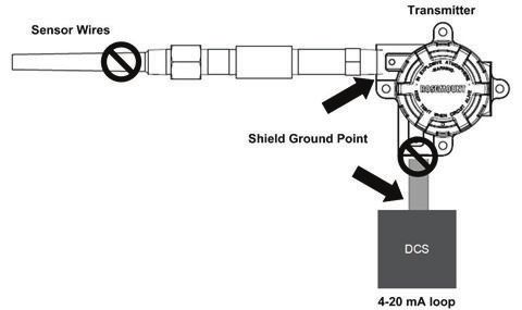
Quick Start Guide                                                              May 2019

          Table 2-1: Device Revision 8 and 9 (HART® 5 and 7), DD Revision 1 Fast
          Key Sequence (continued)
           Function                   HART 5                   HART 7

           Sensor 2 Unit              2, 2, 2, 4               2, 2, 2, 5

           Sensor 1 Status            N/A                      2, 2, 1, 2

           Sensor 2 Status            N/A                      2, 2, 2, 2

           Simulate Digital Signal    N/A                      3, 5, 2

           Software Revision          1, 8, 2, 4               1, 8, 2, 4

           Tag                        2, 2, 7, 1, 1            2, 2, 7, 1, 1

           Long Tag                   N/A                      2, 2, 7, 1, 2

           Terminal Temperature       2, 2, 7, 1               2, 2, 8, 1

           URV (Upper Range Value)    2, 2, 5, 5, 2            2, 2, 5, 5, 2

           USL (Upper Sensor Limit)   2, 2, 1, 7, 2            2, 2, 1, 8, 2

           Variable Mapping           2, 2, 8, 5               2, 2, 8, 5

           2-wire Offset Sensor 1     2, 2, 1, 9               2, 2, 1, 10

           2-wire Offset Sensor 2     2, 2, 2, 9               2, 2, 2, 10

2.2.3     Input or verify Callendar Van-Dusen constants
          If using sensor matching with this combination of a transmitter and sensor,
          verify the constants input.

          Procedure
              1. From the HOME screen, select2 Configure → 2 Manual Setup → 1
                 Sensor.
              2. Set the control loop to manual and select OK.
              3. At the ENTER SENSOR TYPE prompt, select Cal VanDusen.
              4. At the ENTER SENSOR CONNECTION prompt, select the
                 appropriate number of wires.
              5. Enter the Ro, Alpha, Delta, and Beta values from the stainless steel
                 tag attached to the special-order sensor when prompted.
              6. Return the control loop to automatic control and select OK.
              7. To disable the transmitter-sensor matching feature from the HOME
                 screen select 2 Configure → 2 Manual Setup → 1 Sensor → 10
                 Sensor Matching-CVD.
              8. Choose the appropriate sensor type from the ENTER SENSOR
                 TYPE prompt.

10                                                                Emerson.com/Rosemount
May 2019 Quick Start Guide
2.2.4 Verify configuration with local operator interface (LOI)
The optional LOI can be used for commissioning the device. The LOI is a two-
button design. To activate the LOI, push any button.
LOI button functionality is shown on the bottom corners of the display. See
Table 2-2 and Figure 2-4 for button operation and menu information.
Figure 2-3: Local Operator Interface
Table 2-2: LOI Button Operation
Button
Left No SCROLL
Right Yes ENTER
Quick Start Guide 11Quick Start Guide May 2019
Figure 2-4: LOI Menu
2.2.5 Switch HART® Revision mode
Not all systems are capable of communicating with HART Revision 7
Protocol. You can configure this transmitter for either HART Revision 5 or 7
using a HART capable configuration tool.
Updated configuration menus include a HART Universal Revision parameter
that can be configured to 5 or 7 if accessible by your system. See Table 2-1
for the Fast Key sequence.
If the HART configuration tool is not capable of communicating with HART
Revision 7, the configuration menus in Table 2-1 will not be available. To
switch the HART Universal Revision parameter from generic mode, follow
the instructions below.
Procedure
Go to Configure → Manual Setup → Device Information → Identification
→ Message.
a) To change your device to HART Revision 7, enter HART7 in the
Message field.
b) To change your device to HART Revision 5, enter HART5 in the
Message field.
Note
See Table 2-1 to change HART Revision when the correct Device Driver is
loaded.
12 Emerson.com/RosemountMay 2019 Quick Start Guide
2.3 Mount the transmitter
Mount the transmitter at a high point in the conduit run to prevent moisture
from draining into the transmitter housing.
2.3.1 Head mount transmitter with DIN plate style sensor installation
Procedure
1. Attach the thermowell to the pipe or process container wall.
2. Install and tighten the thermowell before applying process pressure.
3. Verify the transmitter failure mode switch position.
4. Assemble the transmitter to the sensor. Push the transmitter
mounting screws through the sensor mounting plate.
5. Wire the sensor to the transmitter.
6. Insert the transmitter-sensor assembly into the connection head.
a) Thread the transmitter mounting screw into the connection
head mounting holes.
b) Assemble the extension to the connection head.
c) Insert the assembly into the thermowell.
7. If using a cable gland, properly attach the cable gland to a housing
conduit entry.
8. Insert the shielded cable leads into the connection head through the
cable entry.
9. Connect the shielded power cable leads to the transmitter power
terminals.
Avoid contact with sensor leads and sensor connections.
10. Connect and tighten the cable gland.
11. Install and tighten the connection head cover.
Enclosure covers must be fully engaged to meet explosion-proof
requirements.
Quick Start Guide 13Quick Start Guide May 2019
A. Connection head cover
B. Connection head
C. Thermowell
D. Transmitter mounting screws
E. Integral mount sensor with flying leads
F. Extension
2.3.2 Head mount transmitter with threaded sensor installation (two or
three conduit entries)
Procedure
1. Attach the thermowell to the pipe or process container wall.
2. Install and tighten thermowells before applying process pressure.
3. Attach necessary extension nipples and adapters to the thermowell.
4. Seal the nipple and adapter threads with silicone tape.
5. Screw the sensor into the thermowell. Install drain seals if required
for severe environments or to satisfy code requirements.
6. Verify the transmitter failure mode switch is in the desired position.
7. Verify the correct installation of Integral Transient Protection (option
code T1).
a) Ensure the transient protector unit is firmly connected to the
transmitter puck assembly.
b) Ensure the transient protector power leads are adequately
secured under the transmitter power terminal screws.
c) Verify the transient protector’s ground wire is secured to the
internal ground screw found within the universal head.
Note
The transient protector requires the use of an enclosure of at least
3.5-in. (89 mm) in diameter.
8. Pull the sensor wiring leads through the universal head and
transmitter center hole.
14 Emerson.com/RosemountMay 2019 Quick Start Guide
9. Mount the transmitter in the universal head by threading the
transmitter mounting screws into the universal head mounting
holes.
10. Mount the transmitter-sensor assembly into the thermowell, or
remote mount if desired.
11. Seal adapter threads with silicone tape.
12. Pull the field wiring leads through the conduit into the universal
head. Attach the sensor and power leads to the transmitter.
Avoid contact with other terminals.
13. Install and tighten the universal head cover.
Enclosure covers must be fully engaged to meet explosion-proof
requirements.
Example
A. Threaded thermowell
B. Threaded style sensor
C. Standard extension
D. Universal head (transmitter inside)
E. Conduit entry
2.3.3 Field mount transmitter with threaded sensor installation
Procedure
1. Attach the thermowell to the pipe or process container wall. Install
and tighten thermowells before applying process pressure.
2. Attach necessary extension nipples and adapters to the thermowell.
3. Seal the nipple and adapter threads with silicone tape.
4. Screw the sensor into the thermowell. Install drain seals if required
for severe environments or to satisfy code requirements.
5. Verify the transmitter failure mode switch is in the desired position.
6. Mount the transmitter-sensor assembly into the thermowell or
remote mount if desired.
7. Seal adapter threads with silicone tape.
Quick Start Guide 15Quick Start Guide May 2019
8. Pull the field wiring leads through the conduit into the field mount
housing. Wire the sensor and power leads to the transmitter.
Avoid contact with other terminals.
9. Install and tighten the covers of two compartments.
Enclosure covers must be fully engaged to meet explosion-proof
requirements.
Example
A D
B
C
E
A. Threaded thermowell
B. Threaded style sensor
C. Standard extension
D. Field mount housing (transmitter inside)
E. Conduit entry
2.4 Wire and apply power
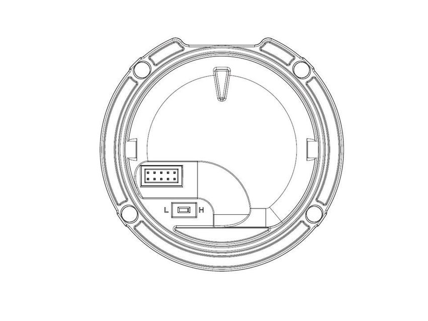
2.4.1 Wire the sensor to the transmitter
The wiring diagram is located on the device’s top label below the terminal
screws.
Figure 2-5: Rosemount™ 644 Head Mount Transmitter
16 Emerson.com/RosemountMay 2019 Quick Start Guide
Figure 2-6: Rosemount 644 Head Mount - Single and Dual Input Wiring
Diagrams
• The transmitter must be configured for at least a three-wire RTD in order
to recognize an RTD with a compensation loop.
• Emerson provides a four-wire sensors for all single element RTDs. Use
these RTDs in three-wire configurations by leaving the unneeded leads
disconnected and insulated with electrical tape.
Figure 2-7: Rosemount 644 Field Mount Transmitter
Figure 2-8: Rosemount 644 Field Mount - Single and Dual Input Wiring
Diagrams
Quick Start Guide 17Quick Start Guide May 2019
2.4.2 Power the transmitter
An external power supply is required to operate the transmitter.
Procedure
1. Remove the housing cover (if applicable).
2. Connect the positive power lead to the “+” terminal. Connect the
negative power lead to the “–” terminal.
If a transient protector is being used, the power leads will now be
connected to the top of the transient protector unit. See the
transient label for indication of “+” and “–“terminal connections.
3. Tighten the terminal screws. When tightening the sensor and power
wires, the max torque is 6 in-lb (0.7 N-m).
4. Reattach and tighten the cover (if applicable).
Enclosure covers must be fully engaged to meet explosion-proof
requirements.
5. Apply power (12–42 Vdc).
2.4.3 Load limitation
The power required across the transmitter power terminals is 12 to 42.4
Vdc; the power terminals are rated to 42.4 Vdc. To prevent damaging the
transmitter, do not allow terminal voltage to drop below 12.0 Vdc when
changing the configuration parameters.
2.4.4 Ground the transmitter
To ensure proper grounding, it is important the instrument cable shield be:
• Trimmed close and insulated from touching the transmitter housing.
• Connected to the next shield if cable is routed through a junction box.
• Connected to a good earth ground at the power supply end.
Note
Shielded twisted pair cable should be used for best results. Use 24 AWG or
larger wire and do not exceed 5,000 ft. (1500 m).
2.4.5 Ungrounded thermocouple, mV, and RTD/Ohm inputs
Each process installation has different requirements for grounding. Use the
grounding options recommended by the facility for the specific sensor type
or begin with grounding option 1 (the most common).
Ground the transmitter: option 1
Procedure
1. Connect sensor wiring shield to the transmitter housing.
18 Emerson.com/RosemountMay 2019 Quick Start Guide
2. Ensure the sensor shield is electrically isolated from surrounding
fixtures that may be grounded.
3. Ground signal wiring shield at the power supply end.
Example
B
A
C
DCS
D
A. Sensor wires
B. Transmitter
C. Shield ground point
D. 4–20 mA loop
Ground the transmitter: option 2
Procedure
1. Connect signal wiring shield to the sensor wiring shield.
2. Ensure the two shields are tied together and electrically isolated from
the transmitter housing.
3. Ground shield at the power supply end only.
4. Ensure the sensor shield is electrically isolated from the surrounding
grounded fixtures.
Quick Start Guide 19Quick Start Guide May 2019
B
A
C
DCS
D
A. Sensor wires
B. Transmitter
C. Shield ground point
D. 4–20 mA loop
5. Connect shields together, electrically isolated from the transmitter.
Ground the transmitter: option 3
Procedure
1. Ground sensor wiring shield at the sensor, if possible.
2. Ensure the sensor wiring and signal wiring shields are electrically
isolated from the transmitter housing.
3. Do not connect the signal wiring shield to the sensor wiring shield.
4. Ground signal wiring shield at the power supply end.
20 Emerson.com/RosemountMay 2019 Quick Start Guide
Example
B
A
C
DCS
D
A. Sensor wires
B. Transmitter
C. Shield ground point
D. 4–20 mA loop
2.4.6 Grounded thermocouple inputs
Ground the transmitter: option 4
Procedure
1. Ground sensor wiring shield at the sensor.
2. Ensure the sensor wiring and signal wiring shields are electrically
isolated from the transmitter housing.
3. Do not connect the signal wiring shield to the sensor wiring shield.
4. Ground signal wiring shield at the power supply end.
Quick Start Guide 21Quick Start Guide May 2019
Example
B
A
C
DCS
D
A. Sensor wires
B. Transmitter
C. Shield ground point
D. 4–20 mA loop
2.5 Perform a loop test
The loop test command verifies transmitter output, loop integrity, and
operation of any recorders or similar devices installed in the loop.
2.5.1 Perform a loop test using a Field Communicator
Procedure
1. Connect an external ampere meter in series with the transmitter loop
(so the power to the transmitter goes through the meter at some
point in the loop).
2. From the Home screen, enter the Fast Key sequence.
Device dashboard Fast Keys 3, 5, 1
3. In the test loop, verify the transmitter’s actual mA output and the
HART® mA reading are the same value.
If the readings do not match, either the transmitter requires an
output trim or the meter is malfunctioning.
After completing the test, the display returns to the loop test screen
and allows the user to choose another output value.
22 Emerson.com/RosemountMay 2019 Quick Start Guide
4. To end the loop test, select End and Enter.
2.5.2 Perform a loop test using Device Manager
Procedure
1. Right click on the device and select Service Tools.
2. In the left navigation pane select Simulate.
3. On the Simulate tab in the Analog Output Verification group box,
select the Perform Loop Test button.
4. Follow the guided instructions and select Apply when complete.
2.5.3 Perform a loop test using the LOI
Reference the figure below to find the path to the Loop Test in the LOI
menu.
Figure 2-9: Configuring the Tag with LOI
Quick Start Guide 23Quick Start Guide May 2019
3 Safety instrumented systems
For Safety Certified installations, refer to the Rosemount™ 644 Reference
Manual. The manual is available electronically at Emerson.com/Rosemount
or by contacting an Emerson representative.
24 Emerson.com/RosemountMay 2019 Quick Start Guide
4 Product certifications
Rev: 0.1
4.1 European Directive Information
A copy of the EU Declaration of Conformity can be found at the end of the
Quick Start Guide. The most recent revision of the EU Declaration of
Conformity can be found at Emerson.com/Rosemount.
4.2 Ordinary Location Certification
As standard, the transmitter has been examined and tested to determine
that the design meets the basic electrical, mechanical, and fire protection
requirements by a nationally recognized test laboratory (NRTL) as accredited
by the Federal Occupational Safety and Health Administration (OSHA).
4.3 North America
The US National Electrical Code® (NEC) and the Canadian Electrical Code
(CEC) permit the use of Division marked equipment in Zones and Zone
marked equipment in Divisions. The markings must be suitable for the area
classification, gas, and temperature class. This information is clearly defined
in the respective codes.
4.4 USA
4.4.1 E5 USA Explosionproof, Non-Incendive, Dust-Ignitionproof
Certificate: [XP & DIP]: 3006278; [NI]: 3008880 & 3044581
Standards: FM Class 3600: 2011, FM Class 3615: 2006, FM Class 3616:
2011, FM Class 3810: 2005, ANSI/NEMA® 250: 2003,
ANSI/IEC 60529: 2004
Markings: XP CL I, DIV 1, GP B, C, D; DIP CL II / III, DIV 1, GP E, F, G; T5(–
50 °C ≤ Ta ≤ +85 °C); Type 4X; IP66; See I5 description for Non-
Incendive markings
Certificate: 1091070
Standards: FM Class 3600: 2011, FM Class 3615: 2006, FM Class 3616:
2011, UL Std. No. 61010-1-12, UL Std. No. 50E, CAN/CSA
C22.2 No. 60529-05
Markings: XP CL I, DIV 1, GP B, C, D; DIP CL II / III, DIV 1, GP E, F, G; T5 (–
50 °C ≤ Ta ≤ +85 °C); Type 4X; IP66;
Quick Start Guide 25Quick Start Guide May 2019
4.4.2 I5 USA Intrinsic Safety and Non-Incendive
Certificate: 3008880 [Headmount Fieldbus/PROFIBUS®, Railmount
HART® ]
Standards: FM Class 3600: 2011, FM Class 3610: 2010, FM Class 3611:
2004, FM Class 3810: 2005, NEMA – 250: 1991
Markings: IS CL I/II/III, DIV I, GP A, B, C, D, E, F, G; NI CL I, DIV 2, GP A, B,
C, D
Special Conditions for Safe Use (X):
1. When no enclosure option is selected, the Rosemount 644
Temperature Transmitter shall be installed in an enclosure meeting
the requirements of ANSI/ISA S82.01 and S82.03 or other applicable
ordinary location standards.
2. Option code K5 is only applicable with a Rosemount enclosure.
However, K5 is not valid with enclosure option S1, S2, S3, or S4.
3. An enclosure option must be selected to maintain a Type 4X rating.
Certificate: 3044581 [Headmount HART]
Standards: FM Class 3600: 2011, FM Class 3610: 2010, FM Class 3611:
2004, FM Class 3810: 2005, ANSI/NEMA – 250: 1991,
ANSI/IEC 60529: 2004; ANSI/ISA 60079-0: 2009; ANSI/ISA
60079-11: 2009
Markings: [No Enclosure]: IS CL I, DIV I, GP A, B, C, D T4; CL I ZONE 0 AEx
ia IIC T4 Ga; NI CL I, DIV 2, GP A, B, C, D T5 [With Enclosure]: IS
CL I/II/III, DIV 1, GP A, B, C, D, E, F, G; NI CL I, DIV 2, GP A, B, C,
D; Type 4X; IP68
Special Conditions for Safe Use (X):
1. When no enclosure option is selected, the Rosemount 644
Temperature Transmitter shall be installed in a final enclosure
meeting type of protection IP20 and meeting the requirements of
ANSI/ISA 61010-1 and ANSI/ISA 60079-0.
2. The Rosemount 644 optional housings may contain aluminum and is
considered a potential risk of ignition by impact or friction. Care must
be taken during installation and use to prevent impact and friction.
Certificate: 1091070
Standards: FM Class 3600: 2011, FM Class 3610: 2010, FM Class 3611:
2004, UL Std. No. 61010-1-12, UL Std. No. 50E, CAN/CSA
C22.2 No. 60529-05, UL Std. No. 60079-11: Ed. 6
26 Emerson.com/RosemountMay 2019 Quick Start Guide
Markings: IS CL I/ II/ III, DIV 1, GP A, B, C, D, E, F, G; CL I ZONE 0 AEx ia IIC;
NI CL I, DIV 2, GP A, B, C, D
Special Conditions for Safe Use (X):
1. When no enclosure option is selected, the Rosemount 644
Temperature Transmitter shall be installed in a final enclosure
meeting type of protection IP20 and meeting the requirements of
ANSI/ISA 61010-1 and ANSI/ISA 60079-0.
2. Option code K5 is only applicable with a Rosemount enclosure.
However, K5 is not valid with enclosure options S1, S2, S3, or S4.
3. An enclosure option must be selected to maintain a Type 4X rating
4. The Rosemount 644 optional housings may contain aluminum and is
considered a potential risk of ignition by impact or friction. Care must
be taken during installation and use to prevent impact and friction.
4.5 Canada
4.5.1 I6 Canada Intrinsic Safety and Division 2
Certificate: 1091070
Standards: CAN/CSA C22.2 No. 0-10, CSA Std C22.2 No. 25-1966, CAN/
CSA-C22.2 No. 94-M91, CSA Std C22.2 No. 142-M1987, CAN/
CSA-C22.2 No. 157-92, CSA Std C22.2 No. 213-M1987, C22.2
No 60529-05, CAN/CSA C22.2 No. 60079-11:14, CAN/CSA
Std. No. 61010-1-12
Markings: [HART] IS CL I GP A, B, C, D T4/T6; CL I, ZONE 0 IIC; CL I, DIV 2,
GP A, B, C, D
[Fieldbus/PROFIBUS] IS CL I GP A, B, C, D T4; CL I, ZONE 0 IIC;
CL I, DIV 2, GP A, B, C, D
4.5.2 K6 Canada Explosionproof, Dust-Ignitionproof, Intrinsic Safety and
Division 2
Certificate: 1091070
Standards: CAN/CSA C22.2 No. 0-10, CSA Std C22.2 No. 25-1966, CSA
Std. C22.2 No. 30-M1986, CAN/CSA-C22.2 No. 94-M91, CSA
Std C22.2 No. 142-M1987, CAN/CSA-C22.2 No. 157-92, CSA
Std C22.2 No. 213-M1987, C22.2 No 60529-05, CAN/CSA
C22.2 No. 60079-11:14, CAN/CSA Std. No. 61010-1-12
Markings: CL I/II/III, DIV 1, GP B, C, D, E, F, G
See I6 description for Intrinsic Safety and Division 2 markings
Quick Start Guide 27Quick Start Guide May 2019
4.6 Europe
4.6.1 E1 ATEX Flameproof
Certificate: FM12ATEX0065X
Standards: EN 60079-0: 2012+A11: 2013, EN 60079-1: 2014, EN
60529:1991 +A1:2000+A2:2013
Markings: II 2 G Ex db IIC T6…T1 Gb, T6(–50 °C ≤ Ta ≤ +40 °C), T5…
T1(–50 °C ≤ Ta ≤ +60 °C)
See Table 4-1 for process temperatures.
Special Conditions for Safe Use (X):
1. See certificate for ambient temperature range.
2. The non-metallic label may store an electrostatic charge and become
a source of ignition in Group III environments.
3. Guard the LCD display cover against impact energies greater than 4
joules.
4. Flameproof joints are not intended for repair.
5. A suitable certified Ex d or Ex tb enclosure is required to be connected
to temperature probes with Enclosure option “N”.
6. Care shall be taken by the end user to ensure that the external
surface temperature on the equipment and the neck of DIN Style
Sensor probe does not exceed 130 °C.
7. Non-Standard Paint options may cause risk from electrostatic
discharge. Avoid installations that cause electrostatic build-up on
painted surfaces, and only clean the painted surfaces with a damp
cloth. If paint is ordered through a special option code, contact the
manufacturer for more information.
4.6.2 I1 ATEX Intrinsic Safety
Certificate: [Headmount HART]: Baseefa12ATEX0101X
[Headmount Fieldbus/PROFIBUS]: Baseefa03ATEX0499X
[Railmount HART]: BAS00ATEX1033X
Standards: EN IEC 60079-0: 2018, EN 60079-11: 2012
Markings: [HART]: II 1 G Ex ia IIC T6…T4 Ga; [Fieldbus/PROFIBUS]:
II 1 G Ex ia IIC T4 Ga
See Table 4-5 for Entity Parameters and Temperature Classifications.
28 Emerson.com/RosemountMay 2019 Quick Start Guide
Special Conditions for Safe Use (X):
1. The equipment must be installed in an enclosure which affords it a
degree of protection of at least IP20 in accordance with the
requirements of IEC 60529. Non-metallic enclosures must have a
surface resistance of less than 1G Ω; light alloy or zirconium
enclosures must be protected from impact and friction when
installed in a Zone 0 environment.
2. When fitted with the Transient Protector Assembly, the equipment is
not capable of withstanding the 500 V test as defined in Clause
6.3.13 of EN 60079-11:2012. This must be taken into account during
installation.
4.6.3 N1 ATEX Type n – with enclosure
Certificate: BAS00ATEX3145
Standards: EN 60079-0: 2012+A11: 2013, EN 60079-15: 2010
Markings: II 3 G Ex nA IIC T5 Gc (–40 °C ≤ Ta ≤ +70 °C)
4.6.4 NC ATEX Type n – without enclosure
Certificate: [Headmount Fieldbus/PROFIBUS, Railmount HART]:
Baseefa13ATEX0093X
[Headmount HART]: Baseefa12ATEX0102U
Standards: EN IEC 60079-0: 2018, EN 60079-15: 2010
Markings: [Headmount Fieldbus/PROFIBUS, Railmount HART]: II 3 G
Ex nA IIC T5 Gc (–40 °C ≤ Ta ≤ +70 °C)
[Headmount HART]: II 3 G Ex nA IIC T6…T5 Gc; T6(–60 °C ≤
Ta ≤ +40 °C); T5(–60 °C ≤ Ta ≤ +85 °C)
Special Conditions for Safe Use (X):
1. The Rosemount 644 Temperature Transmitter must be installed in a
suitably certified enclosure such that it is afforded a degree of
protection of at least IP54 in accordance with IEC 60529 and EN
60079-15.
2. When fitted with the Transient Protector Assembly, the equipment is
not capable of withstanding the 500 V test as defined in Clause 6.5 of
EN 60079-15: 2010. This must be taken into account during
installation.
4.6.5 ND ATEX Dust
Certificate: FM12ATEX0065X
Quick Start Guide 29Quick Start Guide May 2019
Standards: EN 60079-0: 2012+A11: 2013, EN 60079-31: 2014, EN
60529:1991 +A1:2000
Markings: II 2 D Ex tb IIIC T130 °C Db, (–40 °C ≤ Ta ≤ +70 °C); IP66
See Table 4-1 for process temperatures.
Special Conditions for Safe Use (X):
1. See certificate for ambient temperature range.
2. The non-metallic label may store an electrostatic charge and become
a source of ignition in Group III environments.
3. Guard the LCD display cover against impact energies greater than 4
joules.
4. Flameproof joints are not intended for repair.
5. A suitable certified Ex d or Ex tb enclosure is required to be connected
to temperature probes with Enclosure option "N".
6. Care shall be taken by the end user to ensure that the external
surface temperature on the equipment and the neck of DIN Style
Sensor probe does not exceed 130 °C.
7. Non-Standard Paint options may cause risk from electrostatic
discharge. Avoid installations that cause electrostatic build-up on
painted surfaces, and only clean the painted surfaces with a damp
cloth. If paint is ordered through a special option code, contact the
manufacturer for more information
4.7 International
4.7.1 E7 IECEx Flameproof
Certificate: IECEx FMG 12.0022X
Standards: IEC 60079-0: 2011, IEC 60079-1: 2014
Markings: Ex db IIC T6…T1 Gb, T6(–50 °C ≤ Ta ≤ +40 °C), T5…T1(–50 °C ≤
Ta ≤ +60 °C)
See Table 4-1 for process temperatures.
Special Conditions for Safe Use (X):
1. See certificate for ambient temperature range.
2. The non-metallic label may store an electrostatic charge and become
a source of ignition in Group III environments.
3. Guard the LCD display cover against impact energies greater than 4
joules.
30 Emerson.com/RosemountMay 2019 Quick Start Guide
4. Flameproof joints are not intended for repair.
5. A suitable certified Ex d or Ex tb enclosure is required to be connected
to temperature probes with Enclosure option “N”.
6. Care shall be taken by the end user to ensure that the external
surface temperature on the equipment and the neck of DIN Style
Sensor probe does not exceed 130 °C.
7. Non-Standard Paint options may cause risk from electrostatic
discharge. Avoid installations that cause electrostatic build-up on
painted surfaces, and only clean the painted surfaces with a damp
cloth. If paint is ordered through a special option code, contact the
manufacturer for more information.
4.7.2 I7 IECEx Intrinsic Safety
Certificate: [Headmount HART]: IECEx BAS 12.0069X
[Headmount Fieldbus/PROFIBUS, Railmount HART]: IECEx
BAS 07.0053X
Standards: IEC 60079-0: 2017, IEC 60079-11: 2011
Markings: Ex ia IIC T6…T4 Ga
See Table 4-5 for Entity Parameters and Temperature Classifications.
Special Conditions for Safe Use (X):
1. The equipment must be installed in an enclosure which affords it a
degree of protection of at least IP20 in accordance with the
requirements of IEC 60529. Non-metallic enclosures must have a
surface resistance of less than 1G Ω; light alloy or zirconium
enclosures must be protected from impact and friction when
installed in a Zone 0 environment.
2. When fitted with the Transient Protector Assembly, the equipment is
not capable of withstanding the 500 V test as defined in Clause
6.3.13 of IEC 60079-11:2011. This must be taken into account during
installation.
4.7.3 N7 IECEx Type n – with enclosure
Certificate: IECEx BAS 07.0055
Standards: IEC 60079-0: 2011, IEC 60079-15: 2010
Markings: Ex nA IIC T5 Gc (–40 °C ≤ Ta ≤ +70 °C)
Quick Start Guide 31Quick Start Guide May 2019
4.7.4 NG IECEx Type n – without enclosure
Certificate: [Headmount Fieldbus/PROFIBUS, Railmount HART]: IECEx
BAS 13.0053X
[Headmount HART]: IECEx BAS 12.0070U
Standards: IEC 60079-0: 2017, IEC 60079-15: 2010
Markings: [Headmount Fieldbus/PROFIBUS, Railmount HART]: Ex nA IIC
T5 Gc (–40 °C ≤ Ta ≤ +70 °C)
[Headmount HART]: Ex nA IIC T6…T5 Gc; T6(–60 °C ≤ Ta ≤ +40
°C); T5(–60 °C ≤ Ta ≤ +85 °C)
Special Conditions for Safe Use (X):
1. The Rosemount 644 Temperature Transmitter must be installed in a
suitably certified enclosure such that it is afforded a degree of
protection of at least IP54 in accordance with IEC 60529 and IEC
60079-15.
2. When fitted with the Transient Protector Assembly, the equipment is
not capable of withstanding the 500 V test. This must be taken into
account during installation.
4.7.5 NK IECEx Dust
Certificate: IECEx FMG 12.0022X
Standards: IEC 60079-0: 2011, IEC 60079-31: 2013
Markings: Ex tb IIIC T130 °C Db, (–40 °C ≤ Ta ≤ +70 °C); IP66
See Table 4-1 for process temperatures
Special Conditions for Safe Use (X):
1. See certificate for ambient temperature range.
2. The non-metallic label may store an electrostatic charge and become
a source of ignition in Group III environments.
3. Guard the LCD display cover against impact energies greater than 4
joules.
4. Flameproof joints are not intended for repair.
5. A suitable certified Ex d or Ex tb enclosure is required to be connected
to temperature probes with Enclosure option “N”.
6. Care shall be taken by the end user to ensure that the external
surface temperature on the equipment and the neck of DIN Style
Sensor probe does not exceed 130 °C.
32 Emerson.com/RosemountMay 2019 Quick Start Guide
7. Non-Standard Paint options may cause risk from electrostatic
discharge. Avoid installations that cause electrostatic build-up on
painted surfaces, and only clean the painted surfaces with a damp
cloth. If paint is ordered through a special option code, contact the
manufacturer for more information.
4.8 Brazil
4.8.1 E2 INMETRO Flameproof and Dust
Certificate: UL-BR 13.0535X
Standards: ABNT NBR IEC 60079-0:2013, ABNT NBR IEC 60079-1:2016,
ABNT NBR IEC 60079-31:2014
Markings: Ex db IIC T6…T1 Gb; T6…T1: (–50 °C ≤ Ta ≤ +40 °C), T5…T1: (–
50 °C ≤ Ta ≤ +60 °C) Ex tb IIIC T130 °C; IP66; (–40 °C ≤ Ta ≤ +70
°C)
Special Conditions for Safe Use (X):
1. See product description for ambient temperature limits and process
temperature limits.
2. The non-metallic label may store an electrostatic charge and become
a source of ignition in Group III environments.
3. Guard the LCD display cover against impact energies greater than 4
joules.
4. Consult the manufacturer if dimensional information on the
flameproof joints is necessary.
4.8.2 I2 INMETRO Intrinsic Safety
Certificate: [Fieldbus]: UL-BR 15.0264X [HART]: UL-BR 14.0670X
Standards: ABNT NBR IEC 60079-0:2008 + Corrigendum 1:2011, ABNT
NBR IEC 60079-11:2011
Markings: [Fieldbus]: Ex ia IIC T* Ga (–60 °C ≤ Ta ≤ +** °C) [HART]: Ex ia
IIC T* Ga (–60 °C ≤ Ta ≤ +** °C)
See Table 4-5 for Entity Parameters and Temperature Classifications.
Special Conditions for Safe Use (X):
1. The apparatus must be installed in an enclosure which affords it a
degree of protection of at least IP20.
2. Non-metallic enclosures must have a surface resistance of less than 1
G Ω; light alloy or zirconium enclosures must be protected from
impact and friction when installed in a zone 0 environment.
Quick Start Guide 33Quick Start Guide May 2019
3. When fitted with the Transient Protector Assembly, the equipment is
not capable of withstanding the 500 V test as defined on ABNT NBR
IEC 60079-11. This must be taken into account during installation.
4. The ingress protection degree IP66 is provided only for the
Rosemount 644 Field Mount Assembly which is formed by installing
an Enhanced Model 644 Temperature Transmitter within a dual-
compartment enclosure Plantweb enclosure.
4.9 China
4.9.1 E3 China Flameproof
Certificate: GYJ16.1192X
Standards: GB3836.1-2010, GB3836.2-2010, GB12476.1-2013,
GB12476.5-2013
Markings: Ex d IIC T6…T1; Ex tD A21 T130 °C; IP66
产品安全使用特定条件
产品防爆合格证后缀“X”代表产品安全使用有特定条件:
1. 涉及隔爆接合面的维修须联系产品制造商。
2. 产品铭牌材质为非金属,使用时须防止产生静电火花,只能用湿布
清理。
3. 产品使用环境温度与温度组别的关系为:
防爆标志 温度组别 环境温度
Ex d IIC T6~T1 T6~T1 –50 °C ≤ Ta ≤ +40 °C
Gb
T5~T1 –50 °C ≤ Ta ≤ +60 °C
Ex Td A21 IP66 N/A –40 °C ≤ Ta ≤ +70 °C
T130 ℃
4. 产品外壳设有接地端子,用户在安装使用时应可靠接地。
5. 现场安装时,电缆引入口须选用国家指定的防爆检验机构按检验认
可、具有 Ex dⅡC, Ex tD A21 IP66 防爆等级的电缆引入装置或堵封
件,冗余电缆引入口须用堵封件有效密封。
6. 用于爆炸性气体环境中,现场安装、使用和维护必须严格遵守“断电
后开盖!”的警告语。用于爆炸性粉尘环境中,现场安装、使用、和
维护必须严格遵守“爆炸性粉尘场所严禁开盖!”的警告语。
7. 用于爆炸性粉尘环境中,产品外壳表面须保持清洁,以防粉尘堆
积,单严禁用压缩空气吹扫。
34 Emerson.com/RosemountMay 2019 Quick Start Guide
8. 产品的安装、使用和维护应同时遵守产品使用说明书、
GB3836.13-2013“爆炸性环境 第 13 部分:设备的修理、检修、修
复和改造”、GB3836.15-2000“爆炸性气体环境用电气设备 第 15 部
分:危险场所电气安装(煤矿除外)”、GB3836.16-2006“爆炸性气
体环境用电气设备 第 16 部分:电气装置的检查和维护(煤矿除
外)”和 GB50257-2014“电气装置安装工程爆炸和火灾危险环境电
力装置施工及验收规范”和 GB15577-2007“粉尘防爆安全规程”、
GB12476.2-2010“可燃性粉尘环境用电气设备 第 2 部分 选型和安
装”的有关规定。
4.9.2 I3 China Intrinsic Safety
Certificate: GYJ16.1191X
Standards: GB3836.1-2010, GB3836.4-2010, GB3836.20-2010
Markings: Ex ia IIC T4~T6 Ga
产品安全使用特殊条件
防爆合格证号后缀“X”代表产品安全使用有特定条件:
1. 温度变送器须安装于外壳防护等级不低于国家标准 GB/T4208-2017
规定的 IP20 的壳体中,方可用于爆炸性危险场所,金属壳体须符合
国家标准 GB3836.1-2010 第 8 条的规定,非金属壳体须符合
GB3836.1-2010 第 7.4 条的规定。
2. 非金属外壳表面电阻必须小于 1GΩ,轻金属或者锆外壳在安装时必
须防止冲击和摩擦。
3. 当 Transmitter Type 为 F、D 时,产品外壳含有轻金属,用于 0 区
时需注意防止由于冲击或摩擦产生的点燃危险。
4. 产品选用瞬态保护端子板(选项代码为 T1)时,此设备不能承受
GB3836.4-2010 标准中第 6.3.12 条规定的 500V 交流有效值试验电
压的介电强度试验。
产品使用注意事项
1. 产品环境温度为:
当 Options 不选择 Enhanced Performance 时
输出代码 最大输出功率(W) 温度 环境温度
组别
A 0.67 T6 –60 °C ≤ Ta ≤ +40 °C
0.67 T5 –60 °C ≤ Ta ≤ +50 °C
1 T5 –60 °C ≤ Ta ≤ +40 °C
1 T4 –60 °C ≤ Ta ≤ +80 °C
F或W 1.3 T4 –50 °C ≤ Ta ≤ +60 °C
Quick Start Guide 35Quick Start Guide May 2019
输出代码 最大输出功率(W) 温度 环境温度
组别
5.32 T4 –50 °C ≤ Ta ≤ +60 °C
当 Options 选择 Enhanced Performance 时
最大输出功率(W) 温度组别 环境温度
0.67 T6 –60 °C ≤ Ta ≤ +40 °C
0.67 T5 –60 °C ≤ Ta ≤ +50 °C
0.80 T5 –60 °C ≤ Ta ≤ +40 °C
0.80 T4 –60 °C ≤ Ta ≤ +80 °C
2. 参数:
当 Options 不选择 Enhanced Performance 时
输入端(+ , -)
输出代码 最高输 最大输 最大输 最大内部等效参数
入电压 入电流 入功率
Ui(V) Ci (nF) Li (mH)
Ii Pi(W)
(mA)
A 30 200 0.67/1 10 0
F或W 30 300 1.3 2.1 0
F 或 W(FISCO) 17.5 380 5.32 2.1 0
传感器端(1,2,3,4)
输出代码 最高输 最大输 最大输 最大内部等效参数
出电压 出电流 出功率
Co (nF) Lo (mH)
Uo (V) Io (mA) Po (W)
A 13.6 80 0.08 75 0
F,W 13.9 23 0.079 7.7 0
当 Options 选择 Enhanced Performance 时
输入端(+ , -)
最高输入电压 最大输入电流 最大输入功 最大内部等效参数
Ui (V) Ii (mA) 率
Ci (nF) Li (mH)
Pi (W)
30 150 (Ta ≤ +80 °C) 0.67/0.8 3.3 0
170 (Ta ≤ +70 °C)
36 Emerson.com/RosemountMay 2019 Quick Start Guide
最高输入电压 最大输入电流 最大输入功 最大内部等效参数
Ui (V) Ii (mA) 率
Ci (nF) Li (mH)
Pi (W)
190 (Ta ≤ +60 °C)
传感器端(1,2,3,4)
最高输 出 最大输 出 最大输 出 组别 最大内部等效参数
电压 电流 功率
Co (nF) Lo (mH)
Uo (V) Io (mA) Po (W)
13.6 80 0.08 IIC 0.816 5.79
IIB 5.196 23.4
IIA 18.596 48.06
注:本案电气参数符合 GB3836.19-2010 对 FISCO 现场仪表的参数
要求。
3. 该产品必须与已通过防爆认证的关联设备配套共同组成本安防爆系
统方可使用于爆炸性气体环境。其系统接线必须同时遵守本产品和
所配关联设备的使用说明书要求,接线端子不得接错。
4. 用户不得自行更换该产品的零部件,应会同产品制造商共同解决运
行中出现的故障,以杜绝损坏现象的发生。
5. 产品的安装、使用和维护应同时遵守产品使用说明书、
GB3836.13-2013“爆炸性环境 第 13 部分:设备的修理、检修、修
复和改造”、GB/T3836.15-2017“爆炸性环境 第 15 部分:电气装置
的设计,选型和安装”、GB/T3836.16-2017“爆炸性环境 第 16 部
分:电气装置的检查和维护”、GB/T3836.18-2017“爆炸性环境 第
18 部分:本质安全电气系统”和 GB50257-2014“电气装置安装工程
爆炸和火灾危险环境电力装置施工及验收规范”的有关规定。
4.9.3 N3 China Type n
Certificate: GYJ15.1502
Standards: GB3836.1-2010, GB3836.8-2014
Markings: Ex nA IIC T5/T6 Gc
产品安全使用特殊条件
1. 产品温度组别和使用环境温度范围之间的关系为:
当 Options 不选择 Enhanced Performance 时:
温度组别 环境温度
T5 –40 °C ≤ Ta ≤ +70 °C
Quick Start Guide 37Quick Start Guide May 2019
当 Options 选择 Enhanced Performance 时:
温度组别 环境温度
T6 –60 °C ≤ Ta ≤ +40 °C
T5 –60 °C ≤ Ta ≤ +85 °C
2. 最高工作电压:45Vdc
3. 现场安装时,电缆引入口须选用经国家指定的防爆检验机构检验认
可、具有 Ex e IIC Gb 防爆等级的电缆引入装置或堵封件,冗余电缆
引入口须用封堵件有效密封。电缆引入装置或封堵件的安装使用必
须遵守其使用说明书的要求并保证外壳防护等级达到 IP54(符合
GB/T4208-2017 标准要求)以上。
4. 用户不得自行更换该产品的零部件,应会同产品制造商共同解决运
行中出现的故障,以杜绝损坏现象的发生。
5. 产品的安装、使用和维护应同时遵守产品使用说明书、
GB3836.13-2013“爆炸性环境 第 13 部分:设备的修理、检修、修
复和改造”、GB/T3836.15-2017“爆炸性环境 第 15 部分:电气装置
的设计、选型和安装”、GB/T3836.16-2017“爆炸性环境 第 16 部
分:电气装置的检查和维护”和 GB50257-2014“电气装置安装工程
爆炸和火灾危险环境电力装置施工及验收规范”的有关规定。
4.10 EAC - Belarus, Kazakhstan, Russia
4.10.1 EM Technical Regulation Customs Union TR CU 012/2011 (EAC)
Flameproof
Standards: GOST 31610.0-2014, GOST IEC 60079-1-2011
Markings: 1Ex d IIC T6…T1 Gb X, T6(–50 °C ≤ Ta ≤ +40 °C), T5…T1(–50 °C
≤ Ta ≤ +60 °C);
Special Conditions for Safe Use (X):
1. See certificate TR CU 012/2011 for ambient temperature range.
2. Guard the LCD display cover against impact energies greater than 4
joules.
3. Flameproof joints are not intended for repair.
4. Non-standard paint options may cause risk from electrostatic
discharge. Avoid installations that cause electrostatic build-up on
painted surfaces, and only clean the painted surfaces with a damp
cloth. If paint is ordered through a special code, contact the
manufacturer for more information.
38 Emerson.com/RosemountMay 2019 Quick Start Guide
4.10.2 IM Technical Regulation Customs Union TR CU 012/2011 (EAC)
Intrinsic Safety
Standards: GOST 31610.0-2014, GOST 31610.11-2014
Markings: [HART]: 0Ex ia IIC T6…T4 Ga X; [Fieldbus, FISCO, Profibus PA]:
0Ex ia IIC T4 Ga X
See Table 4-5 for Entity Parameters and Temperature Classifications.
Special Conditions for Safe Use (X):
1. The equipment must be installed in an enclosure which affords it a
degree of protection of at least IP20 in accordance with the
requirements of GOST 14254-96. Non-metallic enclosures must have
a surface resistance of less than 1 Ω; light alloy or zirconium
enclosures must be protected from impact and friction when
installed in a Zone 0 environment.
2. When fitted with the Transient Protector Assembly, the equipment is
not capable of withstanding the 500 V test as defined in GOST
31610.11-2014. This must be taken into account during installation.
3. See certificate TR CU 012/2011 for ambient temperature range.
4.10.3 KM Technical Regulation Customs Union TR CU 012/2011 (EAC)
Flameproof, Intrinsic Safety, and Dust-Ignitionproof
Standards: GOST 31610.0-2014, GOST IEC 60079-1-2011, GOST
31610.11-2014, GOST R IEC 60079-31-2010
Markings: Ex tb IIIC T130 °C Db X (–40 °C ≤ Ta ≤ +70 °C); IP66
See Table 4-1 for process temperatures.
See EM for Flameproof Markings and see IM for Intrinsic Safety Markings.
Special Conditions for Safe Use (X):
1. The non-metallic label may store an electrostatic charge and become
a source of ignition in Group III environments. Label must be cleaned
by the damp cloth with antistatic to avoid store an electrostatic
discharge.
2. Guard the LCD display cover against impact energies greater than 4
joules.
See EM for Flameproof Specific Conditions of Use and see IM for Intrinsic
Safety Specific Conditions of Use.
Quick Start Guide 39Quick Start Guide May 2019
4.11 Japan
4.11.1 E4 Japan Flameproof
Certificate: TC20671 [J2 with LCD], TC20672 [J2], TC20673 [J6 with
LCD], TC20674 [J6]
Markings: Ex d IIC T5
4.11.2 I4 Japan Intrinsic Safety
Certificate: CML 18JPN2118X
Standards: JNIOSH-TR-46-1, JNIOSH-TR-46-6
Markings: [Fieldbus] Ex ia IIC T4 Ga (–60 °C ≤ Ta ≤ +60 °C);
Special Conditions for Safe Use (X):
1. The apparatus must be installed in an enclosure which affords it a
degree of protection of at least IP20.
2. Non-metallic enclosures must have a surface resistance of less than
1G Ω; light alloy or zirconium enclosures must be protected from
impact and friction when installed in a zone 0 environment.
4.12 Combinations
K1 Combination of E1, I1, N1, and ND
K2 Combination of E2 and I2
K5 Combination of E5 and I5
K7 Combination of E7, I7, N7, and NK
KA Combination of K6, E1, and I1
KB Combination of K5 and K6
KC Combination of I5 and I6
KD Combination of E5, I5, K6, E1, and I1
4.13 Additional certifications
4.13.1 SBS American Bureau of Shipping (ABS) Type Approval
Certificate: 16-HS1553094-PDA
40 Emerson.com/RosemountMay 2019 Quick Start Guide
4.13.2 SBV Bureau Veritas (BV) Type Approval
Certificate: 26325 BV
Requirements: Bureau Veritas Rules for the Classification of Steel Ships
Application: Class notations: AUT-UMS, AUT-CCS, AUT-PORT and AUT-
IMS
4.13.3 SDN Det Norske Veritas (DNV) Type Approval
Certificate: TAA00000K8
Application: Location Classes:Temperature: D; Humidity: B; Vibration: A;
EMC: B; Enclosure B/IP66: A, C/IP66: SST
4.13.4 SLL Lloyds Register (LR) Type Approval
Certificate: 11/60002
Application: For use in environmental categories ENV1, ENV2, ENV3, and
ENV5.
4.14 Specification tables
Table 4-1: Process Temperature Limits (Table 1)
Sensor Only (no Process Temperature [°C]
transmitter
installed) Gas Dust
T6 T5 T4 T3 T2 T1 T130°C
Any Extension 85 °C 100 °C 135 °C 200 °C 300 °C 450 °C 130 °C
Length
Table 4-2: Process Temperature Limits (Table 2)
Transmitter Process Temperature [°C]
Gas Dust
T6 T5 T4 T3 T2 T1 T130°C
No Extension 55 °C 70 °C 100 °C 170 °C 280 °C 440 °C 100 °C
3" Extension 55 °C 70 °C 110 °C 190 °C 300 °C 450 °C 110 °C
6" Extension 60 °C 70 °C 120 °C 200 °C 300 °C 450 °C 110 °C
9" Extension 65 °C 75 °C 130 °C 200 °C 300 °C 450 °C 120 °C
Adhering to the process temperature limitation of Table 4-3 will ensure that
the service temperature limitations of the LCD cover are not exceeded.
Quick Start Guide 41Quick Start Guide May 2019
Process temperatures may exceed the limits defined in Table 4-3if the
Temperature of the LCD cover is verified to not exceed the service
temperatures in Table 4-4and the process temperatures do not exceed the
values specified in Table 4-2.
Table 4-3: Process Temperature Limits (Table 3)
Transmitter with LCD Process Temperature [°C]
Cover
Gas Dust
T6 T5 T4...T1 T130°C
No Extension 55 °C 70 °C 95 °C 95 °C
3" Extension 55 °C 70 °C 100 °C 100 °C
6" Extension 60 °C 70 °C 100 °C 100 °C
9" Extension 65 °C 75 °C 110 °C 110 °C
Table 4-4: Process Temperature Limits (Table 4)
Transmitter with LCD Service Temperature [°C]
Cover
Gas Dust
T6 T5 T4...T1 T130°C
65 °C 75 °C 95 °C 95 °C
Table 4-5: Entity Parameters
Fieldbus/PROFIBUS HART HART (Enhanced)
[FISCO]
Ui (V) 30 30 30
[17.5]
Ii (mA) 300 200 150 for Ta ≤ 80 °C
[380] 170 for Ta ≤70 °C
190 for Ta ≤60 °C
Pi (W) 1.3 at T4 (-50 °C ≤ Ta ≤ .67 at T6(-60 °C ≤ Ta ≤ .67 at T6(-60 °C ≤ Ta ≤
+60 °C) +40 °C) +40 °C)
[5.32 at T4(-50 °C ≤ Ta ≤ .67 at T5(-60 °C ≤ Ta ≤ .67 at T5(-60 °C ≤ Ta ≤
+60 °C)] +50 °C) +50 °C)
1.0 at T5(-60 °C ≤ Ta ≤ .80 at T5(-60 °C ≤ Ta ≤
+40 °C) +40 °C)
1.0 at T4(-60 °C ≤ Ta ≤ .80 at T4(-60 °C ≤ Ta ≤
+80 °C) +80 °C)
Ci (nF) 2.1 10 3.3
42 Emerson.com/RosemountMay 2019 Quick Start Guide
Table 4-5: Entity Parameters (continued)
Fieldbus/PROFIBUS HART HART (Enhanced)
[FISCO]
Li 0 0 0
(mH)
4.15 Declaration of Conformity
Quick Start Guide 43Quick Start Guide May 2019 44 Emerson.com/Rosemount
May 2019            Quick Start Guide

Quick Start Guide                 45
Quick Start Guide               May 2019

46                  Emerson.com/Rosemount
May 2019 Quick Start Guide
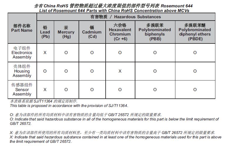
Figure 4-1: China RoHS Table
Quick Start Guide 47*00825-0200-4728*
Quick Start Guide
00825-0200-4728, Rev. HC
May 2019
Global Headquarters North America Regional Office
Emerson Automation Solutions Emerson Automation Solutions
6021 Innovation Blvd. 8200 Market Blvd.
Shakopee, MN 55379, USA Chanhassen, MN 55317, USA
+1 800 999 9307 or +1 952 906 8888 +1 800 999 9307 or +1 952 906 8888
+1 952 949 7001 +1 952 949 7001
RFQ.RMD-RCC@Emerson.com RMT-NA.RCCRF@Emerson.com
Latin America Regional Office Europe Regional Office
Emerson Automation Solutions Emerson Automation Solutions Europe
1300 Concord Terrace, Suite 400 GmbH
Sunrise, FL 33323, USA Neuhofstrasse 19a P.O. Box 1046
+1 954 846 5030 CH 6340 Baar
Switzerland
+1 954 846 5121
+41 (0) 41 768 6111
RFQ.RMD-RCC@Emerson.com
+41 (0) 41 768 6300
RFQ.RMD-RCC@Emerson.com
Asia Pacific Regional Office Middle East and Africa Regional Office
Emerson Automation Solutions Emerson Automation Solutions
1 Pandan Crescent Emerson FZE P.O. Box 17033
Singapore 128461 Jebel Ali Free Zone - South 2
+65 6777 8211 Dubai, United Arab Emirates
+65 6777 0947 +971 4 8118100
Enquiries@AP.Emerson.com +971 4 8865465
RFQ.RMTMEA@Emerson.com
©2019 Emerson. All rights reserved.
Linkedin.com/company/Emerson-
Automation-Solutions Emerson Terms and Conditions of Sale are
Twitter.com/Rosemount_News available upon request. The Emerson logo is a
trademark and service mark of Emerson Electric
Facebook.com/Rosemount
Co. Rosemount is mark of one of the Emerson
Youtube.com/user/ family of companies. All other marks are the
RosemountMeasurement property of their respective owners.You can also read