Inspecting assemblies - Publication Number - Siemens
←
→
Page content transcription
If your browser does not render page correctly, please read the page content below

Inspecting assemblies

      Publication Number
          spse01680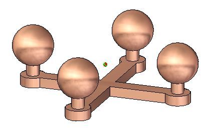
Inspecting assemblies

      Publication Number
          spse01680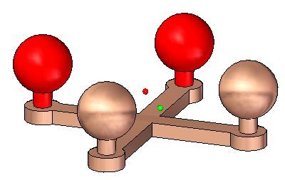
Proprietary and restricted rights notice

                  This software and related documentation are proprietary to Siemens Product
                  Lifecycle Management Software Inc.
                  © 2011 Siemens Product Lifecycle Management Software Inc. All Rights Reserved.
                  Siemens and the Siemens logo are registered trademarks of Siemens AG. Solid Edge
                  is a trademark or registered trademark of Siemens Product Lifecycle Management
                  Software Inc. or its subsidiaries in the United States and in other countries. All
                  other trademarks, registered trademarks or service marks belong to their respective
                  holders.

2   Inspecting assemblies                                                                   spse01680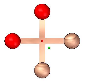
Contents

            Introduction . . . . . . . . . . . . . . . . . . . . . . . . . . . . . . . . . . . . . . . . . . . . . . 1-1

            Inspecting assemblies . . . . . . . . . . . . . . . . . . . . . . . . . . . . . . . . . . . . . . . 2-1

            Introduction . . . . . . . . . . . . . . . . . . . . . . . . . . . . . . . . . .                                                   .   .   .   .   .   .   .   .   .   .   .   .   .   .    2-2
            Objectives . . . . . . . . . . . . . . . . . . . . . . . . . . . . . . . . . . .                                                   .   .   .   .   .   .   .   .   .   .   .   .   .   .    2-3
            Physical properties of parts and assemblies . . . . . . . . . . . .                                                                .   .   .   .   .   .   .   .   .   .   .   .   .   .    2-4
            Activity: Computing mass properties of an assembly . . . . .                                                                       .   .   .   .   .   .   .   .   .   .   .   .   .   .    2-8
            Lesson review . . . . . . . . . . . . . . . . . . . . . . . . . . . . . . . . .                                                    .   .   .   .   .   .   .   .   .   .   .   .   .   .    2-9
            Answers . . . . . . . . . . . . . . . . . . . . . . . . . . . . . . . . . . . . .                                                  .   .   .   .   .   .   .   .   .   .   .   .   .   .   2-10
            Lesson summary . . . . . . . . . . . . . . . . . . . . . . . . . . . . . .                                                         .   .   .   .   .   .   .   .   .   .   .   .   .   .   2-11
            Analyzing movement and detecting collisions in assemblies                                                                          .   .   .   .   .   .   .   .   .   .   .   .   .   .   2-12
            Distance and area measurement . . . . . . . . . . . . . . . . . . .                                                                .   .   .   .   .   .   .   .   .   .   .   .   .   .   2-14
             Drag Component command . . . . . . . . . . . . . . . . . . . . . . .                                                              .   .   .   .   .   .   .   .   .   .   .   .   .   .   2-18
            Activity: Analyzing motion . . . . . . . . . . . . . . . . . . . . . . .                                                           .   .   .   .   .   .   .   .   .   .   .   .   .   .   2-19
            Lesson review . . . . . . . . . . . . . . . . . . . . . . . . . . . . . . . . .                                                    .   .   .   .   .   .   .   .   .   .   .   .   .   .   2-20
            Answers . . . . . . . . . . . . . . . . . . . . . . . . . . . . . . . . . . . . .                                                  .   .   .   .   .   .   .   .   .   .   .   .   .   .   2-21
            Lesson summary . . . . . . . . . . . . . . . . . . . . . . . . . . . . . .                                                         .   .   .   .   .   .   .   .   .   .   .   .   .   .   2-22
            Sensors . . . . . . . . . . . . . . . . . . . . . . . . . . . . . . . . . . . . .                                                  .   .   .   .   .   .   .   .   .   .   .   .   .   .   2-23
            Activity: Creating a sensor . . . . . . . . . . . . . . . . . . . . . . .                                                          .   .   .   .   .   .   .   .   .   .   .   .   .   .   2-26
            Lesson review . . . . . . . . . . . . . . . . . . . . . . . . . . . . . . . . .                                                    .   .   .   .   .   .   .   .   .   .   .   .   .   .   2-27
            Answers . . . . . . . . . . . . . . . . . . . . . . . . . . . . . . . . . . . . .                                                  .   .   .   .   .   .   .   .   .   .   .   .   .   .   2-28
            Lesson summary . . . . . . . . . . . . . . . . . . . . . . . . . . . . . .                                                         .   .   .   .   .   .   .   .   .   .   .   .   .   .   2-29
            Checking interference on parts . . . . . . . . . . . . . . . . . . . .                                                             .   .   .   .   .   .   .   .   .   .   .   .   .   .   2-30
            Activity: Interference checking . . . . . . . . . . . . . . . . . . . .                                                            .   .   .   .   .   .   .   .   .   .   .   .   .   .   2-32
            Lesson review . . . . . . . . . . . . . . . . . . . . . . . . . . . . . . . . .                                                    .   .   .   .   .   .   .   .   .   .   .   .   .   .   2-33
            Answers . . . . . . . . . . . . . . . . . . . . . . . . . . . . . . . . . . . . .                                                  .   .   .   .   .   .   .   .   .   .   .   .   .   .   2-34
            Lesson summary . . . . . . . . . . . . . . . . . . . . . . . . . . . . . .                                                         .   .   .   .   .   .   .   .   .   .   .   .   .   .   2-35

            Lesson review . . . . . . . . . . . . . . . . . . . . . . . . . . . . . . . . . . . . . . . . . . . . . 3-1

            Lesson summary . . . . . . . . . . . . . . . . . . . . . . . . . . . . . . . . . . . . . . . . . . . 4-1

            Activity: Computing mass properties of an assembly . . . . . . . . . . . . . . . A-1

            Open the assembly and change the material                                              .   .   .   .   .   .   .   .   .   .   .   .   .   .   .   .   .   .   .   .   .   .   .   .   . A-2
            Examine the physical properties . . . . . . . .                                        .   .   .   .   .   .   .   .   .   .   .   .   .   .   .   .   .   .   .   .   .   .   .   .   . A-4
            Change the material . . . . . . . . . . . . . . . . .                                  .   .   .   .   .   .   .   .   .   .   .   .   .   .   .   .   .   .   .   .   .   .   .   .   . A-7
            Activity Summary . . . . . . . . . . . . . . . . . . .                                 .   .   .   .   .   .   .   .   .   .   .   .   .   .   .   .   .   .   .   .   .   .   .   .    A-10

            Activity: Analyzing motion . . . . . . . . . . . . . . . . . . . . . . . . . . . . . . . . . . . B-1

            Open the assembly . . .          ...   .   .   .   .   .   .   .   .   .   .   .   .   .   .   .   .   .   .   .   .   .   .   .   .   .   .   .   .   .   .   .   .   .   .   .   .   . B-2
            Motion environment . .           ...   .   .   .   .   .   .   .   .   .   .   .   .   .   .   .   .   .   .   .   .   .   .   .   .   .   .   .   .   .   .   .   .   .   .   .   .   . B-3
            Find the initial collision        ..   .   .   .   .   .   .   .   .   .   .   .   .   .   .   .   .   .   .   .   .   .   .   .   .   .   .   .   .   .   .   .   .   .   .   .   .   . B-6
            Activity Summary . . . .         ...   .   .   .   .   .   .   .   .   .   .   .   .   .   .   .   .   .   .   .   .   .   .   .   .   .   .   .   .   .   .   .   .   .   .   .   .    B-11

spse01680                                                                                                                                              Inspecting assemblies                              3
Contents
Activity: Creating a sensor . . . . . . . . . . . . . . . . . . . . . . . . . . . . . . . . . . . C-1
Open the assembly with all parts active . . . . . . . . . . . . . . . . . . . . . . . . . . . . C-2
Reestablish the mate relationship . . . . . . . . . . . . . . . . . . . . . . . . . . . . . . . . C-3
Create sensor . . . . . . . . . . . . . . . . . . . . . . . . . . . . . . . . . . . . . . . . . . . . . . . C-4
Test the sensor . . . . . . . . . . . . . . . . . . . . . . . . . . . . . . . . . . . . . . . . . . . . . . C-6
Activity Summary . . . . . . . . . . . . . . . . . . . . . . . . . . . . . . . . . . . . . . . . . . . . C-8
Activity: Interference checking . . . . . . . . . . . . . . . . . . . . . . . . . . . . . . . D-1
Open the assembly and analyze the interference . . . . . . . . . . . . . . . . . . . . . . D-2
Find the interference . . . . . . . . . . . . . . . . . . . . . . . . . . . . . . . . . . . . . . . . . D-5
Measure the interference . . . . . . . . . . . . . . . . . . . . . . . . . . . . . . . . . . . . . . . D-6
Unlock the handle and reposition . . . . . . . . . . . . . . . . . . . . . . . . . . . . . . . . . D-9
Activity Summary . . . . . . . . . . . . . . . . . . . . . . . . . . . . . . . . . . . . . . . . . . . D-13
4 Inspecting assemblies spse01680Lesson
1 Introduction
Welcome to self paced training for Solid Edge. This course is designed to educate you
in the use of Solid Edge. The course is self-paced and contains instruction followed
by activities.
Solid Edge self-paced courses
• spse01510—Sketching
• spse01515—Constructing base features
• spse01520—Moving and rotating faces
• spse01525—Working with face relationships
• spse01530—Constructing treatment features
• spse01535—Constructing procedural features
• spse01536—Modeling synchronous and ordered features
• spse01540—Modeling assemblies
• spse01545—Creating detailed drawings
• spse01546—Sheet metal design
• spse01550—Practicing your skills with projects
• spse01560—Modeling a Part Using Surfaces
• spse01610—Solid Edge frame design
• spse01640—Assembly patterning
• spse01645—Assembly systems libraries
• spse01650—Working with large assemblies
• spse01655—Revising assemblies
• spse01660—Assembly reports
• spse01665—Replacing parts in an assembly
• spse01670—Designing in the context of an assembly
spse01680 Inspecting assemblies 1-1Lesson 1 Introduction
• spse01675—Assembly features
• spse01680—Inspecting assemblies
• spse01685—Alternate assemblies
• spse01686—Adjustable parts and assemblies
• spse01690—Virtual components in assemblies
• spse01691—Exploding assemblies
• spse01692—Rendering assemblies
• spse01693—Animating assemblies
• spse01695—XpresRoute (tubing)
• spse01696—Creating a Wire Harness with Harness Design
• spse01424—Working with Solid Edge Embedded Client
Start with the tutorials
Self-paced training begins where tutorials end. Tutorials are the quickest way for
you to become familiar with the basics of using Solid Edge. If you do not have any
experience with Solid Edge, please start by working through the tutorials for basic
part modeling and editing before starting this self-paced training.
1-2 Inspecting assemblies spse01680Lesson
2 Inspecting assemblies
spse01680 Inspecting assemblies 2-1Lesson 2 Inspecting assemblies
Introduction
Solid Edge supports a variety of tools to inspect and analyze assemblies. Covered
here are:
• Motion
• Collision detection
• Sensors
• Mass properties
2-2 Inspecting assemblies spse01680Inspecting assemblies
Objectives
After completing this lesson, you should be able to:
• Assign material densities to different parts and calculate a center of mass and
weight of an assembly.
• Use motion to analyze and detect collisions in unconstrained parts.
• Establish sensors to warn if an unconstrained part is violating a set parameter
as it moves.
spse01680 Inspecting assemblies 2-3Lesson 2 Inspecting assemblies
Physical properties of parts and assemblies
You can calculate the following physical properties of parts and assemblies:
• Volume
• Mass
• Center of volume
• Center of mass
• Surface area
• Orientation of the principal axis
• Mass moments of inertia
• Radii of gyration
Note
You can calculate surface area only for parts.
Center of mass, center of volume, mass moment of inertia, and principal axis
coordinates are output with respect to the global coordinate system. Principal
moments of inertia and radii of gyration are output with respect to the principal axes.
Physical property symbols
The Physical Properties command places symbols on the part or assembly to show
the center of mass location, center of volume location, and principal axis orientation.
You can display and hide the symbols individually, or display them all at once using
the Physical Properties dialog box.
Calculating and storing physical properties
When you calculate physical properties for a part, the Physical Properties command
calculates and stores the properties for the individual part. In the Assembly
2-4 Inspecting assemblies spse01680Inspecting assemblies
environment, the Physical Properties command calculates and stores the properties
for the entire assembly.
If you want to calculate the properties for a portion of an assembly, you can select the
individual parts in the assembly before selecting the command. The software places
property symbols indicating the center of mass, center of volume, and principal
directions for the selection set.
Physical properties for a selection set are not stored with the assembly. When you
close the Physical Properties dialog box, the property data for the entire assembly
is restored. To store physical properties of a selection set, click the Save As button
before dismissing the Physical Properties dialog box.
Using coordinate systems
You can calculate physical properties relative to a user-defined coordinate system.
A list of all user-defined coordinate systems plus an entry for the Model Space
coordinate system, which is the default, is available on the Physical Properties
dialog box. Calculating physical properties relative to a user-defined coordinate
system will affect all properties other than Mass, Volume, and Surface Area.
Defining the density
Before calculating the physical properties for a part or the weld beads in a weldment
assembly you must specify the density of the part or weld bead.
For a part, you can define the density on the Material tab of the Solid Edge Material
Table dialog box, the Physical Properties dialog box, or the Variable Table. The
Change button on the Physical Properties dialog box displays the Solid Edge Material
Table dialog box so you can edit the material type and/or the density for the part.
For weldment assemblies, you can define the weld bead material density using the
Weldment Assembly command, or the Variable Table.
When you have defined the density, click the Update button. You must provide a
positive density value. If you do not specify a density, Solid Edge uses a density of
zero and produces the error message: Density Must Be A Positive Numeric Value.
Note
You can create material-specific template files by defining the material and
density in the files you use as templates.
In the Assembly environment, the software checks each part in the assembly
to determine if a density was defined for each part in the Part or Sheet Metal
environments. If you have not specified a density for a particular part, you can
supply a density value for calculating the part’s physical properties.
When you save an assembly, part, or sheet metal document, you can also save the
density information with the document. The information can be used later to update
the physical properties.
User-defined properties
You can override physical properties calculated by the software by setting the User
Defined Properties option on the Physical Properties dialog box in the Part and
Sheet Metal environments. For example, if you know the mass for a particular part,
spse01680 Inspecting assemblies 2-5Lesson 2 Inspecting assemblies
you can supply the value, and it will be treated as computed data. However, if you
then update values, the software will recalculate and override any user-defined
values. The physical properties will not update using a mix of user-defined and
system calculated properties.
Note
Density, Mass, and Volume cannot be zero.
Failed parts or assemblies
Physical properties cannot be calculated for parts with features that have not
recalculated correctly. In the Part and Sheet Metal environments, you can use the
Error Assistant dialog box to determine which parts have features that have not
recalculated correctly and why.
Updating physical properties
If you change a part or assembly so that its physical properties change, the colors
of the physical properties symbols change to show that the last calculated physical
properties are out-of-date and should be updated. For example, if you change the
material density for a part, the physical properties symbols can go out of date.
A part can also become out-of-date if you add, delete, or modify a feature. An
assembly can become out-of-date if you add or delete a part from the assembly, or if
you add or remove assembly features.
In the Part and Sheet Metal environments, you can set or clear the Update on File
Save option to specify whether the physical properties are automatically updated
when you save the document. You can also update the physical properties of a part
or assembly by selecting the Update button on the Physical Properties dialog box.
A message is displayed at the bottom of the dialog box that indicates whether the
physical properties are up-to-date or out-of-date.
Physical properties manager
In the Assembly environment, you can use the Physical Properties Manager
command to view, edit, and manage the physical properties for all the parts in the
active assembly. This can be useful because you can view and edit the physical
properties for all the parts at once, rather opening each part document to view and
edit its physical properties.
2-6 Inspecting assemblies spse01680Inspecting assemblies
Mapping physical properties for synchronization with Teamcenter
By using mapping definition files, physical properties such as density, mass, and
volume can be stored in the Teamcenter database and displayed and modified
in both Solid Edge and Teamcenter. This synchronization allows an attribute in
one application to be updated automatically when a modification is made to the
corresponding attribute in another application. Refer to the Sold Edge Embedded
Client Administrator’s Guide, for attribute mapping syntax and examples.
spse01680 Inspecting assemblies 2-7Lesson 2 Inspecting assemblies
Activity: Computing mass properties of an assembly
Overview
This activity shows how to change materials, and how to compute mass
properties and center of gravity of an assembly.
Turn to Appendix A for the activity.
2-8 Inspecting assemblies spse01680Inspecting assemblies
Lesson review
Answer the following questions:
1. In a part or sheet metal document, how is the density of the material defined?
2. In an assembly document, how is the density of the material defined?
3. Where is the radii of gyration calculated and the values displayed in an assembly
document?
spse01680 Inspecting assemblies 2-9Lesson 2 Inspecting assemblies
Answers
1. In a part or sheet metal document, how is the density of the material defined?
The material table allows you to define the material and density of a part or
sheet metal document.
2. In an assembly document, how is the density of the material defined?
The properties manager shows and allows edits to the material properties for
the all the assembly components.
3. Where is the radii of gyration calculated and the values displayed in an assembly
document?
The radii of gyration is calculated and displayed on the principal tab of the
physical properties dialog box.
2-10 Inspecting assemblies spse01680Inspecting assemblies
Lesson summary
In this lesson you learned out to change the material of a part using the Physical
Property Manager, and how to calculate the mass properties for an assembly.
spse01680 Inspecting assemblies 2-11Lesson 2 Inspecting assemblies
Analyzing movement and detecting collisions in assemblies
You can use the Drag Component command in the Assembly environment to analyze
physical motion and detect collisions between parts in an assembly.
The Options button on the Drag Component command bar displays the Analyze
Options dialog box so you can define the analysis options you want to use. To reduce
the performance impact when working with large assemblies, you should limit the
analysis to as few parts as possible.
The Analyze (Shown Parts Only) options allow you to specify whether only active
parts or both active and inactive parts are analyzed. With large assemblies, you can
activate only the parts you want to analyze, which can improve performance. You
can also hide the parts you do not want to analyze. These options are used when you
set the Physical Motion option on the command bar.
The Collision Options settings allow you to specify whether only the parts that
contact the selected part are analyzed or that all parts that move in tandem with
the selected part are analyzed. These options are used when you set the Detect
Collisions option on the command bar.
Analyzing motion
The Physical Motion option on the command bar allows you to simulate motion
in an assembly. This option detects contact between parts and applies temporary
constraints between the contacting parts to simulate motion. When you set this
option, you must select a part and define a movement type and value. Also with
this option, the Distance and Angle values you specify are applied incrementally,
rather than all at once. This makes it possible to analyze motion in mechanisms that
contain gears and other forms of sliding or intermittent contact.
2-12 Inspecting assemblies spse01680Inspecting assemblies
Collision detection
The Detect Collisions option on the command bar allows you to detect collisions
between parts. You perform collision detection by dragging a part to simulate its
movement in the assembly. The part you are dragging must be free to move in the
assembly or be grounded. You can only select grounded parts and subassemblies
when the Locate Grounded Components option on the Analysis Options dialog box
is set.
If the part is not free to move, you can use the Suppress command on the shortcut
menu to temporarily suppress one or more of its assembly relationships. When
collisions are detected, the display changes to temporarily highlight the faces that
are involved in the collision. You can also specify that the part you are dragging
stops temporarily at the point of collision or that an audible warning is given.
If you are working in a shaded view, and a hidden face is involved in a collision, you
will not be able to see the hidden face highlight. To see these faces highlight, set
the view to Vector Hidden Line.
Note
The current zoom level impacts the accuracy of collision detection. For more
accurate results, zoom in closer to the area where collisions are suspected.
spse01680 Inspecting assemblies 2-13Lesson 2 Inspecting assemblies
Distance and area measurement
You can measure distances or areas, even when you are in the middle of another
task. To set the units for measuring distances or areas, use the Properties command
on the Application menu.
Measuring distances in 2D
In the Draft environment, you can measure distance using the Measure Distance
command. These commands measure linear distances or measure the cumulative
linear distance along a series of points. The first point you click establishes the origin
of the measurement (A). After that, you can select any keypoint to see the distance
between it and the origin, as well as the delta distance along each principal axis (B).
Clicking the keypoint adds it to a series of measurement points. Then you can select
another point to see the new linear distance and deltas (C), or click it to see the
distance between the last two points and the total cumulative distance from the
origin to the last point (D). Click the right button to reset the command.
2-14 Inspecting assemblies spse01680Inspecting assemblies
Measuring distances and angles in 3D
In the Part, Sheet Metal, and Assembly environments, the Measure Distance
command measures linear distances. The first point you click establishes the origin
of the measurement (A). After that, you can select any keypoint (B) to display the
Measure Distance dialog box which displays the keypoint select type, the true
distance, the apparent screen view distance, and the delta distance along each
principal axis.
In the Part, Sheet Metal, and Assembly environments, the Measure Angle command
measures angles. You can measure between any two faces or between any three
points.
Measuring minimum distances
In the Part, Sheet Metal, and Assembly environments, you can use the Measure
Minimum Distance command to measure the minimum distance between any two
elements or keypoints. You can use the Select Type option on the Minimum Distance
command bar to filter which type of elements you want to select. When working in
the context of an assembly, you can also use the Activate Part option to activate
the parts you want to measure.
spse01680 Inspecting assemblies 2-15Lesson 2 Inspecting assemblies
Measuring normal distances
In the Part, Sheet Metal, and Assembly environments, the Measure Normal
Distance command measures normal distances between a planar element or line and
a keypoint. You can use the Element Types option on the Measure Normal Distance
command bar to filter which type of elements you want to select. You can use the
Key Point option to specify the type of keypoint you want to identify when measuring
the distance. You can use the Coordinate System option to select a user-defined
coordinate system to define one of the points. If you use a coordinate system, the
returned values will be relative to the specified coordinate system. When working
in the context of an assembly, you can also use the Activate Part option to activate
the parts you want to measure.
Measuring areas
The Measure Area command, available only in the Draft environment and in 2D
profiles and sketches, measures the area inside a closed boundary (A). You can also
measure the cumulative area inside more than one closed boundary by holding the
Shift key as you click elements (B). Each time you click, the area of the last element
is displayed, along with the total area. Click another element without holding the
Shift key to reset the command.
Measuring lengths
The Measure Total Length command measures the cumulative length of a select
set of 2D geometry.
Measuring automatically
In addition to the individual distance, area, length, and angle commands, you
can use the Smart Measure command in 2D and 3D environments to measure
automatically based on what you select:
• Select a single 2D element or 3D object to measure its length or its angle or
radius.
• Select two or more 2D elements or 3D objects to measure the distance or angle
between them.
The Smart Measure command works like the Smart Dimension command, except
that it does not place a dimension as a result.
2-16 Inspecting assemblies spse01680Inspecting assemblies
Copying measurement values
You can copy the highlighted measurement value to the Clipboard by pressing
Ctrl+C. You can then use the copied value as input for another command. For
example, you can paste the copied value into the Line command bar to define the
length of a line. Use the Tab key if you want to highlight a different value.
Measuring drawing view geometry
When you measure model geometry within a drawing view, or when you measure
distances between model edges in two drawing views, you can select the Use
Drawing View Scale check box on the command bar to specify that the measured
value is displayed using the equivalent of the model distance.
Alternatively, you can apply a user-defined scale value by selecting it from the Scale
list on the command bar.
Note
• You can show the scale of a drawing view using the General page (Drawing
View Properties dialog box).
• User-defined scale values are defined in the Drawing View Scales section
of the Custom.xml file, in the Solid Edge Program folder. See the Help
topic, Add custom drawing view scales to Solid Edge.
spse01680 Inspecting assemblies 2-17Lesson 2 Inspecting assemblies
Drag Component command
Translates or rotates parts in an assembly. The part being moved must be grounded
or not fully positioned. You can use this command to do the following:
• Reposition parts dynamically along the x, y, or z axis.
• Analyze physical motion in mechanisms.
• Detect collisions between parts.
Any relationships applied to the part will prevent movement along the axis
whose position is controlled by a relationship. A part will move only in an
under-constrained direction. You can use the Suppress command on the shortcut
menu to temporarily suppress one or more assembly relationships to allow the part
to move.
You can only select grounded parts and subassemblies when the Locate Grounded
Components option on the Analysis Options dialog box is set.
After you select the part you want to move, you can use the options on the command
bar to specify the type of movement you want. For example, you can click the Move
button, then position the cursor over one of the principal axes and drag the part
to a new position.
You can restart the command by clicking the right mouse button.
Note
Patterned parts do not participate in collision detection or motion analysis.
When you use the Drag Component command to move an adjustable part, the
assembly relationships positioning the adjustable part are temporarily suppressed.
When you complete a move cycle, the relationships are reapplied. If the movement
you define conflicts with the adjustable part’s relationship structure, the adjustable
part is returned to its original position or a position that is consistent with the
relationship structure.
2-18 Inspecting assemblies spse01680Inspecting assemblies
Activity: Analyzing motion
Overview
This activity shows how to use motion to analyze collisions in moving parts.
Turn to Appendix B for the activity.
spse01680 Inspecting assemblies 2-19Lesson 2 Inspecting assemblies
Lesson review
Answer the following questions:
1. What is Simply motion?
2. How can you detect the initial point of a collision between moving parts?
3. Once an interference is detected how can the range of motion be limited so that
interference does not occur?
2-20 Inspecting assemblies spse01680Inspecting assemblies
Answers
1. What is Simply motion?
The Simply Motion module allows you to perform motion simulations on Solid
Edge assemblies. Simply Motion creates moving parts and motion joints directly
from assembly constraints. Additional joints, springs, and motion generators
can be added through an easy to use "Wizard" style interface. Simply Motion
contains a 3D dynamic motion engine that allows you to simulate problems that
are far beyond simple linkages or kinematic type problems. The simulation
results can be used to generate animations of your moving assembly, or to check
for interference as the assembly moves through its full range of simulated motion
Simply Motion is a subset of Dynamic Designer from Design Simulation
Technologies. Simply Motion is included in Solid Edge at no charge. Upgrades to
Dynamic Designer can be purchased from Design Simulation Technologies.
2. How can you detect the initial point of a collision between moving parts?
Using the interference tab in Simply motion will analyze and show where
the initial interference occurs. The drag component command also checks for
collisions and interference.
3. Once an interference is detected how can the range of motion be limited so that
interference does not occur?
The range offset values can be set for valid assembly relationships.
spse01680 Inspecting assemblies 2-21Lesson 2 Inspecting assemblies
Lesson summary
In this lesson you learned how to use the Motion command to analyze the movement
of a simple linkage. Parts that did not move were grounded and parts that did
move had no constraints in the their direction of travel. When motion was applied,
interference was detected and measured.
2-22 Inspecting assemblies spse01680Inspecting assemblies
Sensors
When constructing parts and assemblies, you often need to keep track of critical
design parameters. For example, when designing a shield or shroud that encloses a
rotating part, you must maintain enough clearance for maintenance and operational
purposes. You can use the Sensors tab on PathFinder to define and keep track
of design parameters for your parts and assemblies.
You can define the following types of sensors:
• Minimum distance sensors
• General variable sensors
• Sheet metal sensors
• Surface area sensors
• Custom sensors
Creating a sensor
Although there are several types of sensors, you follow the same basic steps when
creating any sensor:
1. From the Sensors tab on PathFinder, select the sensor type you want.
2. Define what you want to track in the design.
3. Define the operating limits for the sensor.
Every sensor you define in the document is displayed and managed on the Sensors
tab on PathFinder.
Minimum distance sensors
Minimum distance sensors are used to track the minimum distance between any two
elements. For example, you can track the minimum distance between two part faces
in an assembly. You define a minimum distance sensor similar to how you measure
the minimum distance between two elements with the Minimum Distance command.
When you click the Minimum Distance Sensor button on the Sensors tab, the
Minimum Distance command bar is displayed so you can select the two elements
you want to measure between. After you select the two measurement elements, the
Measure Distance box displays the current minimum distance value. When you click
the Close button on the command bar, the Minimum Distance Sensor Parameters
dialog box is displayed so you can define the sensor parameters you want, such as
the sensor name, display type, threshold value, sensor range, and so forth. When
you click OK, the new sensor is displayed on the Sensors tab.
General variable sensors
You can use a general variable sensor to track variables, such as driving and driven
dimensions. To create a general variable sensor, select the Variable Sensor button
on the Sensors tab, then select the variable you want in the variable table. When
spse01680 Inspecting assemblies 2-23Lesson 2 Inspecting assemblies
you click the Add Variable button on the Variable Sensor Parameters dialog box, the
variable value is added to the Current Value box. You can then define the remaining
sensor parameters.
Sheet metal sensors
You can use sheet metal sensors to track design parameters, such as the minimum
distance between particular types of sheet metal features and part edges. You can
create your own sheet metal sensors from scratch, or you can select from a list of
predefined examples.
Sheet metal sensors are available only in sheet metal documents.
To create a sheet metal sensor, select the Sheet Metal Sensor button on the Sensors
tab, then use the Sheet Metal Sensor command bar to define the faces and edge
sets you want to track. When you click the Finish button, the Sheet Metal Sensor
Parameters dialog box displays so you can define the remaining sensor parameters.
Note
Sheet metal sensors are not available in 64-bit systems.
Surface area sensors
You can use a surface area sensor to monitor a surface or a set of surfaces. You can
monitor both positive and negative surface area. A negative surface area sensor
monitors the "holes" or internal boundaries in a surface. For example, you may need
to track the total area for a series of ventilation holes and cutouts in a surface.
The Surface Area Sensor command bar is where you define the faces you want to
track as a sensor. When you click the Accept (checkmark) button on the command
bar, the Surface Area Sensor Parameters dialog box displays so you can define the
remaining sensor parameters. This sensor type is available only for part and sheet
metal documents.
Custom sensors
You can use a custom sensor to monitor any numeric result that is calculated from a
custom program. For example, you could create a custom program that assigns a
manufacturing cost to each feature type used for creating sheet metal parts. The
program would then monitor the part features and give you the part cost of the
completed model.
When you click the Custom Sensor button, it displays the Custom Sensor DLL dialog
box so you can define the DLL and user function you want. After you define the DLL
and user function, and click OK, the Custom Sensor Parameters dialog box displays
so you can define the sensor parameters.
Note
For more in-depth information on how to use custom sensors, see the
readme.doc file delivered to the Solid Edge\Custom\CustomSensor folder.
2-24 Inspecting assemblies spse01680Inspecting assemblies
Sensor alarms
When a change to the model exceeds the defined sensor threshold limit, the Sensors
tab displays a special notification symbol and a sensor violation alarm is displayed
in the upper-right corner of the graphic window.
Violation alarms
On the Sensors tab:
In the graphics window:
When one of the elements a sensor tracks is deleted, a warning notification symbol is
displayed to call attention to it.
Warning alarms
On the Sensors tab:
In the graphics window:
When you see an alarm symbol in the upper-right corner of the graphics window,
you can click it to respond to the alarm. This displays the Sensor Assistant, which
contains hyperlinks to all the sensor violations and warnings in the document.
You can activate or deactivate the Sensor Assistant and alarm notification in the
graphics window using the Show Sensor Indicator option on the Helpers page of the
Solid Edge Options dialog box. This does not affect the operation of the sensors
themselves.
To learn how to use the Sensor Assistant, see Responding to sensor alarms.
spse01680 Inspecting assemblies 2-25Lesson 2 Inspecting assemblies
Activity: Creating a sensor
Overview
When you complete this activity, you will be able to create a distance sensor to
track the motion of a simple bar linkage.
Turn to Appendix C for the activity.
2-26 Inspecting assemblies spse01680Inspecting assemblies
Lesson review
Answer the following questions:
1. Name three types of sensors.
2. Is the interface for sensors a tab in pathfinder?
3. How can you tell when a sensor has been violated?
spse01680 Inspecting assemblies 2-27Lesson 2 Inspecting assemblies
Answers
1. Name three types of sensors.
The types of sensors are:
a. Minimum distance sensor
b. General variable sensors
c. Surface area sensors
Custom sensors and sheet metal specific sensors can also be created.
2. Is the interface for sensors a tab in pathfinder?
The sensors tab is located in pathfinder?
3. How can you tell when a sensor has been violated?
An attention icon will display. It must be turned on in Solid Edge
Options>Helpers tab.
2-28 Inspecting assemblies spse01680Inspecting assemblies
Lesson summary
In this lesson you learned how to create a distance sensor and establish a valid range
of travel. Parameters on the distance sensor were set so that when the travel of the
mechanism passed the valid range, alerts were triggered.
spse01680 Inspecting assemblies 2-29Lesson 2 Inspecting assemblies
Checking interference on parts
Solid Edge allows you to check for interference between parts in assemblies using
the Check Interference command on the Inspect tab.
Creating sets of parts
To run an interference analysis, you must create one or two sets of parts. A set of
parts typically contains many parts; however, each set can contain any number of
parts. If a set of parts will include all the parts in a subassembly, you can select
the subassembly using the PathFinder.
Note
You can also use the Select Tools tab on PathFinder to define a select set
using a query.
Checking sets of parts for interference
You can check parts in the following ways during the interference analysis:
• All parts of set one against all parts of set two.
• All parts of set one against all other parts in the active assembly.
• All parts of set one against all currently displayed parts.
• All parts of set one against themselves.
Unless you indicate otherwise, the software uses the first option, checking all the
parts of set one against all the parts of set two.
2-30 Inspecting assemblies spse01680Inspecting assemblies
Interference and threaded features
You can use the settings on the Options Tab (Interference Options dialog box) to
control how threaded fastener interference is checked.
Check interference can report or ignore interferences when the threaded portion
of a bolt interferes with a non-threaded hole in a mating part. For example, you
would typically want to ignore interferences when using a self-tapping bolt in a
non-threaded hole, but would want to report interferences when a standard bolt
extends past the thread depth in a threaded mating part.
The Ignore Threaded Fasteners Interfering With Non-threaded Holes option allows
you to control whether interference is detected in these situations.
Check interference also can report or ignore interferences between a threaded
cylinder and a threaded hole whose nominal diameters match. When you set the
Ignore Interferences of the Same Nominal Diameter option, if the thread pitch does
not match between a bolt and a threaded hole with the same nominal diameters, no
interference is detected.
Analyzing results
Before running the interference analysis, you can set options for analyzing results.
The following methods are available:
• Output a report to a text file.
• Display the interfering volumes.
• Save the interfering volumes as parts.
• Highlight the interfering parts.
• Dim the display of parts that do not interfere.
• Hide parts not selected for an interference check.
If no interferences were detected during the interference analysis, the software
displays a message box telling you that no interferences were detected.
spse01680 Inspecting assemblies 2-31Lesson 2 Inspecting assemblies
Activity: Interference checking
Overview
In this activity, you learn how to:
• Use the interference checking and measure tools to determine where parts
interfere with each other.
• Edit the part shape to correct the offending part.
• Edit part relationships.
Turn to Appendix D for the activity.
2-32 Inspecting assemblies spse01680Inspecting assemblies
Lesson review
Answer the following questions:
1. After selecting a set of assembly components to check for interference, what
options are available to perform the interference detection?
2. After the interference is detected, what options exist for analyzing the
interference?
spse01680 Inspecting assemblies 2-33Lesson 2 Inspecting assemblies
Answers
1. After selecting a set of assembly components to check for interference, what
options are available to perform the interference detection?
The options are:
a. Select set 2
b. All other parts in the assembly
c. Parts currently shown
d. Itself
2. After the interference is detected, what options exist for analyzing the
interference?
The options are:
a. Generate Report
b. Create interfering volumes and show them or save them as a part.
c. Hide parts not in the select sets
d. Highlight interfering parts
e. Dim parts with no interference
f. Hide parts with no interference
g. Ignore interference between matching threads
h. Ignore threaded fasteners interfering with non-threaded holes
2-34 Inspecting assemblies spse01680Inspecting assemblies
Lesson summary
In this lesson you learned how to check for interference between parts and
subassemblies. You learned how to determine the extent of the interference and
make the modifications necessary to correct the interference.
spse01680 Inspecting assemblies 2-35Lesson
3 Lesson review
1. What do the check interference options control?
2. Where are motion tools located in Solid Edge assembly?
3. When setting up the assembly for motion, which command steps you through the
motion process?
4. What are the two types of sensors available in the assembly ?
5. Describe the difference between true/false range and horizontal range sensors.
spse01680 Inspecting assemblies 3-1Lesson
4 Lesson summary
• When creating an assembly, at some point you must test the design to see if it is
valid. Solid Edge provides tools to calculate physical properties, analyze part
motion, and check for minimum distance. Using these tools, you can quickly
identify potential problem areas and correct your design.
• The physical properties dialog box, located under the inspect tab, activates
graphics in the assembly view to illustrate physical properties.
• The motion commands in Solid Edge assembly set parts in motion so you can
analyze the motion and check for part interference. Motion is found under the
tools tab.
• Sensors help monitor critical design elements in assembly design applications
where parts must maintain a minimal clearance from others. Sensors can
monitor required conditions and warn when a condition is not met. The sensors
tab is located on PathFinder.
• Interference can be checked against a subset of parts or the whole of the
assembly. A part file representing the common volume defining the interference
can be produced to see the shape of the interference, and to measure overlapping
volumes in order to fix the problem.
spse01680 Inspecting assemblies 4-1A Activity: Computing mass
properties of an assembly
Overview
When you complete this activity, you will be able to change material types in parts,
and then compute the center of mass in an assembly.
Objectives
The activity consists of the following:
• Editing a part in the context of an assembly.
• Changing the materials for each part.
• Computing the mass properties for the assembly.
Activity
spse01680 Inspecting assemblies A-1A Activity: Computing mass properties of an assembly
Open the assembly and change the material
▸ Open and activate all the parts in the assembly mass.asm located in the folder
where the activity files are located.
Note
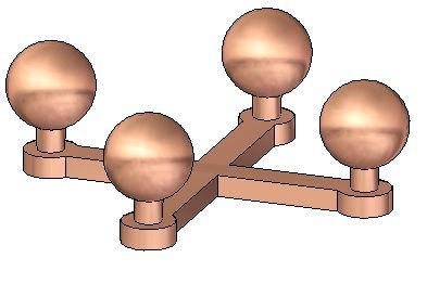
The assembly consists of five parts: the base and the four posts with spheres.
If the posts were identical, the assembly could have been made with just two
parts, and the post placed four times. In this activity, the posts are different
because the material and density will be altered for each post.
▸ Choose the Inspect tab→Physical Properties group→Properties Manager
command .
A-2 Inspecting assemblies spse01680Activity: Computing mass properties of an assembly
▸ In the dialog box, set the material for all the parts to be copper, and then click
Update All.
Note
Another way to change the material for each of the posts is to in-place activate
and change the material through File Properties→Material Table. With the
Physical Properties Manager, this task is much simpler.
▸ Notice the color of the parts have changed to match the material. Click OK to
dismiss the dialog box.
spse01680 Inspecting assemblies A-3A Activity: Computing mass properties of an assembly
Examine the physical properties
Since the whole assembly is symmetric about the front and right planes, you would
expect the center of gravity to be centered in the top view.
▸ Choose the Inspect tab→Physical Properties group→Properties
command .
▸ Turn on the Display Symbol for the center of mass and the center of volume.
Notice that the mass is 1.74 kilograms. Click Update, and then click Close.
A-4 Inspecting assemblies spse01680Activity: Computing mass properties of an assembly
Note
Rotate the view and notice that the center of mass and the center of
volume are located in the same position. The center of volume should not
change for this assembly for the remainder of the activity. The center
of mass will change.
▸ Choose the Inspect tab→Physical Properties group→Properties
command .
spse01680 Inspecting assemblies A-5A Activity: Computing mass properties of an assembly
▸ Click the Principal tab to calculate the principal axes. Turn on the Display
Symbol for the principal axes. Click Update, and then click Close.
A-6 Inspecting assemblies spse01680Activity: Computing mass properties of an assembly
Change the material
▸ Choose the Inspect tab→Physical Properties group→Properties Manager
command .
▸ In the dialog box, set the material for all the parts as shown, and then click
Update All. Click OK to dismiss the dialog box.
Note
Notice that Polycarbonate is much less dense than copper. This means the
center of gravity will be closer to the two copper posts.
▸ Choose the Inspect tab→Physical Properties group→Properties
command .
spse01680 Inspecting assemblies A-7A Activity: Computing mass properties of an assembly
▸ Click the Principal tab to calculate the principal axes. Turn off the display
symbol for the principal axes. Click Update, and then click Close.
A-8 Inspecting assemblies spse01680Activity: Computing mass properties of an assembly
▸ Rotate the view to the top and observe the location of the center of mass.
▸ Continue using the Physical Properties Manager. Change the material values of
the parts in the assembly and observe how the mass and center of gravity change.
▸ Save and close the assembly. This completes this activity.
spse01680 Inspecting assemblies A-9A Activity: Computing mass properties of an assembly
Activity Summary
In this activity you learned out to change the material of a part using the Physical
Property Manager, and how to calculate the mass properties for an assembly.
A-10 Inspecting assemblies spse01680B Activity: Analyzing motion
Overview
This activity shows how to use the Motion command to analyze collisions in moving
parts.
Objectives
You will use the Motion command to analyze the motion of a simple bar linkage.
Activity
spse01680 Inspecting assemblies B-1B Activity: Analyzing motion
Open the assembly
Open the assembly and activate all the parts in the assembly.
▸ Open and activate all the parts in the assembly slider_linkage.asm located in the
folder where the activity files are located.
▸ In Assembly PathFinder, select slider_block.par. Right-click the mate
relationship, and click Delete Relationship.
B-2 Inspecting assemblies spse01680Activity: Analyzing motion
Motion environment
Start the Motion application.
▸ Choose the Tools tab→Environs group→Motion command .
▸ When prompted to automatically add the parts, click No in the dialog box.
▸ In the Motion environment, in the Settings group, select the Display Motion
Builder command .
spse01680 Inspecting assemblies B-3B Activity: Analyzing motion
▸ In the Motion Builder wizard, click the Gravity tab. Verify the Gravity On box is
selected, and then click Next.
▸ On the Parts tab, drag base block.par;1, rod_a.par;1, and pin.par:1 to Ground
Parts.
B-4 Inspecting assemblies spse01680Activity: Analyzing motion
▸ Drag the remaining parts to Moving Parts. Dismiss the Simply Motion Messages
dialog box.
▸ Click Next to proceed to the Joints tab.
▸ Click the Joints plus sign to expand the joints list.
Note
Because you deleted the mate relationship before activating the motion
command, Solid Edge did not recognize or create a joint from the mate
relationship.
spse01680 Inspecting assemblies B-5B Activity: Analyzing motion
Find the initial collision
Simulate motion of the linkage and find the initial collision of the parts.
▸ In the Motion Builder wizard, click the Simulation tab.
▸ Click Simulate to set the parts in motion, and watch the motion display.
▸ Click the Interferences tab.
B-6 Inspecting assemblies spse01680Activity: Analyzing motion
▸ If the wizard blocks the view of the assembly, drag the wizard window to the
right of the assembly window. Click Check Interferences.
spse01680 Inspecting assemblies B-7B Activity: Analyzing motion
▸ In the assembly graphics window, click brace.par and slide_lever.par to add them
to the list of parts to test in the Find Interferences Over Time dialog box.
▸ Click the Options tab. Click Find First Contact, and then click Find Now.
B-8 Inspecting assemblies spse01680Activity: Analyzing motion
▸ Watch the assembly move and then stop when the first interference between the
two parts is detected.
Note
Part interference begins at frame 5.45257.
▸ Close the Find First Contact dialog box.
▸ On the Inspect tab, click Measure Distance. Set the element type to All elements.
▸ For the points to measure between, select the lower-right corner of the base and
the upper-right corner of the slider block.
spse01680 Inspecting assemblies B-9B Activity: Analyzing motion
▸ Notice that the distance in delta Z is -110.14 mm. These parts interfere if the
distance between the base block and the slider block is 110.14 mm or greater.
▸ On the Measure command bar, click Close.
▸ Close any open dialog boxes. Click Close and Return to return to the assembly.
▸ Save and close the file. This completes the activity.
B-10 Inspecting assemblies spse01680Activity: Analyzing motion
Activity Summary
In this activity you learned how to use the Motion command to analyze the
movement of a simple linkage. Parts that did not move were grounded and parts
that did move had no constraints in the their direction of travel. When motion was
applied, interference was detected and measured.
spse01680 Inspecting assemblies B-11C Activity: Creating a sensor
Objectives
When you complete this activity, you will be able to create a distance sensor to track
the motion of a simple bar linkage.
Activity
spse01680 Inspecting assemblies C-1C Activity: Creating a sensor
Open the assembly with all parts active
Open the assembly and activate all the parts in the assembly.
▸ Open and activate all the parts in the assembly slider_linkage.asm located in the
folder where the activity files are located.
C-2 Inspecting assemblies spse01680Activity: Creating a sensor
Reestablish the mate relationship
Reestablish the previously deleted mate relationship.
▸ In Assembly PathFinder, select slider_block.par and then click Edit Definition
.
▸ For the next relationship, create a mate relationship with an 80 mm offset value
between the top of the slider block and the bottom of the base block.
spse01680 Inspecting assemblies C-3C Activity: Creating a sensor
Create sensor
Create sensors.
▸ In PathFinder, click the Sensors tab .
▸ Click the Minimum Distance Sensor .
▸ From the Element Types list, select Surfaces.
▸ To measure between the top of the slider block and the bottom of the base block,
select the two surfaces.
▸ Click Close.
C-4 Inspecting assemblies spse01680Activity: Creating a sensor
▸ In the Sensor Parameters dialog box, enter the information as shown, and click
OK. In the previous activity, when interference was found using the Motion
command, the software determined a threshold value of 110.14. Click OK.
Note
Notice that the sensor is added to PathFinder.
spse01680 Inspecting assemblies C-5C Activity: Creating a sensor
Test the sensor
▸ In Assembly PathFinder, click slider block.par, and then click the mate
relationship with the 80 mm offset in the lower pane of Assembly PathFinder.
▸ Edit the slider block offset value to 118 mm.
▸ In PathFinder, click the Sensors tab.
Note
Notice that the sensor shows the range is no longer valid.
Note
When a sensor is violated, an icon appears on the upper right corner of the
screen.
C-6 Inspecting assemblies spse01680Activity: Creating a sensor
▸ Click the icon in the corner. Information is displayed. Click for more information.
The sensors document in PathFinder is displayed.
▸ Set the offset value of the slider block back to 50.00 mm. Notice that the sensor
returns to a valid state.
spse01680 Inspecting assemblies C-7C Activity: Creating a sensor
Activity Summary
In this activity you learned how to create a distance sensor and establish a valid
range of travel. Parameters on the distance sensor were set so that when the travel
of the mechanism passed the valid range, alerts were triggered.
C-8 Inspecting assemblies spse01680D Activity: Interference checking
Overview
When you complete this activity, you will know how to use the interference checking
and measure tools to determine where parts interfere with each other, how to edit
the part shape to correct the offending part, and how to edit part relationships.
Objectives
The activity consists of the following:
• Inspecting parts and subassemblies to determine interference and to measure
distances required to correct the interference.
• Editing parts in the context of the assembly to correct the interference.
Activity
spse01680 Inspecting assemblies D-1D Activity: Interference checking
Open the assembly and analyze the interference
Open an assembly and check for interference between adjacent parts. Once the
interference is found, the volume representing the interference is created as surface
features.
▸ Open and activate all the parts in the assembly ball_valve.asm located in the
folder where the activity files are located.
▸ Choose the Inspect tab→Evaluate group→Interference command .
▸ Click Interference Options.
D-2 Inspecting assemblies spse01680Activity: Interference checking
▸ On the Options tab, set the options as shown and click OK.
▸ Select the subassembly handle and ball.asm in PathFinder. Accept the selection.
▸ Click Process.
Note
A new part is placed at the bottom of the list in PathFinder. This part
represents the volume of the interference. The interference is represented
as a construction surface. Right-click the new part and ensure that
spse01680 Inspecting assemblies D-3D Activity: Interference checking
the construction surfaces are displayed by selecting Show Construction
Surfaces.
▸ Click the Select tool, and then select the interference part to highlight the
interference volume in the assembly window.
D-4 Inspecting assemblies spse01680Activity: Interference checking
Find the interference
The highlighted interference is between the ball and the end caps. Modify the end
cap to remove the interference.
▸ Shade the assembly using the Visible and Hidden Edges command .
▸ Press Ctrl+R on the keyboard to rotate the assembly to a right view. Use the
Zoom Area command for a better view of the interference.
spse01680 Inspecting assemblies D-5D Activity: Interference checking
Measure the interference
Measure the elements to help decide how to modify one of the parts.
▸ Right-click Interference1.par in PathFinder and choose Show Only.
▸ Choose the Inspect tab→3D Measure group→Inquire Element command .
▸ Select the outside radius of the ball.
▸ Notice the radius is 30 mm. Remember this value when the end cap is modified.
▸ Right-click valve_endcap.par:2 in PathFinder and choose Show.
▸ Choose the Inspect tab→3D Measure group→Measure Distance command.
Using keypoints, measure from the radius of the ball to the midpoint on the
mating surface of the end cap. To select the center of the sphere, select the
circular edge shown, then select the face of the end cap shown.
▸ Notice the distance value is 35 mm. Remember this value when editing the end
cap. Click Close to exit the measuring command.
D-6 Inspecting assemblies spse01680Activity: Interference checking
▸ Click the Select tool command, right-click the right end cap named
valve_endcap.par:2 in PathFinder, and then click Edit.
▸ Press CTRL+I on the keyboard to return to the isometric view.
▸ Choose the View tab→Show group→hide Previous Level command .
▸ At the bottom of the list in feature PathFinder, click the revolved protrusion.
▸ On the command bar, click the Dynamic Edit button .
spse01680 Inspecting assemblies D-7D Activity: Interference checking
▸ Select the 40 mm dimension on the profile, and change it to 35 mm.
▸ On the Home tab, click Close and Return .
▸ Display all the parts in the assembly.
▸ Click the Select tool command, and in Assembly PathFinder highlight the
interference part. Press the Delete key.
▸ Run the interference checking against the handle subassembly and all other
parts. No interference should be found.
▸ Save the file.
D-8 Inspecting assemblies spse01680You can also read