Model 4200A-SCS-PKB
High Resolution I-V & C-V Parameter Analyzer
             Quick Start Guide
←
→
Page content transcription
If your browser does not render page correctly, please read the page content below
Model 4200A-SCS-PKB
High Resolution I-V & C-V Parameter Analyzer
Quick Start Guide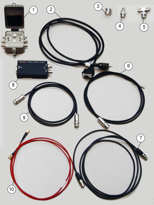
Safety precautions                                                                                 overvoltages often associated with local AC mains connections. Certain Keithley measuring
                                                                                                   instruments may be connected to mains. These instruments will be marked as category II
The following safety precautions should be observed before using this product and any              or higher.
associated instrumentation. Although some instruments and accessories would normally be            Unless explicitly allowed in the specifications, operating manual, and instrument labels, do
used with nonhazardous voltages, there are situations where hazardous conditions may be            not connect any instrument to mains.
present.
                                                                                                   Exercise extreme caution when a shock hazard is present. Lethal voltage may be present on
This product is intended for use by personnel who recognize shock hazards and are familiar         cable connector jacks or test fixtures. The American National Standards Institute (ANSI)
with the safety precautions required to avoid possible injury. Read and follow all installation,   states that a shock hazard exists when voltage levels greater than 30 V RMS, 42.4 V peak,
operation, and maintenance information carefully before using the product. Refer to the user       or 60 VDC are present. A good safety practice is to expect that hazardous voltage is present
documentation for complete product specifications.                                                  in any unknown circuit before measuring.
If the product is used in a manner not specified, the protection provided by the product            Operators of this product must be protected from electric shock at all times. The responsible
warranty may be impaired.                                                                          body must ensure that operators are prevented access and/or insulated from every
The types of product users are:                                                                    connection point. In some cases, connections must be exposed to potential human contact.
Responsible body is the individual or group responsible for the use and maintenance of             Product operators in these circumstances must be trained to protect themselves from the risk
equipment, for ensuring that the equipment is operated within its specifications and operating      of electric shock. If the circuit is capable of operating at or above 1000 V, no conductive part of
limits, and for ensuring that operators are adequately trained.                                    the circuit may be exposed.
Operators use the product for its intended function. They must be trained in electrical safety     Do not connect switching cards directly to unlimited power circuits. They are intended to be
procedures and proper use of the instrument. They must be protected from electric shock and        used with impedance-limited sources. NEVER connect switching cards directly to AC mains.
contact with hazardous live circuits.                                                              When connecting sources to switching cards, install protective devices to limit fault current and
                                                                                                   voltage to the card.
Maintenance personnel perform routine procedures on the product to keep it operating
properly, for example, setting the line voltage or replacing consumable materials. Maintenance     Before operating an instrument, ensure that the line cord is connected to a properly-grounded
procedures are described in the user documentation. The procedures explicitly state if the         power receptacle. Inspect the connecting cables, test leads, and jumpers for possible wear,
operator may perform them. Otherwise, they should be performed only by service personnel.          cracks, or breaks before each use.
Service personnel are trained to work on live circuits, perform safe installations, and            When installing equipment where access to the main power cord is restricted, such as rack
repair products. Only properly trained service personnel may perform installation and              mounting, a separate main input power disconnect device must be provided in close proximity
service procedures.                                                                                to the equipment and within easy reach of the operator.
Keithley products are designed for use with electrical signals that are measurement, control,      For maximum safety, do not touch the product, test cables, or any other instruments while
and data I/O connections, with low transient overvoltages, and must not be directly connected      power is applied to the circuit under test. ALWAYS remove power from the entire test system
to mains voltage or to voltage sources with high transient overvoltages. Measurement               and discharge any capacitors before: connecting or disconnecting cables or jumpers,
Category II (as referenced in IEC 60664) connections require protection for high transient         installing or removing switching cards, or making internal changes, such as installing or
                                                                                                   removing jumpers.
Do not touch any object that could provide a current path to the common side of the circuit under      The WARNING heading in the user documentation explains hazards that might result
test or power line (earth) ground. Always make measurements with dry hands while standing on           in personal injury or death. Always read the associated information very carefully before
a dry, insulated surface capable of withstanding the voltage being measured.                           performing the indicated procedure.
For safety, instruments and accessories must be used in accordance with the operating                  The CAUTION heading in the user documentation explains hazards that could damage the
instructions. If the instruments or accessories are used in a manner not specified in the               instrument. Such damage may invalidate the warranty.
operating instructions, the protection provided by the equipment may be impaired.                      The CAUTION heading with the             symbol in the user documentation explains hazards that
Do not exceed the maximum signal levels of the instruments and accessories. Maximum signal             could result in moderate or minor injury or damage the instrument. Always read the associated
levels are defined in the specifications and operating information and shown on the instrument           information very carefully before performing the indicated procedure. Damage to the instrument
panels, test fixture panels, and switching cards.                                                       may invalidate the warranty.
When fuses are used in a product, replace with the same type and rating for continued                  Instrumentation and accessories shall not be connected to humans.
protection against fire hazard.                                                                         Before performing any maintenance, disconnect the line cord and all test cables.
Chassis connections must only be used as shield connections for measuring circuits, NOT as             To maintain protection from electric shock and fire, replacement components in mains circuits
protective earth (safety ground) connections.                                                          — including the power transformer, test leads, and input jacks — must be purchased from
If you are using a test fixture, keep the lid closed while power is applied to the device under test.   Keithley. Standard fuses with applicable national safety approvals may be used if the rating and
Safe operation requires the use of a lid interlock.                                                    type are the same. The detachable mains power cord provided with the instrument may only be
If a screw is present, connect it to protective earth (safety ground) using the wire                   replaced with a similarly rated power cord. Other components that are not safety-related may
recommended in the user documentation.                                                                 be purchased from other suppliers as long as they are equivalent to the original component
                                                                                                       (note that selected parts should be purchased only through Keithley to maintain accuracy
The      symbol on an instrument means caution, risk of hazard. The user must refer to the             and functionality of the product). If you are unsure about the applicability of a replacement
operating instructions located in the user documentation in all cases where the symbol is              component, call a Keithley office for information.
marked on the instrument.
                                                                                                       Unless otherwise noted in product-specific literature, Keithley instruments are designed to
The      symbol on an instrument means warning, risk of electric shock. Use standard safety            operate indoors only, in the following environment: Altitude at or below 2,000 m (6,562 ft);
precautions to avoid personal contact with these voltages.                                             temperature 0 °C to 50 °C (32 °F to 122 °F); and pollution degree 1 or 2.
                                                                                                       To clean an instrument, use a cloth dampened with deionized water or mild, water-based
The      symbol on an instrument shows that the surface may be hot. Avoid personal contact to
                                                                                                       cleaner. Clean the exterior of the instrument only. Do not apply cleaner directly to the instrument
prevent burns.
                                                                                                       or allow liquids to enter or spill on the instrument. Products that consist of a circuit board with
The     symbol indicates a connection terminal to the equipment frame.                                 no case or chassis (e.g., a data acquisition board for installation into a computer) should never
                                                                                                       require cleaning if handled according to instructions. If the board becomes contaminated and
If this    symbol is on a product, it indicates that mercury is present in the display lamp. Please    operation is affected, the board should be returned to the factory for proper cleaning/servicing.
note that the lamp must be properly disposed of according to federal, state, and local laws.
                                                                                                       Safety precaution revision as of June 2017.

                                                                                                                                                                              Safety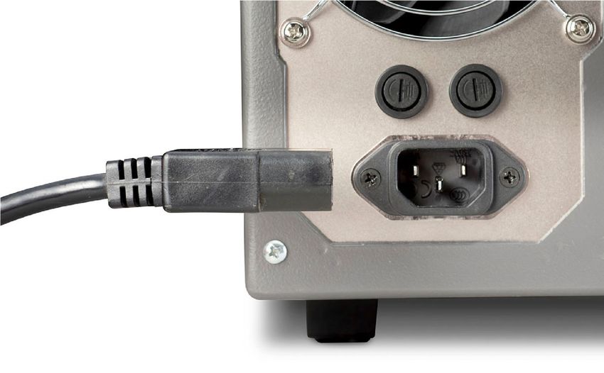
Power and environmental ratings
For indoor use only.

 Power supply          100 V ac to 240 V ac, 50 Hz to 60 Hz          CAUTION
 Maximum VA            1000 VA                                       Carefully consider and configure the appropriate
                                                                     output‑off state, source levels, and compliance levels
 Operating altitude    Maximum 2000 m (6562 ft) above sea level      before connecting the instrument to a device that can
                                                                     deliver energy. Failure to consider the output-off state,
 Operating             +10 °C to +40 °C,
 temperature           5% to 80% relative humidity, non-condensing   source levels, and compliance levels may result in
                                                                     damage to the instrument or to the device under test.
 Storage temperature   −15 °C to 60 °C,
                       5% to 90% relative humidity, non-condensing
Introduction
The 4200A-SCS and embedded Clarius software provides           •   Clarius Manual: Provides comprehensive information
clear, uncompromised measurement and analysis. The                 about projects, tests, data analyzation, data calculation,
Clarius software is furnished with embedded measurement            user libraries, and customizing Clarius.
expertise and ready-to-use applications that enable you
to perform your research with speed and confidence. The        •   Hardware manuals for setup and maintenance,
4200A-SCS-PKB High-Resolution I-V and C-V package                  source-measure units (SMUs), capacitance-voltage units
includes everything you need to perform I-V and C-V                (CVUs), pulse-measure units (PMUs) and
measurements. The Clarius user interface provides                  pulse-generator units (PGUs), and prober and external
touch-and-swipe or point-and-click control for advanced test       instrument control.
definition, parameter analysis, graphing, and automation
capabilities for modern semiconductor, materials, and          •   Programming guides for the library LPT, Keithley
process characterization.                                          User Library Tool (KULT), and Keithley External Control
                                                                   Interface (KXCI).
For additional support information, see tek.com/keithley.
The 4200A-SCS documentation includes:                          For complete documentation for the 4200A-SCS, see the
•   Quick Start Guide: This document. It provides unpacking    4200A-SCS Learning Center         . The Learning Center
                                                               contains instructional videos, PDFs, and HTML content. To
    instructions, describes basic connections, reviews
                                                               access the Learning Center, click Help in the Clarius menu,
    basic operation information, and provides a quick test     press F1 while using Clarius, or select the desktop icon.
    procedure to ensure the instrument is operational.

                                                                                          Introduction
Unpack and inspect the instrument
To unpack and inspect the instrument:
1. Inspect the box for damage.
2. Open the top of the box.
3. Remove the documentation, optional accessories and
packaging insert.
4. Carefully lift the instrument out of the box.
5. Inspect the instrument for any obvious signs of
physical damage. Report any damage to the shipping
agent immediately.
CAUTION
The 4200A-SCS weighs approximately 27 kg (60 lb) and In the 4200A-SCS-PKB bundle, you receive the 4200A-SCS
Parameter Analyzer with:
requires a two-person lift.
• Keyboard
CAUTION •
•
Mouse
Power line cord
Do not lift the 4200A-SCS using the front bezel. • Safety interlock cable
• 4201-SMU medium-power source-measure unit (two)
• 4215-CVU high-resolution capacitance-voltage unit
• 8101-PIV component test fixture
• 4200-PA remote preamplifierAlso, you should have received the following items:
1 8101-PIV component test fixture with sample devices
2 4200-RPC-2 remote preamplifier cable
3 CAP-31 protective caps with triaxial connectors (two)
4 CS-1247 SMA female-to-BNC male adapters (four)
5 CS-701 BNC tee adapters (two)
6 4200-MTRX ultra-low noise SMU triaxial cables (two)
7 Safety interlock cable
8 4200-PA remote preamplifier
9 4200-TRX ultra-low noise triaxial cables (two)
10 CA-447A SMA cables, male-to-male (four)
4200A-SCS-PKB Quick Start Guide (not shown;
this document)
Refer to the packing list for additional items that might have
shipped with your instrument.
Items shipped may vary from items pictured here.
UnpackConnect the instrument • Make sure any test fixture connected to the system
protects the operator from contact with hazardous
Important test system safety information voltages, hot surfaces, and sharp objects. Use
shields, barriers, insulation, and safety interlocks to
This system contains instruments that can produce accomplish this.
hazardous voltages. It is the responsibility of the test system
installer, maintenance personnel, and service personnel to • Double-insulate all electrical connections that an operator
make sure the system is safe during use and is operating can touch. Double insulation ensures the operator is
properly. You must also realize that in many test systems a still protected even if one insulation layer fails. Refer to
single fault, such as a software error, may output hazardous IEC 61010-1 for specific requirements.
signal levels even when the system indicates that there is no • Make sure all connections are behind a locked cabinet
hazard present. door or other barrier. This protects the system operator
It is important that you consider the following factors in your from accidentally removing a connection by hand and
system design and use: exposing hazardous voltages. Use high-reliability fail-safe
• The international safety standard IEC 61010-1 defines interlock switches to disconnect power sources when a
voltages as hazardous if they exceed 30 VRMS and test fixture cover is opened.
42.4 VPEAK or 60 V dc for equipment rated for dry • Where possible, use automatic handlers so that operators
locations. Keithley Instruments products are only rated for are not required to access the DUT or other potentially
dry locations. hazardous areas.
• Read and comply with the specifications of all instruments • Provide training to all users of the system so that they
in the system. The overall allowed signal levels may be understand all potential hazards and know how to protect
constrained by the lowest rated instrument in the system. themselves from injury.
For example, if you are using a 500 V power supply with • In many systems, during power up, the outputs may be in
a 300 V dc rated switch, the maximum allowed voltage in an unknown state until they are properly initialized. Make
the system is 300 V dc. sure the design can tolerate this situation without causing
• Cover the device under test (DUT) to protect the operator operator injury or hardware damage.
from flying debris in the event of a system or DUT failure.Wiring the interlock
NOTE If you need voltages greater than ±40 V for testing, you
To keep users safe, always read and follow all safety warnings must add an interlock switch to the fixture. This ensures
provided with each of the instruments in your system. that hazardous voltages are not present when the exterior
enclosure of the fixture is open. It also enables the
4200A-SCS to output higher voltages when the exterior
Install the instrument enclosure of the fixture is closed.
The 4200A-SCS can be used on a bench or in a rack. See
When the safety interlock signal is asserted (the switch is
the instructions that came with your rack-mount kit if you are
closed and the signal is connected to +12 V), all the voltage
installing the 4200A-SCS in a rack.
ranges of the SMUs are functional. When the safety interlock
signal is not asserted (the switch is open), the 200 V range
on the SMUs is disabled, limiting the nominal output to
±40 V.
If you need voltages greater than ±40 V, you must also
connect the exterior of the test fixture enclosure to protective
earth (safety ground). Take care to ensure that the wiring
(FORCE, GUARD, and SENSE) in the fixture does not
electrically contact the exterior of the enclosure.High-voltage test fixtures can be used with applications that
WARNING are greater than ±40 V. The test fixture has a safety interlock
switch connected to its lid. When the lid is closed, the
The 4200A-SCS is provided with an interlock circuit
interlock circuit is closed (asserted), and SMU ±200 V ranges
that must be positively activated for the high-voltage
are enabled.
output to be enabled. The interlock facilitates safe
operation of the equipment in a test system. Bypassing Conversely, the interlock circuit is open (de-asserted) when
the interlock could expose the operator to hazardous the lid is open, and the SMU ±200 V ranges are disabled.
voltage that could result in personal injury or death. High-voltage test fixtures require extra precaution to ensure
Asserting the interlock allows the SMU and preamplifier there are no shock hazards.
terminals to become hazardous, exposing the user to For correct operation with the 4200A-SCS, the test fixture
possible electrical shock that could result in personal should have a normally open switch that is used for the
injury or death. SMU and preamplifier terminals should interlock. An open interlock condition occurs when the switch
be considered hazardous even if the outputs are is open.
programmed to be low voltage. Precautions must be
taken to prevent a shock hazard by surrounding the test NOTE
device and any unprotected leads (wiring) with double
For the examples shown in this quick start guide, you do not
insulation for 250 V, Category 0. need to use an interlock. The 4200A-SCS functions on all
current ranges and up to up to ±40 V without asserting the
interlock. When the interlock is not asserted, the maximum
There are low-voltage and high-voltage test fixtures for the voltage on the SMU and preamplifier terminals is not
4200A-SCS. Low-voltage fixtures, such as the 8101-PIV hazardous.
included with this package, are intended for applications that
are less than ±40 V. For these applications, an interlock is
not needed.To connect the interlock cable: Test connections
1. Connect one end of the supplied interlock cable to If you are testing discrete devices, you need a test fixture
the rear panel of the 4200A-SCS. The location of the that is equipped with 3-lug triaxial connectors. The 8101-PIV
rear-panel interlock connector is shown in the following test fixture that is included with the 4200A-SCS-PKB allows
graphic. the 4200A-SCS to be connected to a discrete device.
For connections to a probe station for wafer testing, see the
4200A-SCS Learning Center .
NOTE
The outer shield of the triaxial cables connects the 8101-PIV
to the 4200A chassis, which connects to common.
2. Connect the other end of the connector to the test fixture.Connect a test fixture and DUT to the 4200A-SCS If you are using the supplied test fixture, connect the MOSFET and test fixture as shown in this diagram.
Item                Description                Qty                             Notes
1      4200A-SCS Parameter Analyzer            1

2      4200-TRX Ultra-Low Noise Preamplifier   2     Triaxial-to-triaxial cable that connects 4200-PA to a test
       Triaxial Cables                               fixture
3      4200-MTRX                               1     Ultra-low noise SMU triaxial cable (mini-triaxial,
                                                     connects 4201-SMU units to a test fixture)
4      TG-439 nMOSFET (DUT)                    1     Plug into the test socket that is labeled DC ONLY

5      8101-PIV Component Test Fixture         1     With sample devices

6      4200-PA Remote Preamplifier             1

7      4201-SMUs                               2
Power on the 4200A-SCS
The 4200A-SCS operates from a line voltage of 100 V to
WARNING
The power cord supplied with the Model 4200A-SCS
240 V at a frequency of 50 Hz or 60 Hz. Make sure the
operating voltage in your area is compatible. contains a separate protective earth (safety ground) wire
for use with grounded outlets. When proper connections
are made, the instrument chassis is connected to
CAUTION power-line ground through the ground wire in the
power cord. In addition, a redundant protective earth
Operating the instrument on an incorrect line voltage
connection is provided through a screw on the rear
may cause damage to the instrument, possibly voiding
the warranty. panel. This terminal should be connected to known
protective earth. In the event of a failure, not using a
properly grounded protective earth and grounded outlet
may result in personal injury or death due to electric
shock.
Do not replace detachable mains supply cords with
inadequately rated cords. Failure to use properly rated
cords may result in personal injury or death due to
electric shock.NOTE
To power on the 4200A-SCS:
1. Make sure the power is off. The power switch, on the
front panel in the lower right corner, is not lit when power When first starting a Clarius+ application, you must answer
is off.
“Yes” to an on-screen license agreement. Answering “No”
2. Plug the male end of the line cord into a properly makes your system nonfunctional until you reinstall the
grounded ac line power receptacle. software.
3. Turn on the 4200A-SCS by pushing the power switch.
The switch is lit when power is on.
The instrument starts up.Change powerline frequency To change powerline frequency:
1. Close Clarius.
NOTE 2. Run KCon.
3. From the System Configuration list, select 4200A-SCS.
The default powerline frequency is set to 60 Hz. If the setting
is wrong, the 4200A-SCS cannot properly reject powerline 4. Change the Powerline Frequency as needed.
measurement noise. 5. Select Save .Perform an I-V test on a MOSFET The first time Clarius opens, the project tree is displayed and the default project is loaded. The next graphic shows the tests in this project. To work with a test: 1. Select vds-id (located under 4terminal-n-fet).
To configure the test:
1. Select Configure to open the pane shown here. This is
    where you define the test.
2.   The vds-id settings should be:
     • SMU3: Provide a voltage step function for four
       different gate voltages (2 V, 3 V, 4 V ,and 5 V).
     • SMU2: Perform a 51-point sweep of drain voltage (0 V
       to 5 V) at each gate voltage. A current measurement
       is made at each voltage sweep point.
3.   Change the settings as needed.
4.   Select Save      .

                                                              I-V Test
Run the vds-id test Clarius can run a single test or a sequence of tests. To run a single test, check the test and select it in the project tree. The test should be highlighted. When you select , only that test will run. For example, in the following graphic, when you select , only the vds-id test will run. In the following example, one test is run. To run the vds-id test: 1. In the project tree, select vds-id to highlight it. 2. On the toolbar, select . When the test is running, Run shows two arrows circling the icon and Stop turns red: When the test is complete, Run and Stop return to normal:
To run a sequence of tests, check the tests you want to run,
then check and select the device, subsite, or project item
that contains the tests.
For example, in the following graphic, when you click   , all
the checked tests under 4terminal-n-fet run.

                                                                I-V Test
View the vds-id test results
To view vds-id test data, you can use the Analyze sheet,
which is similar to a Microsoft Excel spreadsheet, and the
graph.
To view vds-id test results:
1. Select Analyze.
2. Select an icon next to View to choose the type of
information you would like to see:
• Data and graph
• Data only
• Graph onlyExport data or graphs
Test results are automatically saved in Clarius. You can also
choose to save the data, graph, or both to an external file.
To save your test data:
1. Select Save Data.
2. On the Save Test Data As dialog box, select one of the
following buttons:
• Save Sheet: Select this to save only the sheet.
• Save Graph1: Save only Graph1.
• Save Graph2 (if available): Save only Graph2.
• Save All: Save the sheet and graphs.
I-V TestCustomize the graph
The graph shown below was customized to include the
Legend box and Title and to use different colors for the
graph series. These options are available through the Graph
Settings button.
To customize a graph:
1. Select Graph Settings.
2. To include a Legend and Title, select those options from
the Graph Settings menu.
3. To use different colors for the graph series, select
Graph Properties, then select Series. The Data Series
Properties dialog box is displayed.
4. Select the colors for each series of data.
5. Click OK. The series are displayed in the selected colors.I-V Test
Make connections for the C-V test

If you are using the supplied test fixture, connect the
nMOSFET and test fixture as shown in this diagram.
Item                    Description             Qty                    Notes
1      4200A-SCS Parameter Analyzer             1

2      CA-447A cables                           4     SMA cable, male-to-male, 100 Ω, 1.5 m

3      CS-1391 tee adapters                     2     SMA tee adapter (female-male-female)

4      8101-PIV Component Test Fixture          1

5      8101-309 (nMOSFET with S D B connected   1     Plug into PULSE IV test socket
       together (DUT))
6      4215-CVU                                 1

                                                                               C-V Test
Perform a C-V test on an nMOSFET In the Configure pane, on the next page, is where you define
the test. In the test shown, the device is connected to the
To perform a test: CVH1 and CVL1 terminals on the 4215-CVU.
1. In the project tree, select cv-nmosfet. This test is In the following graphic, note that the Gate is CVH1 and Bulk
located under the 4terminal-n-fet device. is CVL1.To define the test:
1. Select Configure. The cv-nmosfet settings should be:
• CVH1: Default setting, which is Voltage Linear Sweep,
is swept from 5 V to −5 V in −0.2 V steps with a 1 MHz
capacitance measurement made at each step.
• CVL1: Default setting, which is DC Gnd.
2. Change the settings as needed.
3. Select Save .
C-V TestRun the cv-nmosfet test In the following example, only one test is run. To run the cv-nmosfet test: 1. In the project tree, select cv-nmosfet to highlight it. 2. On the toolbar, select . When the test is running, Run shows two arrows circling the icon and Stop turns red: When the test is complete, Run and Stop return to normal:
View the cv-nmosfet test results

To view cv-nmosfet test data, you can use the Analyze
sheet, which is similar to a Microsoft Excel spreadsheet, or
the graph.
To view cv-nmosfet test results:
1.   Select Analyze.
2.   Select an icon next to View to choose the type of
     information you would like to see:

     • Data and graph

     • Data only

     • Graph only

                                                               C-V Test
Export data or graphs
Test results are automatically saved in Clarius. You can also
choose to save the data, graph, or both to an external file.
To save your test data:
1. Select Save Data.
2. If you are saving a graph, select the Graph File Format.
3. On the Save Test Data As dialog box, select one of the
following buttons:
• Save Sheet: Save only the sheet.
• Save Graph1: Save only Graph1.
• Save Graph2 (if available): Save only Graph2.
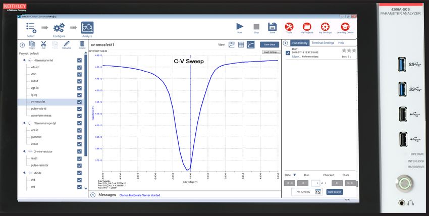
• Save All: Save the sheet and graphs.To display the graph for the cv-nmosfet test, select Graph
only.
A sample graph is shown here. In this example, the C-V curve
is measured between the gate and the source/drain/bulk.
Notice that the COX, CFB, and VFB parameters are extracted
and displayed on the screen.
You can customize graphs with options that are available
through the Graph Settings button.
C-V TestFAQs
A configuration error has been detected and I cannot
How should I clean and use the front-panel display?
launch Clarius. What should I do?
If you need to clean the front-panel LCD touchscreen display,
This occurs when the physical configuration does not
use a soft dry cloth. If necessary, use a microfiber cloth
match the configuration defined in KCon or when there are
dampened with an ammonia-free glass cleaner. Do not spray
communication problems between instruments and the
cleaning fluids onto the display. You can also use a mixture of
4200A-SCS.
70% isopropyl alcohol and 30% water.
The error can also occur if the preamplifier or RPM is
Do not use sharp objects, such as a screwdriver, pen, or
removed or reconnected. Note that preamplifiers are SMU
pencil, to touch the touchscreen. It is strongly recommended
specific. For example, a preamplifier that is configured for
to only use fingers to operate the instrument. Use of
SMU1 cannot be connected to SMU2.
clean-room gloves is supported for the touchscreen.
To verify system configuration:
My data looks odd or is wrong. What should I do?
1. Run KCon.
Verify the connections from the instrument to the test fixture.
Also, check the connections from the DUT to the test fixture 2. Select Validate.
socket.
To update the system configuration:
I cannot unplug the mini-triaxial cable (4200A-MTRX) 1. Run KCon.
from the SMU. What should I do?
2. Select Update.
The mini-triaxial connector is a locking connector. To remove
it, pull the knurled part of the connector back.Next steps
See the 4200A-SCS Learning Center , which is • Hardware manuals for setup and maintenance,
preinstalled on your system. Within the Learning Center, you source-measure units (SMUs), capacitance-voltage
will find instructional videos, PDFs, and HTML content. To units (CVUs), pulse-measure units (PMUs) and
access the Learning Center, click Help in the Clarius menu, pulse-generator units (PGUs), and prober and external
press F1 while using Clarius, or select the desktop icon.
instrument control.
The 4200A-SCS Learning Center includes the following:
• Instructional videos: Contains basic and detailed • Programming guides for the library LPT, Keithley
information about using the system that will help you User Library Tool (KULT), and Keithley External Control
with the instrument. Interface (KXCI).
• Clarius Manual: Provides comprehensive information • Application notes: Detailed applications that
about projects, tests, data analysis, data calculation, demonstrate specific applications.
user libraries, and customizing Clarius. • Datasheets: Technical data regarding the 4200A-SCS
and related accessories.
See tek.com/keithley for support and additional information
about the instrument.
FAQs and next stepsContact information: 1-800-833-9200
For additional contacts, see https://www.tek.com/contact-us Find more valuable resources at TEK.COM.
Copyright © 2021, Tektronix. All rights reserved.
Tektronix products are covered by U.S. and
foreign patents, issued and pending. Information
in this publication supersedes that in all previously
published material. Specification and price change
privileges reserved. TEKTRONIX and TEK are
registered trademarks of Tektronix, Inc. All other
trade names referenced are the service marks,
trademarks, or registered trademarks of their
respective companies.
4200A-PKB-903-01 Rev. B August 2021
*P4200A-PKB-903-01B*You can also read