PROCEEDINGS OF SPIE Efficiency of using active interference dedicated to medium range surveillance radar
←
→
Page content transcription
If your browser does not render page correctly, please read the page content below
PROCEEDINGS OF SPIE
 SPIEDigitalLibrary.org/conference-proceedings-of-spie

 Efficiency of using active interference
 dedicated to medium range
 surveillance radar

 Jędrusik, Piotr, Pietrasiński, Jerzy

 Piotr Jędrusik, Jerzy Pietrasiński, "Efficiency of using active interference
 dedicated to medium range surveillance radar," Proc. SPIE 11442,
 Radioelectronic Systems Conference 2019, 114420W (11 February 2020);
 doi: 10.1117/12.2565241

 Event: Radioelectronic Systems Conference 2019, 2019, Jachranka, Poland

Downloaded From: https://www.spiedigitallibrary.org/conference-proceedings-of-spie on 12 Dec 2020 Terms of Use: https://www.spiedigitallibrary.org/terms-of-use
EFFICIENCY OF USING ACTIVE INTERFERENCE DEDICATED
 TO MEDIUM RANGE SURVEILLANCE RADAR
 Piotr JĘDRUSIK*, Jerzy PIETRASIŃSKI*
 *
 Wojskowa Akademia Techniczna, Wydział Elektroniki, Instytut Radioelektroniki,
 [Military University of Technology, Faculty of Electronics, Institute of Radioelectronics]
 00–908 Warszawa, ul. Gen. Sylwestra Kaliskiego 2

 ABSTRACT

 This paper provides an overview of the characteristics of selected types of active interference dedicated to
 medium range surveillance radars. That is why at the very beginning examples of platforms used to interfere the
 operations of both land based surveillance radars and radars mounted on boards of combat aircraft are characterized. The
 paper focuses mostly on surveillance radars and their resistance to noise jamming. An example calculation of effective
 jamming range in relation to a medium range radar is considered in the text. Moreover a graphic representation of the
 influence of jamming on the operation of a radar with reference to the application of jamming and thereof lack are
 discussed. The basic aim of the considerations is an efficiency assessment of the jamming impact on the operation of the
 radar. Among others the effectiveness of the radar transmit pulse power changing is assessed with regard to the
 prevention of intentional jamming. The conclusions provide exemplary methods of mitigating the impact of jamming on
 the operation of the radar. Additionally the paper provides information on priorities to be taken into consideration in the
 field of contemporary radiolocation.

 Keywords: 3D radar, jamming, electronic warfare, effectiveness.

 1. INTRODUCTION
 The methods and techniques of active interference generation are rapidly developing in a frame of electronic
 warfare. Active jamming involves, among others, generation of an quasi-echo signal that adjusts to the frequency of the
 interfered radar. It is also crucial to ensure appropriate power of the jamming signal compared to the power of the real
 echo signal, . In particular, response jamming is generated with the use of a sensor (radar) probing signal. The
 jamming device analyses the probing signals of the radar in order to emulate a probing signal that is emitted – with
 appropriate delay – in the direction of the device whose operation is being distorted. As a result, several targets are
 displayed within one azimuth, thus imitating targets which are moving in the direction of the radar.
 Another example comes from noise jamming whose main purpose is to distort the operation of CFAR systems
 (CFAR – Constant False Alarm Rate). Noise jamming does not require the knowledge of the radar probing signal. Noise
 generated with appropriate power in the direction of the radar causes the CFAR level to increase, at the same time
 masking echo’s from targets with a low RCS value (RCS – Radar Crosse Section). Noise jamming “covers up” tangible
 structures whose echo disappears in the noise.
 Platforms which are used to carry the sources of jamming can be divided into ground-based and air-based ones.
 Examples of ground-based platforms used by NATO are as follows: Mini NEWVAN (Mini NATO Electronic Warfare
 Van), NEWVAN (NATO Electronic Warfare Van), Mini TRACSVAN TV (Mini Transportable Radar and
 Communications Jamming and Simulation Vans TV), TRACSVAN (Transportable Radar and Communications
 Jamming and Simulation Vans TV), MIJA (Mobile Intercept Jamming Assets), MRV (Mini Radar Van) [1]. They are
 used within NATO JEWCS (NATO Joint Electronic Warfare Core Staff). Air-based platforms are used to carry such
 pods as: AN/ALQ-167 (it comes in multiple models which differ in their operational frequencies and functions),
 AN/ALQ-99, AN/ALQ-131, AN/ALQ-184. Pods are mounted on airplanes in order to be used during air missions.
 A pod often can be reconfigured by an operator to work with a given type of radar. Jamming is the most effective if the
 distance from the radar is greater. Pods are often equipped with double transmitter systems, which allows them to
 generate jamming in both directions (front and back).

 Radioelectronic Systems Conference 2019, edited by Piotr Kaniewski, Jan Matuszewski, Proc. of SPIE
 Vol. 11442, 114420W · © 2020 SPIE · CCC code: 0277-786X/20/$21 · doi: 10.1117/12.2565241

 Proc. of SPIE Vol. 11442 114420W-1
Downloaded From: https://www.spiedigitallibrary.org/conference-proceedings-of-spie on 12 Dec 2020
Terms of Use: https://www.spiedigitallibrary.org/terms-of-use
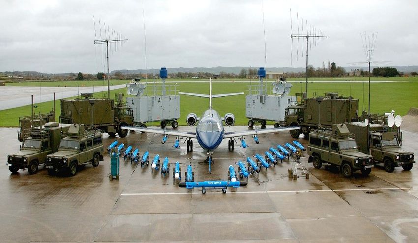
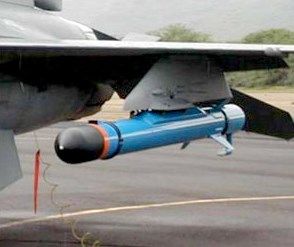
NEWVAN TRASCVAN
 DA-20 +
 Mini AN/ALQ-167 Mini
 NEWVAN TRASCVAN

 MIJA

 Figure1. Examples platforms used to generate jamming: Mini NEWVAN, NEWVAN, Mini TRACSVAN (TV),
 TRACSVAN, MIJA, AN/ALQ-167 [1]

 Several ground-based and air-based platforms is presented in Figure 1. The technological development of
 jamming pods describes trends of radiolocation development, and as a result, the need to upgrade today’s radars in order
 to counteract jamming [2].
 Pods which are equipped with signal analysis and generation systems are used to protect single aircraft or entire
 formations. The first pods were produced in 1970s, when long-range EF-111A Raven aircraft [3] and electronic warfare
 and radioelectronic combat EA-6B Prowler aircraft were first used. The latter is of such high quality that it is still used
 by the US Navy and USAF (United States Air Force) [4]. Aircraft equipped with electronic combat pods are used in
 every military operation conducted by the United States of America and NATO member states. They serve in the USAF
 as support used in COMAO (Composite Air Operations), where a total number of 60 different aircraft may be used. The
 presence of two EA-6B Prowlers allows them to neutralize the enemy’s defense systems, which in turn makes it possible
 for fighter-bombers to enter. USAF strives to replace numerous planes with a multi-task F/A-18E Super Hornet. They are
 determined to replace EA-6B Prowlers in the scope of electronic warfare. The version of Super Hornet used in electronic
 combat is marked as EA-18G Growler. These planes are equipped with ALQ-99 jamming pods [5].

 Figure 2. The structure of an ALQ-99 pod mounted under the aircraft for self-defense [6]

 Proc. of SPIE Vol. 11442 114420W-2
Downloaded From: https://www.spiedigitallibrary.org/conference-proceedings-of-spie on 12 Dec 2020
Terms of Use: https://www.spiedigitallibrary.org/terms-of-use
An ALQ-99 pod carried by the EA-18G Growler is shown in Figure 2. In the front part of the pod there is a
 turbine which generates independent power supply for the pod. This system is not a burden to the aircraft during an
 operation (there is no need for a power generator for the pod). The pod is covered by a Radome which protects the
 antennae and the whole equipment against weather conditions such as rain or wind. EW elements used in the EA-18G
 Growler make it the most expensive aircraft manufactured in the USA. The plane is able to defend itself against other
 objects which operate in air. Such a highly advanced self-defense technology allows it to disarm other airplanes and
 ground-based exploratory devices and the pods allow to jam the enemy’s communication or other defense systems, as a
 result protecting the aircraft or the entire COMAO formation. Pods are formed in various combinations and frequency
 ranges. Several selected pods are described below.
 AN/ALQ-211 pod (SIRFC- Suite of Integrated RF Countermeasures) [7] is a part of the AN/ALQ family, a radio
 frequency countermeasure set. An integrated combat system provides protection against aircraft radio hazards. The pod
 is also equipped with a system which notifies the pilot of radiation. Such a system is utilised in F-16 aircraft which form
 a part of the Polish Air Force.
 .

 Figure 3. An AN/ALQ-231 pod [8]

 The ALQ-231 pod utilised by the US Marine Corps is a system which covers the network technology
 (architecture) and combines all defense systems in an aircraft (EWASA- Electronic Warfare Service Architecture) [8].
 The system allows for pod control from the plane, but also by means of a safe tactile radio network, which is why it may
 also be used in unmanned aircraft. The visual side of the ALQ-231 pod is shown in Figure 3. The lack of a turbine
 requires external power supplied by the plane.

 2. RADIOLOCATION JAMMING
 2.1. Types of jamming used in radiolocation
 Radiolocation jamming may be categorised under various criteria. They are mainly divided into active and
 passive. The following list presents the categorisation of active radioelectronic jamming [9]:
 − with regard to the jamming bandwidth: selective, barrage, multipoint, jitter;
 − with regard to the structure of the jamming signal: modulated, manipulated, impulse, combined
 interference;
 − with regard to the impact range: close-range, long-range;
 − with regard to the duration of jamming: short-term, long-term;
 − with regard to the radiation of the jamming signal: directional, omnidirectional;
 − with regard to the type of radiation: weak, strong, very strong.

 Proc. of SPIE Vol. 11442 114420W-3
Downloaded From: https://www.spiedigitallibrary.org/conference-proceedings-of-spie on 12 Dec 2020
Terms of Use: https://www.spiedigitallibrary.org/terms-of-use
The above taxonomy is one of several categorisations used in Polish and foreign nomenclature and it was taken
 from The Air Force Electronic Warfare Manual[10]. The direction of development in NATO in the scope of EW is
 regulated by the document MC 0064 – NATO Electronic Warfare Policy[11]. It is developed and regularly updated by
 NEWAC (NATO Electronic Warfare Advisory Committee) and approved by NATO MC (NATO Military Committee).
 The directions of development in the scope of EW are formulated on the basis of these documents in the member
 states of NATO, including the Polish Armed Forces.
 Noise jamming is categorised with regard to the structure of the signal (broadband and narrowband), amplitude
 modulation and repeat time (pulse repetition interval). In this paper prohibitive noise jamming with 20MHz broadband is
 subject to an analysis. While the operating band of the jamming signal increasing, the loss of power must be taken into
 account [12]. Designing a broadband jamming device requires a very high level of device power supply. It is not an issue
 in ground-based devices, however, it becomes a huge drawback in aircraft-mounted devices [2].

 2.2. Effectiveness of the use of jamming
 There are numerous ways of assessment of the effectiveness of radiolocation jamming cited in reference
 publications. The type of jamming signal and the characteristics of the interfered device are of significance here. The
 effectiveness is represented as the ratio of the interference power to the power of the useful signal of the interfered
 device [13].

 =( ) ≥ (1)

 where: − input interference power of the radiolocation receiver, − input useful signal power of the receiver,
 − degradation index of the radiolocation device [13,14,15]. The application of the above index allows to determine
 the power of the jamming signal at a given distance, , required to ensure appropriate loss of radiolocation data with
 a set value of the probability of aircraft echo detection.
 According to EW specialists the degradation index of a given radar ranges from 3 to 8. For impulse radars the
 value is closer to 8. The value of the factor depends on the parametres of the interfering device, the interfered radar and
 their respective dislocation. The following considerations present the correlations for an interfering device mounted on
 an interfering aircraft in order to cover another plane flying in the direction of the enemy’s radar.
 The input power of the jamming radar signal can be determined in the following way [14]:
 = 2 ( , ) + (2)
 where:

 −interfering signal power density measured at the antenna input of the interfered radar [ 2];
 − effective surface of the antenna aperture of the interfered radar [ 2 ];
 2 ( , ) − function which describes normalised directional characteristics of the interfered radar;
 − an index which determines the difference between the radar antenna polarisation and the interfering device

 The power of self-noise created in the receiver of the interfered radar, , is calculated with the use of the
 following correlation [16]:
 = ∆ (3)
 where:
 − Boltzmann constant;
 − absolute temperature;
 − receiver noise index;
 ∆ − the width of the operating band of a receiver part in the interfered radar

 Proc. of SPIE Vol. 11442 114420W-4
Downloaded From: https://www.spiedigitallibrary.org/conference-proceedings-of-spie on 12 Dec 2020
Terms of Use: https://www.spiedigitallibrary.org/terms-of-use
The power of the jamming signal which reaches the radar is usually much higher than the power of the receiver
 noise, , which is why it is omitted in the calculation in the majority of studies.

 The power of the input useful signal of the radar receiver is described as follows [16]:

 −0,2
 = 4 2 4 2 10 (4)

 By using the above correlations in the equation (1), the quotation for radiolocation prevention looks as follows
 [14,15]:
 4 ∆ 4
 =( ) = 2( , )100,1 (2 − ) (5)
 o∆ 2

 where:
 −the power of the interfering transmitter, taking into account the losses in the transmission line [ ];;
 − the power of the interfered transmitter, taking into account the losses in the transmission line [ ];
 − directivity of the antenna of the interfering transmitter;
 − directivity of the antenna of the interfered device;
 ∆ −spectrum width of the jamming signal [ ];
 ∆ − spectrum width of the signal received by the interfering device receiver [ ];
 − an index which takes into account the difference between the polarization values of the antennae of the
 jamming transmitter and the interfered device;
 − an index which takes into account the reduction of the signal in the atmosphere;
 − the distance between the aircraft (interfering transmitter) and the interfered device [ ];
 − the distance between the covered aircraft and the interfered device [ ];
 0 − radar cross section [ 2] ;

 By using the equation (5) it is possible to determine the characteristics of electronic warfare pods and to calculate
 the jamming influence on a chosen type of radar. By knowing the parameters of the radar and the pod, the value of the
 distance is established – within a given distance jamming applied with a specified power is ineffective, which
 makes it possible to detect the aircraft which carries the pod and the assisting aircraft which was masked.
 ∆
 = √4 (6)
 ∆

 The equation (6) [17] is correct if the value ≈ 0 of the electromagnetic wave suppression in the atmosphere is
 omitted and if = . This correlation determines the minimum distance which proves that the radar jamming is
 ineffective.

 3. TEST RESULTS
 3.1. Examples of calculations of the impact of the change of interference power on effective radar range
 The calculations were made with reference to medium range radars for the L band and S band and for example
 parameters of an jamming transmitter mounted on an aircraft with average radar cross section = 2 2 [13, 14, 15].

 Proc. of SPIE Vol. 11442 114420W-5
Downloaded From: https://www.spiedigitallibrary.org/conference-proceedings-of-spie on 12 Dec 2020
Terms of Use: https://www.spiedigitallibrary.org/terms-of-use
Moreover, an assumption was made that the pod is mounted on the aircraft for self-defense purposes and the interfered
 radar is located on the ground. The atmosphere suppression value was disregarded. The following assumptions were
 made:
 = , = = 0, 2 ( , ) = 1, = 0.

 The following parameters values of the jamming transmitter were used:
 = 150 ÷ 1500 ;
 = 21 ;
 ∆ = 5 ;
 = 0,7

 Radar 1 parameters (examples): Radar 2 parameters (examples):
 = 0,3 ; = 1,4 ;
 = 30 ; = 30 ;
 ∆ = 4 ∆ = 4
 = 6,0 = 6,0

 Table 1 The influence of the change in the power of the jamming device on effective jamming range

 P [W] 150 300 450 600 750 900 1050 1200 1350 1500

 Radar 1 [km] 70 49 40 35 31 29 26 25 23 22

 Radar 2 [km] 151 107 87 75 67 62 57 53 50 48

 The calculations results concerning a minimum distance listed in [km] necessary to detect a jamming aircraft
 flying towards the radar are presented in the Table 1. Radar 2 has a considerably higher power than the first one, which
 allows for the possibility of an earlier detection of a jamming device in the radar space. The examples of calculations
 presented above highlight the importance of the power of emitted signal. A much larger range of the second radar allows
 the operator more time to react.
 Additionally, the above considerations did not involve the atmosphere suppression value, which would only
 slightly influence the results. The change of the transmitter power which is visible here shows how the effective jamming
 range undergoes changes. A radar which emits a stronger impulse is able to detect a jamming transmitter almost twice as
 fast, which is confirmed by the results of calculations presented in the table.

 3.2. Checking the impact of jamming on a medium range radar
 Numerous scenarios of electronic warfare are performed during different tests. The examples of scenarios
 performed while using active prohibitive noise jamming are shown in Figure 5 and Figure 7.

 Proc. of SPIE Vol. 11442 114420W-6
Downloaded From: https://www.spiedigitallibrary.org/conference-proceedings-of-spie on 12 Dec 2020
Terms of Use: https://www.spiedigitallibrary.org/terms-of-use
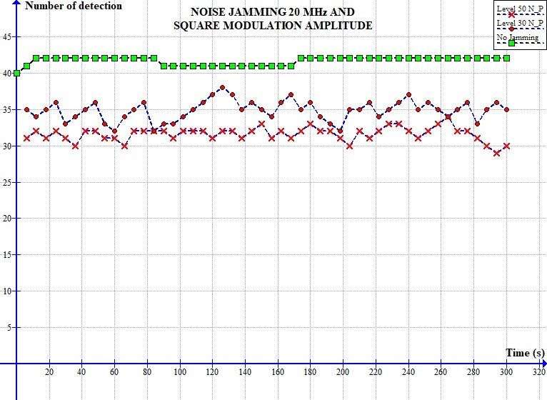
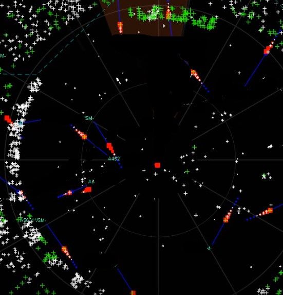
Figure 4.The graph shows the correlation between the number of plots in the transmitter and the time of jamming
 activities for uninterrupted work and a correction of the Neyman-Pearson detection threshold with the application of
 20 MHz noise jamming with square modulation amplitude (prepared by the authors)

 The first stage of the test focused on prohibitive noise jamming with square modulation amplitude. The number of
 received plots are shown in Figure 4. Three types of operation were analysed: normal operation, work with jamming
 elements and an attempt to mitigate the results of jamming. A 20MHz band jamming is powerful, which results in a
 strong impact on the radar. The green colour indicates results of the radar operation without any impact of the jamming
 activities. A constant number of plots (detections) is visible in the receiver block. Red crosses and points indicate the
 number of plots during the period of jamming impact. A loss of detections is visible, which proves the fact that the
 CFAR threshold has increased significantly. Objects with a low RCS value are covered with noise in the receiver. Seeing
 a loss of plots on the display for aircraft flying on specific routes, the operator adjusts the value of the Neyman-Pearson
 detection threshold. Lowering the threshold results in the increase of detections, which has been indicated with red points
 (Figure 4). Lowering the detection threshold too much leads to detection of noise, which in turn results in a very high
 number of false detections.
 If the Neyman-Pearson detection threshold is set in a correct way, the difference in echo detection is noticeable.
 Too low threshold value results in detection of lost plots and, additionally, in detection of a high number of random plots
 which are not real objects.

 Figure 5. Depiction of the radiolocation situation in normal operation without jamming and with the application of
 noise jamming (prepared by the authors).

 Proc. of SPIE Vol. 11442 114420W-7
Downloaded From: https://www.spiedigitallibrary.org/conference-proceedings-of-spie on 12 Dec 2020
Terms of Use: https://www.spiedigitallibrary.org/terms-of-use
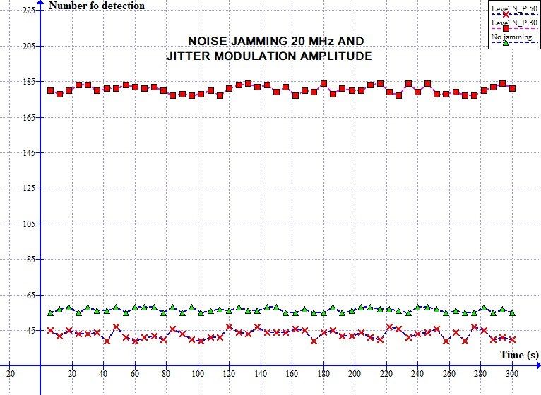
The display of a medium range radar is presented in Figure 5. The green colour shows current detections, while
 the colour white indicates pulses (histories) from the previous rotation of the antenna. The blue colour shows a tracked
 route. The right side of Figure no. 3 shows the result of the active jamming on the radar. Yellow arrows indicate losses of
 plots of schedule objects (with a high ERS value). Also visible is the loss of other plots generated around the radar. The
 red colour indicates repeated information from objects, collected with the help of the IFF system (Identification Friend or
 Foe). If the IFF system fails to identify an element, the operator loses their ability to track the objects.

 Figure 6. The graph shows the correlation between the number of plots in the transmitter and the time of jamming
 activities for a change in the detection threshold with the application of 20 MHz prohibitive jamming with jitter
 modulation amplitude (prepared by the authors)

 Lowering the value of the threshold to 30 (while the value for normal operation conditions is 100) results in a
 fourfold increase of the number of detected plots, which is shown in Figure 6. The majority of detections are false plots,
 not connected to real objects. Detections can be randomly observed in various azimuths around the radar as they are
 generated in all directions in large groups of plots and mask real objects.

 Figure 7. Depiction on the radar display with an incorrectly selected Neyman-Pearson detection threshold (prepared
 by the authors).

 Proc. of SPIE Vol. 11442 114420W-8
Downloaded From: https://www.spiedigitallibrary.org/conference-proceedings-of-spie on 12 Dec 2020
Terms of Use: https://www.spiedigitallibrary.org/terms-of-use
Correctly selected detection threshold depends on numerous factors in the radar operation. Weather conditions
 and the type of jamming applied disruption all influence the correct setting of the threshold. Operation in normal
 conditions requires the range of the threshold of 100-150 range. Lowering the threshold results in an increased sensitivity
 of the receiver. The appropriate selection of the detection threshold is crucial in jamming combat. Additionally, the
 operator is able to control the range threshold (RTC – Range Threshold Control). In the cases presented in the paper the
 value of RTC has not been adjusted in order to show the impact of the change in the value of the Neyman-Pearson
 detection threshold. The characteristics of RTC are strictly determined by the manufacturer of a given device, which
 allows for its adjustment through changing the index of a characteristic feature corresponding to its shape. Adjustment of
 the value of the index removes the excessive number of plots generated in close proximity of the device, usually within a
 70 km radius from the site of the radar.
 Appropriate selection of the index is crucial in combat operation of the device, as it allows to avoid sending false
 plots to superior officers working on the basis of radiolocation information.

 Figure 8. Depiction of a case of failed detection of a plane which uses a pod for self-defense purposes.

 The self-disguise effect of an aircraft which uses a pod mounted on the board is shown in Figure 8. Purple shading
 informs us on the direction of the emitted jamming. Identification is possible only with the application of the IFF system
 (Identification Friend or Foe). The object was marked with a yellow arrow. Only detection in the secondary system (red
 squares) is possible. If the radar is not equipped with the IFF system, an aircraft remains invisible until it crosses the
 distance, where jamming is ineffective. An experienced operator with the knowledge about a jamming emitter
 within a given azimuth can undertake actions in order to ensure that the jamming is deliberate. The easiest way of
 establishing deliberate jamming is to observe neighbouring aircraft in order to determine the loss of plots in a given
 azimuth. The loss of real objects occurs in the scope of activity of a jamming emitter.

 3.3. Analysis of the results
 If a jamming device generates a noise signal, the average level of noises increases in the radar receiver. Therefore,
 in order to “produce” a relatively constant number of false plots (do not overload the receiver with a very high number of
 false detections), the CFAR system must increase the decision threshold [14]. At this time lower echoes, which in normal
 conditions would pass the CFAR threshold, will be filtered out and not admitted for further signal processing (they will
 be masked). Echoes with a high RCS value which pass the threshold will be processed further [18, 19, 20].
 The effectiveness of changes in the frequency of the device operation was also verified during the tests. Changes
 in the frequency caused an escape from the interfered frequency, which resulted in operation similar to normal
 conditions. The effect of jamming performed with the use of a device located approx. 1 km from the interfered radar is
 presented in Figure 5. If a device (POD’s) is located within a short distance, it is possible to determine the direction of
 the emitted jamming signal. It is a very significant piece of information needed in order to locate the jamming emitter
 and to remove it accordingly.

 Proc. of SPIE Vol. 11442 114420W-9
Downloaded From: https://www.spiedigitallibrary.org/conference-proceedings-of-spie on 12 Dec 2020
Terms of Use: https://www.spiedigitallibrary.org/terms-of-use
4. CONCLUSIONS
 An important aspect of contemporary radiolocation is the development of defense techniques against
 radioelectronic jamming. The use of ever newer methods of disrupting surveillance radars causes difficulties in fighting
 them. Although the new radars have many possibilities of interference in the transmitter parameters such as: Neyman-
 Pearson detection threshold, RTC, transmitter power control, change of duration of the probing impulse, change of
 refresh time of the radiolocation information etc. are considered in the paper. Appropriate application of the radar’s
 capabilities offers a high chance of success in the process of jamming defense. An important element in EW is the level
 of training received by the appropriately trained staff. A well-trained operator is able to reconfigure the radar in an
 appropriate way to counteract intentional jamming. The training should focus on practical usage of a radar in the
 presence of intentional jamming. The knowledge of methods and techniques of counteracting intentional jamming
 guarantees approximately a 70% success rate of defense. The characteristics of interference and their influence on the
 operation of the radar should be sent to the remaining users of the air defense SYSTEM, as the forwarded information
 ensures that the jamming emitter is detected much quicker. If the direction of interference changes the remaining devices
 which operate in the air defense SYSTEM can easily hold off the attack. That is why the main priority in the
 contemporary radiolocation is practical training of staff members during allied forces training sessions. The number of
 practical trainings results in the increase of staff experience and further success in dealing with intentional jamming.

 Publication financed by the Military University of Technology in 2019 under the PBS 659
 project.

 REFERENCES

 [1] NATO JEW CORE “A History of Transformation” (10 September 2019);
 [2] Jędrusik P., Pietrasiński J., „Properties of aircraft pods in the aspect of the electronic warfare”, Electronic nr 6,
 SIGMA-NOT, 2019;
 [3] F-111 Aardvark - USAF's Ultimate Strike Aircraft, Tony Thornborough, Osprey Aerospace, 1993;
 [4] United States Military Aircraft Since 1909, Gordon Swanborough and Peter M. Bowers, Smithsonian, 1989;
 [5] Electronic Warfare and Radar System Engineering Handbook, Point Mugu, CA 93042, NAWCWD TP 8347 Fourth
 Edition, 2013;
 [6] (10 September 2019);
 [7] (10 September 2019);
 [8] 10 September 2019;
 [9] EW in Polish Air Force. Manual Edition Air Force Command , Recognition and EW Management, Warsaw, 2010;
 [10] (10 September 2019);
 [11] (10 September 2019);
 [12] David L. Adamy „EW 101 A First Course in Electronic Warfare”, Artech house, Boston London, 2000, ISBN: 1-
 58053-169-5;
 [13] Leroy B., Applied ECM. Vol. I, II, III. EW Engineering, Inc P.O. Box 28, Duun Lorgin, VA22027, USA, 1991;
 [14] Matuszewski J., “Evaluation of jamming efficiency for the protection of a single ground object”, 2017
 Radioelectronic Systems Conference, Jachranka, Poland, Nov 14-16, 2017, Proc. of SPIE 10715, 107150B (19
 April 2018); DOI: 10.1117/12.2316629 (2018);

 Proc. of SPIE Vol. 11442 114420W-10
Downloaded From: https://www.spiedigitallibrary.org/conference-proceedings-of-spie on 12 Dec 2020
Terms of Use: https://www.spiedigitallibrary.org/terms-of-use
[15] Matuszewski J., “Jamming Efficiency of Land-Based Radars by the Airborne Jammers”, MIKON 2018 - 22nd
 International Microwave and Radar Conference, Poznań 2018, pp. 324-327. DOI: 10.23919/MIKON.2018.8405214
 (2018);
 [16] Merrill Skolnik, „Radar Handbook” Third edition, McGraw-Hill, 2008, ISBN: 978-0-07-148547-0;
 [17] David L. Adamy „EW 102 A Second Course in Electronic Warfare”, Artech house, Boston London, 2004;
 [18] U.S. Department of Defense: „Electronic Warfare Fundamentals”, 2014;
 [19] Naval Air Warfare Center Weapons Division : „Electronic Warfare and Radar Systems Engineering Handbook”
 Fourth Edition, Point Mugu, California, 2013;
 [20] Welch M., Pywell M., „Electronic Warfare Test and Evaluation”, RTO AGARograph 300 Flight Test Technique
 Series – Volume 28, 2012.

 Proc. of SPIE Vol. 11442 114420W-11
Downloaded From: https://www.spiedigitallibrary.org/conference-proceedings-of-spie on 12 Dec 2020
Terms of Use: https://www.spiedigitallibrary.org/terms-of-use
You can also read