SPECTRACOOL Remote Access contRol
←
→
Page content transcription
If your browser does not render page correctly, please read the page content below
SPECTRACOOL
Remote Access Control


INSTRUCTION MANUAL
Rev. O   © 2021 nVent   P/N 89091002   89091001
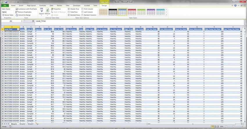
TABLE OF CONTENTS
  Warranty and Return Policy.............................................................................................................................................................. 2
        INTRODUCTION............................................................................................................................................................................................... 3
        ENERGIZING THE CONTROLLER................................................................................................................................................................... 3
        CONTROL STATUS INDICATION.................................................................................................................................................................... 3
        DISPLAYING AND CHANGING PROGRAM VARIABLES............................................................................................................................... 4
        OPERATING PARAMETERS............................................................................................................................................................................ 4
        ALARM PARAMETERS.................................................................................................................................................................................... 4
        OPERATING PARAMETERS............................................................................................................................................................................ 5
        ALARM PARAMETERS.................................................................................................................................................................................... 5
        OPERATING REAL-TIME CLOCK (RTC) PARAMETERS................................................................................................................................. 5
        DISPLAYING TEMPERATURE SENSOR #2.................................................................................................................................................... 5
        COMPRESSOR RESTART TIME DELAY.......................................................................................................................................................... 5
        ALARM OUTPUT CONTACT............................................................................................................................................................................ 5
        ALARM INPUT CONNECTION......................................................................................................................................................................... 5
        ALARM CONDITION DISPLAY........................................................................................................................................................................ 5
  Primary-Secondary CAPABILTY (OPTIONAL)................................................................................................................................. 6
        Primary-Secondary ALARM INPUT CONNECTION....................................................................................................................................... 8
  REMOTE ACCESS CONTROL........................................................................................................................................................... 8
        AIR CONDITIONER UNIT COMMUNICATION FEATURES............................................................................................................................. 8
             USB COMMUNICATION........................................................................................................................................................................... 8
             ETHERNET COMMUNICATION............................................................................................................................................................... 8
             Primary-Secondary CAPABILITY (OPTIONAL)...................................................................................................................................... 8
        USING THE PC INTERFACE TOOL.................................................................................................................................................................. 9
             USB COMMUNICATION MODE............................................................................................................................................................... 9
             ETHERNET COMMUNICATION MODE................................................................................................................................................... 9
        Instructions for configuring Email or SMS when there is an ACU fault.................................................................................................... 34
        Basic Air Conditioning Trouble Shooting Check List - Remote Access Control Version	������������������������������������������������������������������������ 40
        Symptoms and Possible Causes - Remote Access Control Version........................................................................................................ 41

           NOTE: Some of the information in this manual may not apply if a special unit was ordered. If
           additional drawings for a special unit are necessary, they have been inserted. Contact nVent
           Electrical if further information is required.

WARRANTY AND RETURN POLICY
https://hoffman.nvent.com/en-us/cooling-warranty-registration

-2-                                                                            © 2021 nVent                                                                                                               89091001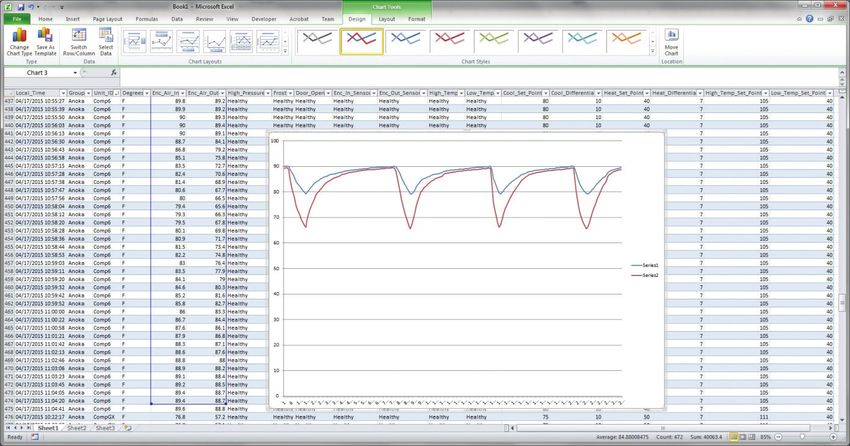
INTRODUCTION
The Remote Access Control is a parametric controller for the complete management of air conditioners. All
settings are pre-programmed at the factory. Cooling/heating set-points, cooling/heating differential and high /low
temperature alarm set-points can be adjusted by the user. Alarms are outputted through a relay contact and also
can be accessed through an Ethernet connection utilizing SNMP, EtherNet/IP, Modbus TCP, and PROFINET. A USB
connection is also provided and can be used to interface with the controller utilizing Modbus RTU.
MOUNTING THE CONTROLLER
The Remote Access Control must be mounted and enclosed inside a tool access enclosure. This Remote Access
Control comes with a DIN rail and a DIN rail mounting bracket; see below for DIN rail mounting dimensions. The
communication ports and alarm input/output terminals are located underneath the Remote Access Control.
When installing, allow sufficient space under the Remote Access Control for access to communication ports and
alarm input/output terminals.


                                                                 5 ;


                                                                                              ;
                                     ;
                                            89062967

                                                                         ;


ENERGIZING THE CONTROLLER
The controller is wired and programmed at the factory to be energized when power is supplied to the air
conditioner. The controller will default to the standalone operating mode when powered the first time. Primary-
Secondary operating mode is optional and will require additional setup.

CONTROL STATUS INDICATION
The display has numerous symbols that indicate if the controller is heating, cooling, alarming, if the compressor
is enabled, and if the ambient fan is enabled. The 3 alpha-numeric characters further describe alarms and show
the cabinet temperature by default.
           NOTE: The Slim Fit air conditioners DO NOT come standard with a heating option.

89091001                                       © 2021 nVent                                                       -3-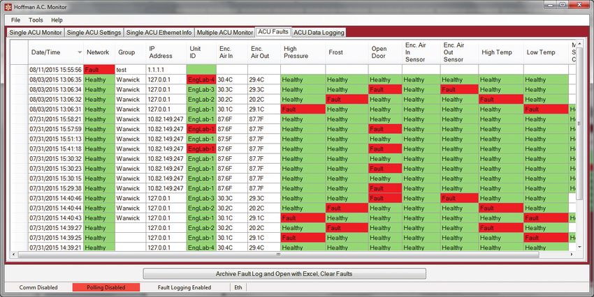
SYMBOL          COLOR                 ICON ON                                             ICON FLASHING
                                                               3. Flashing at start up request is standalone mode
                             1. Compressor On                  4. Primary-Secondary Mode:
      1,2,3,4    AMBER       2. TLAN Device ID                      1: TLAN Primary.
                                                                    2,3,4: TLAN Secondary. Device ID 2,3,4 are not active in standalone
                                                                    mode
        A        AMBER              Compressor On                                  Active when compressor is ON
        B        AMBER            Evaporator Fan On                                        Start-up Request
        C        AMBER                 Not Used                                                Not Used
        D        AMBER               Primary Unit                              Active when this is the TLAN Primary
        E        AMBER               Heater Active                                     Not Used (always OFF)
        F         RED                Alarm Active                               Active if there is an alarm condition
                                                                   ON indicates power and activates all functions. OFF indicates
        G        AMBER             Controller Active                 controller is in standby mode and all functions are OFF
        H        AMBER                 Not Used                                        Not Used (always OFF)

            NOTE: On the smart controller, the display symbols for “H” and “E” are always OFF. If they
            turn ON, simply hold the       “sun” button for greater than 5 sec to turn OFF. The electric
            heater “E” symbol is required to minimize the heating setpoint (parameter A04) and/or defrost
            setpoint (parameter A01). Then, hold the     “Cooling” button for great than
            5 sec to turn ON the snowflake symbol (“G”).

DISPLAYING AND CHANGING PROGRAM VARIABLES
Access: To view and/or change parameters, press and hold the Prg and Sel buttons for greater than 5 seconds.
Press the up or down arrow buttons until “22” is displayed, then press Sel button. When “S-P” is displayed, press
Sel.
Navigation: Press up or down arrows to display sub-menus then press Sel to select the desired sub-menu. In the
sub-menu, use up or down arrows to display parameters for viewing or changing and press Sel. Use Prg button to
back out of menu levels as desired.
Adjust: Use the up or down arrows to change the parameter value then push Sel to save that setting. If Sel is not
pressed, the change to the value will not be saved. Navigate to and change other parameters as desired. When
finished, push Prg to back out of the sub-menus to the main menu.
            NOTE: The display will revert to normal temperature display mode if no buttons are pressed
            for 60 seconds.

       MODELS WITH °C CONTROLLER
       Cooling turns ON at r01 (setpoint) and OFF at r01 (setpoint) – r02 (differential).
       For example, using default values form the table below, cooling will turn ON at 35°C (setpoint) and turn
       OFF at 30°C (setpoint – differential).
                                                    OPERATING PARAMETERS
                 Parameter                          Description                         Default Value                 Range
                    r01                           Cooling set-point                           35 C                 20 C to 55 C
                    r02                          Cooling differential                         5C                           -
                   P08                Door Open and/or smoke detected                         28                      4 or 28

                                                       ALARM PARAMETERS
                Parameter                    Description                          Default Value                    Range
                  P16                  High Temperature Alarm                          55 C                            -
                  P19                  Low Temperature Alarm                           14 C                            -

-4-                                                 © 2021 nVent                                                                  89091001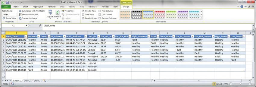
MODELS WITH °F CONTROLLER
    Cooling turns ON at r01 (setpoint) + r02 (differential), and OFF at r01 (setpoint).
    For example, using default values form the table below, cooling will turn ON at 87°F (setpoint +
    differential), and turn OFF at 80°C (setpoint).
                                            OPERATING PARAMETERS
             Parameter                       Description                    Default Value             Range
                 r01                      Cooling set-point                        80 F            72 F to 120 F
                 r02                     Cooling differential                      7F                      -
                P08              Door Open and/or smoke detected                   28                 4 or 28

                                                ALARM PARAMETERS
            Parameter                   Description                    Default Value                Range
               P16                High Temperature Alarm                   125 F                      -
               P19                Low Temperature Alarm                    40 F                       -

                             OPERATING REAL-TIME CLOCK (RTC) PARAMETERS
              Parameter               Description               Default Value                    Range
                  t01                    Hour                         0                          0 to 23
                  t02                   Minute                        0                          0 to 59
                  t03                    Day                          1                          1 to 31
                  t04                   Month                         1                          1 to 12
                  t05                    Year                         3                          3 to 99

DISPLAYING TEMPERATURE SENSOR #2
Both the air inlet sensor (b01) and outlet or evaporator coil sensor (b02) can be reviewed at any time by
pressing the up and down arrow button on the front panel of the controller display. The display will revert to the
temperature sensor number b01 (air inlet temperature) or b02 (air outlet temperature) after 60 seconds. Both
sensors can also be read through the Ethernet and USB connections with optional remote access communication
board.
COMPRESSOR RESTART TIME DELAY
A factory set 5 minute (360 second) restart delay exists to reduce residual back pressure before allowing the
compressor to restart. The compressor will stay off for the entire restart duration after the compressor is
disabled. A flashing “1” on the controller display will indicate the unit is in a compressor restart delay while calling
for cooling. If the delay time is reduced to less than 5 minutes, this may cause reduced compressor life.

ALARM OUTPUT CONTACT
The smart controller has a normally open dry contact alarm output with a resistive load rating of 250 VAC to
3 Amp. The 6-POS connector terminals 3 and 4 (marked YEL/ALARM) located on the enclosure side of the
unit provides a connection to this output. The optional Remote Access Communication board can accept this
normally open dry contact alarm from the smart controller..

ALARM INPUT CONNECTION
The smart controller can accept a dry contact/switch input via the 6-POS connector terminals 1 and 2 (marked
WHT/DS1 and WHT/DS2), located on the enclosure side of the unit. This input is associated with the controller
display alarm mnemonic “tP” (door open and/or smoke detected). Note that the door open and/or smoke
detected is pre-programmed at the factory as “Normally Open”. The optional Remote Access Communication
board can accept this door open and/or smoke detected alarm from the smart controller. To use this feature,
simply connect the customer supplied wires from the cabinet door switch to DS1 and DS2 terminals.

ALARM CONDITION DISPLAY
There are eleven possible non-latching alarm conditions detectable by the controller and are indicated on the
controller display. All alarms can also be accessed through the Ethernet and USB connections with the optional
remote access communication board.
89091001                                       © 2021 nVent                                                          -5-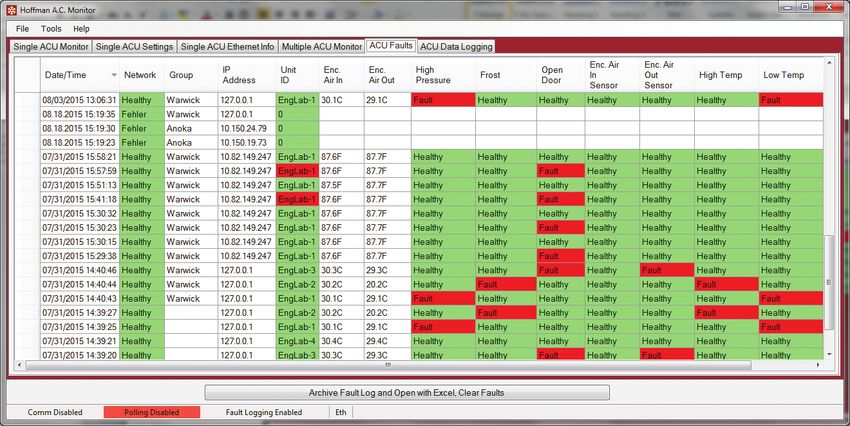
Alarm
                            Description                          Cause                               Result                   Alarm Relay
      Mnemonic
                                                                                           Unit turns OFF for duration
          tP              General Alarm            Door open and/or smoke detected                                        Relay Contact closed
                                                                                                    of alarm
                                                    MALF high pressure switch opens
          LA          High Pressure Warning                                                  No effect on function                N/A
                                                          (see note 3 below)
                                                   Low pressure switch open (see note
          LP            Low Pressure Alarm                                                   No effect on function        Relay Contact closed
                                                               4 below)
                    Air Inlet Temperature Sensor
          E1                                                 Sensor failure                    See note 1 below           Relay Contact closed
                                Alarm
                      Air Outlet Temperature
          E2                                                 Sensor failure                    See note 2 below           Relay Contact closed
                           Sensor Alarm
                     High Temperature Alarm,        Air inlet temperature greater than
          Ht                                                                                 No effect on function        Relay Contact closed
                          default = 55°C                           55°C
                     Low Temperature Alarm,
          Lt                                       Air inlet temperature less than 14°C      No effect on function                N/A
                         default = 14°C
                                                   Air outlet temperature less than or     Compressor and Condenser
          A1                Frost Alarm                                                                                   Relay Contact closed
                                                              equal to -1.0°C             fan OFF for duration of alarm
                                                     High pressure switch open (see        Unit turns OFF for duration
      HP/HP1       High Pressure Serious Alarm                                                                            Relay Contact closed
                                                             note 5 below)                          of alarm
                                                   The Primary cannot communicate
                                                       with any Secondary, or the         No effect on function. Unit
          LC        Lost Communication Alarm                                                                                      N/A
                                                    Secondary cannot communicate          will enter standalone mode
                                                            with the Primary
                                                   The Primary cannot communicate         No effect on function. Unit
          LC1       Lost Communication Alarm                                                                                      N/A
                                                      with one of the Secondarys          will enter standalone mode

            NOTE 1: Air inlet temperature sensor will default to air outlet temperature sensor. Cooling setpoint
            default to 10°C.
            NOTE 2: Unit continues to operate without evaporator freeze protection.
            NOTE 3: The MALF high pressure switch is optional.
            NOTE 4: The Low Pressure switch is optional.
            NOTE 5: The High Pressure (HP) or High Pressure Serious (HP1) switch is optional.

PRIMARY-SECONDARY CAPABILTY (OPTIONAL)
The Primary-Secondary capability is included as standard and can accommodate up to four (4) air conditioners in a single
cabinet. In the Primary-Secondary operating mode, there is a delay period of 20 seconds between startup of each unit during
the startup. For example, the primary unit number 1 starts first, unit number 2 will start after 20 seconds, followed by unit 3
and another 20 seconds, and so on.
            Note the controller default operating mode is single or standalone. To initiate the Primary-Secondary operating
            mode, parameters H24 and H25 require reconfiguration as described below. TLAN communication and Door Open
            cables are also required to interconnect the air conditioners.
      •     Connect the door open and/or smoke detected harness to the DS1 and DS2 terminals on the enclosure side of the air conditioner
            unit in parallel. The maximum length of the door switch harness between two air conditioners is 3.33 meter (10 feet). This
            harness is NOT included with the Primary-Secondary option. It is offered separately as an accessory.
      •     Connect the TLAN harness to the PS1 and PS2 terminals on the enclosure side of the air conditioner unit in parallel. The
            maximum length of the TLAN communication cable is 10 meters (30 feet) and 3.33 meters (10 feet) between the two air
            conditioners. This harness is NOT included with Primary-Secondary option. It is offered separately as an accessory.
      •     Select one of the units in the group to be the primary unit. This is indicated unit number 1
      •     Select the secondary units, numbers 2, 3 and 4 in sequence.

-6-                                                       © 2021 nVent                                                                           89091001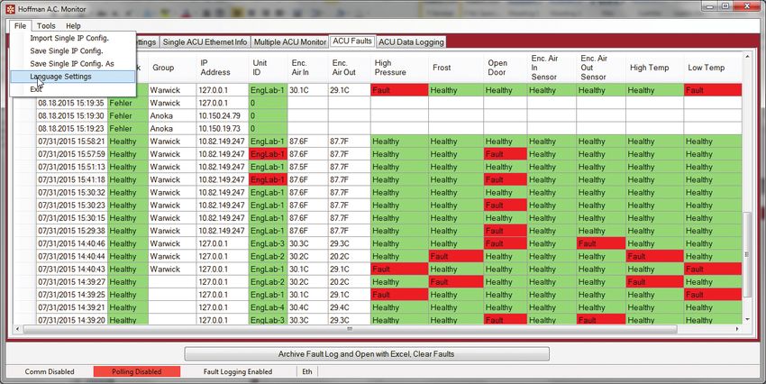
ALARM PARAMETERS
                    Parameter                   Description                Default Value                    Range
                       h24                     Device unit ID                    0                          0 to 4
                       h25                    Number of units                    4                          2 to 4

           NOTE 6: To initiate Primary-Secondary operating mode, set parameter h24 (device unit ID) of primary unit to 1. Set
           parameter h24 of secondary units as applicable. Set parameter h24 (unit number 2) to 2, set parameter h24 (unit
           number 3) to 3, and set parameter h24 (unit number 4) to 4.

           NOTE 7: Set parameter h25 (number of units) of each unit to the same value, for example, h25
           = 2 if only two units are connected in a group, h25 = 3 if three units are in a group and h25 = 4
           if four units are in a group.

89091001                                            © 2021 nVent                                                                -7-
PRIMARY-SECONDARY ALARM INPUT CONNECTION
The smart controller can accept a TLAN communication via the 6-POS connector terminals 5 and 6 marked PS1
and PS2 located on the enclosure side of the unit. This TLAN communication is associated with the controller
display alarm “LC” and “LC1”, lost communication.
To use the TLAN communication feature, simple connect the TLAN harness to PS1 and PS2 terminals and to PS1
and PS2 of each unit in parallel.

REMOTE ACCESS CONTROL
AIR CONDITIONER UNIT COMMUNICATION FEATURES
An optional communication board offers capabilities that include Profinet, EtherNet/IP, Modbus TCP, and SNMP
protocols through Ethernet and Modbus RTU protocol via USB. Hoffman® Cooling has a PC Interface Tool
available for download that can utilize either mode to communicate with the air conditioner unit.

      USB COMMUNICATION
      This communication mode allows direct connection of a PC to the air conditioner unit. The protocol
      supported is Modbus RTU. Use the PC Interface Tool to communicate with the air conditioner unit. A
      MINI-b USB connection is provided.

      ETHERNET COMMUNICATION
      This communication mode allows remote connection to the air conditioner unit using SNMP, Modbus
      TCP, EtherNet/IP, and Profinet protocols. Customers using their own software can download a MIB file for
      SNMP, Coil_Register file for Modbus TCP, EDS file or EtherNet_IP Object file for EtherNet/IP, and GSDML
      file for Profinet.
          NOTE: ACU has a default IP Address of 192.168.1.2

      Both Ethernet and USB communication modes allow the ability to:
      •   Read ACU inlet and outlet air temperatures
      •   Read and change Cooling Set-point and Cooling Differential
      •   Read and change Heating Set-point, Heating Differential
      •   Read and change High and Low Temperature Alarm Settings
      •   Read and change Gateway IP Address, Device IP Address, Subnet Mask, Trap IP Address and Community
      •   Read and change Unit Identification
      •   Read and change the state of IP addressing (static or dynamic)
      •   Read current Alarm Status
      •   Read MAC Address
      •   Read and change the door open and/or smoke detected switch polarity
      SOFTWARE AND CONFIGURATION FILE DOWNLOADS
      The PC Interface Tool, MIB file, EDS file, EtherNet_IP Object file and Coil_Register file can be downloaded
      from https://hoffman.nvent.com/en-us/remote-access-control.

      PRIMARY-SECONDARY CAPABILITY (OPTIONAL)
      In the primary-secondary application, only one Remote Access Communication board is required. All
      alarms are communicated through the TLAN serial connection, except the door open and/or smoke
      detected alarm. Door open and/or smoke detected switch polarity can be remotely changed from
      Normally Open to Normally Close if needed.
          Note that if the door open and/or smoke detected harness is not used, and the door switch is
          wired to only one of the units, for instance, the primary unit. If the power of the primary unit is
          OFF, the secondary units will NOT detect the door open alarm and they will continue operating
          in standalone mode even if the door is open.

   SOFTWARE AND CONFIGURATION FILE DOWNLOADS
The PC Interface Tool, MIB file, Coil_Register file, EDS file or EtherNet_IP Object file, and GSDML file can be
downloaded from https://hoffman.nvent.com/en-us/remote-access-control#resources
-8-                                          © 2021 nVent                                                         89091001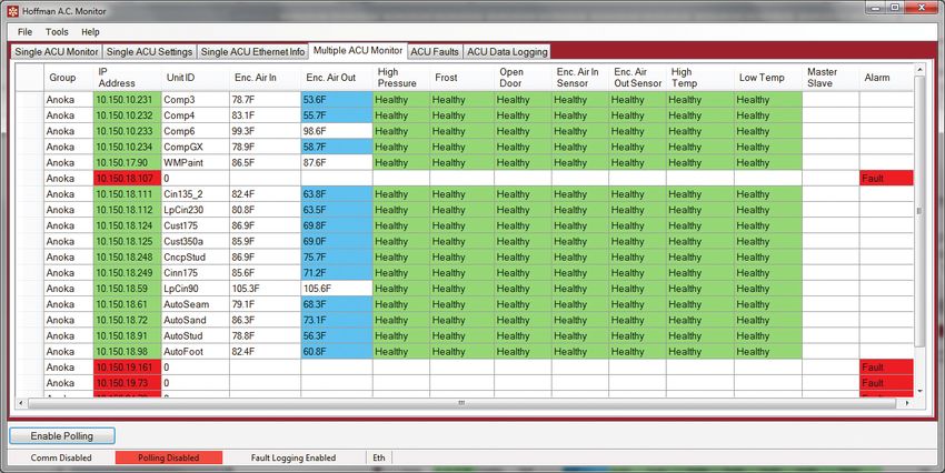
USING THE PC INTERFACE TOOL
The PC Interface Tool gives the user the ability to communicate with the air conditioner unit to read/write
parameters using either Ethernet or USB connections.

    USB COMMUNICATION MODE
           NOTE: Before connecting unit to the PC, make note of the comm ports present. After the unit
           is connected to the PC, a new comm port will be added to the list. Use this new comm port.

    •      From Tools menu select Use Ethernet
    •      When Use Ethernet is unchecked, then Comm Port menu is enabled, Device IP and Community boxes are not
           shown, and USB communication can be used
    •      To set the comm port, choose Comm Port from the Tools menu and then select the comm port from the combo box
    VIEWING AIR CONDITIONER UNIT VALUES
    To view Air Conditioner Unit values
    •      Select the ACU Values tab
    •      Select the Enable Comm button (the PC Interface will now be communicating with unit)
    •      To stop communication select the Disable Comm button
    CHANGING AIR CONDITIONER UNIT VALUES
    To change ACU Values
    •      Select the Settings tab
    •      Select the value to change
    •      Make the change to the value
    •      Select the Change Setting button
    •      Change can be verified in ACU Values tab
    VIEWING AND CHANGING ETHERNET INFORMATION
    To view and change Ethernet Information
    •      Select Ethernet Info tab
    To view Ethernet Information
    •      Click Read Ethernet Info button
    To change to dynamically assigning IP Address Mode
    •      Check Use DHCP Server checkbox
    •      Enter Trap IP Address and Community
    •      Click Load Ethernet Info button
    To change to statically assigning IP Address Mode
    •      Uncheck Use DHCP Server checkbox
    •      Enter Device IP Address, Subnet Mask, Gateway IP Address, Trap IP Address and Community
    •      Click Load Ethernet Info button
    ETHERNET COMMUNICATION MODE
           Each unit has two community strings. One is a Read/Write community string (defaulted to
           ‘private’) that can be changed by the customer (must be 4 to 8 characters long). The other is a
           Read-Only community string (‘public’) and cannot be changed.

89091001                                         © 2021 nVent                                                       -9-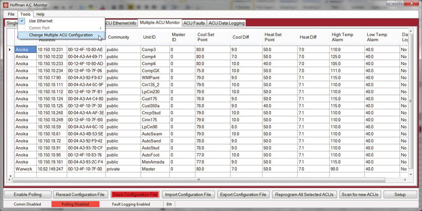
1. The Hoffman A.C. Monitor
            The Hoffman A.C. Monitor is a Windows® application for the complete management of Hoffman
            air conditioners. The initial air conditioner settings; cooling/heating set-points, cooling/heating
            differential and high/low temperature alarm set-points are pre-programmed at the factory, but
            can be locally or remotely adjusted by the user. Alarms are output from the air conditioner relay
            contacts and also can be accessed through an Ethernet network connection. A USB serial
            connection is provided on the air conditioner to configure the network interface and air conditioner
            settings before it is connected to a network.
             Windows is a registered trademark of Microsoft Corporation in the United States and/or other countries.
             When a Commboard is installed in a Hoffman air conditioner, it can communicate with an external
             computer or PLC using the SNMP, EtherNet/IP, Modbus TCP, and PROFINET protocols.
             1.1 New Features in V3.1.0
                 •   Support for Primary-Secondary ACU configurations, with one Primary ACU and up to three secondary ACUs.
                 •   Support for configuring the polarity of the door open/smoke detected switch with Control firmware version
                     11 or newer.
                 •   Added support for the Mexican Spanish language
         2. Installing the Hoffman A.C. Monitor
             Note: If you are upgrading from V3.0.3 or V3.0.4 to V3.0.5, the location where configuration
             files are stored has changed. You should follow the procedure in 4.6 Exporting a Configuration
             File on page 23 to export the configuration file to a local directory, upgrade the application,
             and then follow the procedure in 4.5 Importing a Configuration File on page 21 to import the
             original configuration file.

         •   Unzip the Hoffman A.C. Monitor 3.1.0 Setup.zip file into a temporary directory.
         •   Double click on the Hoffman A.C. Monitor 3.1.0 Setup.exe file to start the installation process.

         •   Click on the “Next” button when the installation window opens.

- 10 -                                                © 2021 nVent                                                     89091001
• If the default installation directory is OK click the “Next” button.
• By default, the installation will put the User’s Manual and the Serial USB driver in the C:\Users\\
Documents\Hoffman directory. If you don’t want the User’s Manual, uncheck the box. If it is OK, click the “Next”
button.
• If the default Start Menu folder “Hoffman” is OK, click the “Next” button.
89091001 © 2021 nVent - 11 -• Click the “Install” button to start the installation.
• Click on the “Finish” button when the installation completes.
• The Hoffman A.C. Monitor application is now ready to use. You can start the program by clicking “Start->All
Programs->Hoffman->Hoffman A.C. Monitor” menu, or on the Desktop icon.
- 12 - © 2021 nVent 890910013. Running the Hoffman A.C. Monitor
The installation program added an entry to the list of programs in the Windows “Start->All
Programs->Hoffman” menu, and added an icon on the Desktop.
Hoffman A.C. Monitor
Click on “Hoffman A.C. Monitor” in the “Start->All Programs->Hoffman” menu or double-click
on the “Hoffman A.C. Monitor” link on the Desktop to start the program. The program will
detect the default language for the PC and configure the program for English, German, Mexican
Spanish, Polish, Russian, or Simplified Chinese. If the PC is configured for any other language, the
application’s language will configure to English.
Note: If no air conditioners have been configured, a window will open stating that the
configuration file does not exist.
Click “OK” button to create empty configuration files and to close the window.
Note: If you exported a configuration file from a previous version of the application, now is
the time to import the original configuration file by follow the procedure in 4.5 Importing a
Configuration File on page 21.
The application will start with the “Single Hoffman A.C. Monitor” tab selected.
Click on the “Multiple Hoffman A.C. Monitor” tab to select the Multiple Hoffman A.C. Monitor
mode.
89091001 © 2021 nVent - 13 -Note: You will need to perform the configuration procedure or import a configuration file
before you can monitor multiple air conditioners. (See 4. Configuring the Hoffman A.C.
Monitor on page 16)
3.1 Controlling the Hoffman A.C. Monitor Display
When you click on the “Multiple A.C. Monitor” tab, the configuration file is read and the
corresponding air conditioners are displayed. You can click on the column headings to change the
sequence order of the air conditioners that are displayed and polled.
For example, if you added an air conditioner and want the air conditioners displayed in IP address
order, just click on the “IP Address” column header. The air conditioners will now be displayed
in increasing IP Address order. You will see an “up arrow” to the right of the “IP Address” that
indicates the increasing IP address order.
If you click on the “IP Address” column header again, the air conditioners will now be displayed
in decreasing IP Address order. You will see a “down arrow” to the right of the “IP Address” that
indicates the decreasing IP address order. The same procedure works with any column in the
display.
Note: You can click on the “Alarm” column header to display air conditioners with a fault
condition at the top of the list.
Note: If you would like the current display order to be permanent, Click on “Tools” menu, then
“Change Multiple ACU Configuration” in the pull-down menu, and, finally, click on the “Save
Configuration File” button.
- 14 - © 2021 nVent 890910013.2 Displaying ACU Faults
If “Alarm File Logging” is enabled, (See 6.1 Enabling Hoffman A.C. Monitor Auto-Start and/or
Alarm File Logging on page 26) and the Hoffman A.C. Monitor application detects an ACU fault,
the details of the fault(s) will be stored in an XML file.
The contents of the Alarm XML file can be displayed by clicking on the “ACU Faults” tab. The
default order is descending by date/time so the latest faults will be at the top of the list. You can
click on the column headings to change the order of the air conditioner faults display.
Note: If a new fault is logged when the “ACU Faults” tab is selected, the screen will refresh and
display all of the faults in descending date/time order.
89091001 © 2021 nVent - 15 -4. Configuring the Hoffman A.C. Monitor
After the Hoffman A.C. Monitor application has been started for the first time, you will need to
enter the network IP address of each air conditioner.
4.1 Scanning for New Air Conditioners
The Hoffman A.C. Monitor application can scan a Class-C network subnet for air conditioners that
are not currently configured. The application will poll each IP address on a network subnet. If it
finds an air conditioner that is not currently configured, it will add it to the configuration.
Click “Tools” menu and select “Change Multiple ACU Configuration” in the pull-down menu.
Note: The MAC Address displayed to the right of the IP address corresponds to the MAC
Address printed on the label on the air conditioner. You can use the MAC Address shown in
the A.C. Monitor to confirm that the IP address for a given air conditioner is correct.
Click the “Scan for new ACUs” button. A window will open where the Class-C network subnet to
scan can be entered.
- 16 - © 2021 nVent 89091001Enter the Class-C network subnet that contains the new air conditioners in dotted format and click
on the “Start” button. The last digit should be a “0” (zero). Any new air conditioner found will be
added to the configuration.
Note: You must save the configuration file to make the new air conditioners permanent.
Note: With the default network configuration, it takes approximately 4 seconds to poll
each possible IP address when looking for new air conditioners. There are 254 possible IP
addresses on a subnet, so it will take more than 15 minutes to scan a complete subnet. You
can reduce the default IP Retries to 1 by clicking on the down-arrow next to the IP Retries box,
and reduce the default IP Time out to shorten the scanning time.
Note: A future version of this application will allow the use of an arbitrary subnet mask.
Note: In a Primary/Secondary configuration the Primary ACU is the only ACU connected to the
network. The Primary ACU will be added to the configuration, but the Secondarys will not be
added. The Secondary ACUs will need to be manually added to the configuration.
4.2 Manually adding an air conditioner to the configuration
Click the “Tools” menu and select “Change Multiple ACU Configuration” from the pull-down menu.
89091001 © 2021 nVent - 17 -The asterisk“*” at the left of the empty row indicates that it is ready to edit the configuration. Click
once on the empty cell to the right of the asterisk “*” and below the “Group” heading to select
the cell. Enter the name of the Group for this air conditioner. The Group can be used to organize
the air conditioners by geographic location, plant, work cell, etc. The Group can be any text; for
example, Anoka, Welding, Router, etc. As you enter the Group you will see a “pencil” icon at the
left of the row. When you have finished entering the Group, press the “Tab” key. The “pencil” icon
will change to a triangle and the “IP Address” cell will be highlighted. Click on the “IP Address” cell
to allow text editing. Enter the IP address for the air conditioner in “dotted” format, for example
“10.82.149.247”. When you have finished entering the IP address, press the “Tab” key twice and
the “Community” cell will be highlighted. Click on the “Community” cell to allow text editing. If
the SNMP Community is set to “public” the sensors and alarms can be read, but configuration
changes to the air conditioner controller will not be allowed. The factory default value for the
SNMP Community can be changed in the air conditioner to another value to improve security. If
you plan to use the Hoffman A.C. Monitor application to make configuration changes to the air
conditioner controllers, you will need to set the SNMP Community to the factory default value of
“private”, or to the customized value. When you have finished entering the Community, press the
“Enter” key.
- 18 - © 2021 nVent 89091001For a Primary-Secondary configuration, each ACU in the Primary-Secondary set will need to be
configured separately. When you add an ACU, the Primary ID will default to 0 to indicate that it
is a standalone ACU. You will need to change the Primary ID to a 1 for the Primary ACU. When
you add a Secondary ACU, use the same IP address as the Primary ACU, but change the Primary
ID to correspond to the Secondary ACUs ID in the range of 2-4. When the ACUs are polled, the
application will append the Primary/Secondary ID to the Unit ID to make tracking easier.
The Hoffman A.C. Monitor application screen should look like the image above. Click the “Save
Configuration File” button to save the current air conditioner configuration.
Click the “Yes” button to save the current Hoffman A.C. Monitor configuration.
Repeat the above steps to add additional air conditioners to the configuration.
89091001 © 2021 nVent - 19 -4.3 Deleting an air conditioner from the configuration
Click the “Tools” menu and select “Change Multiple ACU Configuration” from the pull-down menu.
Click the box to the left of the row for the desired air conditioner. All cells in the row will highlight.
Press the “Delete” key.
Click the “Yes” button to confirm deletion of the air conditioner. Click the “Save Configuration File”
button to save the current air conditioner configuration.
Click the “Yes” button to save the current air conditioner configuration.
Repeat the above steps to delete more air conditioners from the configuration.
Note: You can hold the “CTRL” key on your keyboard down and click on multiple ACUs. When
you press the “Delete” key the application will ask if it is OK to delete each of the selected air
conditioners.
4.4 Modifying the air conditioner settings
When you enable polling of the air conditioners for the first time, the Hoffman A.C. Monitor
application will determine that the Unit ID, Cooling Set-Point, Cooling Differential, Heating Set-
Point, Heating Differential, High Temperature Alarm and Low Temperature Alarm settings in the
configuration file are empty. The application will obtain the current values from the air conditioner
and populate the configuration file. To populate these fields, you can click on the “Enable Polling”
button, wait for it to cycle through all of the air conditioners, click the “Disable Polling” button,
- 20 - © 2021 nVent 89091001click the “Tools” menu and select “Change Multiple ACU Configuration” from the pull-down menu,
and, finally, click the “Save Configuration File” button to save the configuration values from the air
conditioners.
If you need to change any of the air conditioner set-points, you can click the “Tools” menu and
select “Change Multiple ACU Configuration” from the pull-down menu, click twice on a cell in the
configuration display, change the value, and select “Save Configuration File” button. To reprogram
the set-points in the air conditioner, click on the box to the left of the “Group” cell for the desired air
conditioner, and select “Reprogram All Selected ACUs” button. If you would like to reprogram more
than one air conditioner at a time, you can hold the “CTRL” key down while you select more than
one air conditioner controller. Clicking on the “Configure All Selected ACUs” button will reprogram
all of the selected air conditioners.
Note: If the air conditioner does not respond to the reprogramming commands, the IP address
cell will be highlighted in red. If an individual setting cannot be reprogrammed, the settings
cell will be highlighted in red.
Note: If the SNMP Community is set to “public”, you cannot change the settings of an air
conditioner. The SNMP Community must be set to the same value as the air conditioner is
programmed. The factory default value is “private”.
Note: The IP address and SNMP Community settings cannot be changed from the Multiple
Hoffman A.C. Monitor tab. You can use the Single ACU Ethernet Info tab to change the IP
address or SNMP Community settings.
4.5 Importing a Configuration File
An existing XML configuration file can be imported into the Hoffman A.C. Monitor.
89091001 © 2021 nVent - 21 -Click the “Tools” menu and select “Change Multiple ACU Configuration” from the pull-down menu.
and, finally, click “Import Configuration File” button.
Use the “Open Multiple ACU Configuration File” window to find and select the XML configuration
file to import, and select “Open” button. You must click the “Save Configuration File” button to
make the imported configuration the permanent configuration.
- 22 - © 2021 nVent 890910014.6 Exporting a Configuration File
The current Hoffman A.C. Monitor configuration can be exported to an XML file.
Click the “Tools” menu and select “Change Multiple ACU Configuration” from the pull-down menu.
Then click “Export Configuration File” button.
From the “Open Multiple ACU Configuration File” window, select the desired directory and file
name and click “Save” button.
Note: The default directory for saving the configuration file is C:\Users\\
Documents\Hoffman.
Click “Yes” to save the configuration file.
Note: You can use the Export/Import tools to copy the Multiple ACU Configuration from one PC
to another.
Note: You can export the Multiple ACU Configuration file, edit it using an XML editor, and,
finally, re-import it.
89091001 © 2021 nVent - 23 -4.7 Changing the ACU IP Address or SNMP Community Setting
Click on the box to the left of the row containing the IP address for the air conditioner. The row will
be highlighted and the IP Address and SNMP Community will be set in the corresponding fields
in the Single Hoffman A.C. Monitor tab. These fields will be used to communicate with the air
conditioner.
Click on the Single ACU Ethernet Info tab. Click on the “Read Ethernet” info button. The current
Ethernet configuration will be displayed. Edit the fields as desired and click “Reprogram ACU”
button. The updated network configuration will re-program the air conditioner.
Note: The IP address and SNMP Community settings cannot be changed from the Multiple
Hoffman A.C. Monitor tab. You can use the Single ACU Ethernet Info tab to change the IP
address or SNMP Community settings.
Note: You will need to modify the configuration in the Multiple Hoffman A.C. Monitor tab to
correspond to the new network configuration for the air conditioner.
- 24 - © 2021 nVent 890910015. Monitoring or Configuring a Single ACU
The Hoffman A.C. Monitor can monitor and configure a single ACU through the network
connection.
5.1 Monitoring a Single ACU
To monitor a single ACU, click on the “Single ACU Monitor” tab. Enter the IP Address of the ACU
in the “Device ID” field and click on the “Enable Comm” button. The text on the “Enable Comm”
button will change to “Disable Comm” when communications with the ACU is established. Click on
the “Disable Comm” button to stop monitoring a single ACU.
The Standalone or Primary ACU information will be displayed on the left side of the window. If the
ACU is a Primary in a Primary/Secondary configuration, a window on the right will open for each
Secondary ACU. ACU faults will be shown as text messages in the “Faults” window.
5.2 Configuring a Single ACU
To configure a single ACU, click on the “Single ACU Monitor” tab. Enter the IP Address of the ACU
in the “Device ID” field, and enter the SNMP Community in the “Community” field. The default
SNMP Community of “public” will not allow ACU configuration changes to be made. The default
SNMP Community of “private” will allow configuration changes, but it is likely that this default
SNMP Community ID was changed when the ACU was installed.
Click on the “Single ACU Settings” tab to open the ACU configuration window. Click on the “Read
Settings” button to read the current configuration from the ACU. Change the desired field in the
window, and click in the corresponding checkbox (square) to enable changing, and click on the
“Change Settings” button.
The Primary/Secondary configuration and the Door Switch Polarity can be changed using the
same method.
Note: the Temperature setpoints can only be changed in 0.1 degree steps. There is an upper and
lower limit to all of the temperature settings.
89091001 © 2021 nVent - 25 -6. Hoffman A.C. Monitor Auto-Start and Alarm File Logging
The Hoffman A.C. Monitor can be configured to automatically start polling the air conditioners in
the Multiple ACU mode when the application is started, and/or to enable logging of faults into an
alarm file.
6.1 Enabling Hoffman A.C. Monitor Auto-Start and/or Alarm File Logging
- 26 - © 2021 nVent 89091001To enable Hoffman A.C. Monitor Auto-Start or Alarm File Logging, click the “Tools” menu, select
“Change Multiple ACU Configuration” from pull-down menu and click Setup button.
Select Enable Alarm File Logging check box and/or the Multiple Hoffman A.C. Monitor Auto-Start
check box and click OK button.
6.2 Exporting the Alarm File to Microsoft Excel
If you click on the “ACU Faults” tab and select “Archive Fault Log and Open with Excel, Clear
Faults” button, the Hoffman A.C. Monitor will copy the fault log file into a new XML archive file. The
new XML archive fault log file will be located in the “Hoffman” directory in your local documents
directory. The name of the file will be as shown here MMDDYYY-hhmmmssACUAlarm.xml where
MMDDYYY is the current month/day/year and hhmmss is the 24 hour version of the current time.
If Excel is installed, Excel will be launched to open the XML archive fault log file. The current faults
in the display will be cleared. The Alarm File is XML formatted and can be read by Microsoft Excel.
89091001 © 2021 nVent - 27 -A window will open as shown above. Click OK button.
A window will open as shown above. Click OK button.
The image above shows an example of the imported alarm file. Each row represents a change
in the network connection state or a change in the alarm state for one ACU. The date and time
from the PC running the Hoffman A.C Monitor at the time of the fault is listed in column A. If the
Network column contains Fault, the ACU did not respond to an SNMP poll, but had previously
responded. The group that was assigned to the ACU is listed in column C, and the IP and MAC
address of the ACU are in columns D and E respectively. Columns G and H contain the inlet and
outlet temperatures when the fault occurred. The remaining columns show the state of the ACU
alarms when the fault occurred.
For example, row 9 shows an ACU that failed to respond to an SNMP poll, but had previously
responded. Row 2 shows a high pressure fault and row 4 shows a door open fault.
- 28 - © 2021 nVent 890910017. Changing the Hoffman A.C. Monitor Language
The Hoffman A.C. Monitor is multilingual. When the application is started, it will detect the native
language configured in Windows and set the application’s language to English, German, Mexican Spanish,
Polish, Russian, or Simplified Chinese. If the PC is configured for any other language, the application’s
language will configure to English.
7.1 Overriding the detected language setting
You can override the detected language by clicking “File”and selecting “Language Settings”.
A window will open as shown above. Select “Manually Configure Language” button. A pull-down
menu will be displayed showing the possible languages. Select the desired language and click
“OK”.
89091001 © 2021 nVent - 29 -8. Hoffman A.C. Monitor Data Logging
The Hoffman A.C. Monitor can be configured to log sensor data from one or more ACUs into a sensor
data file. The sensor data file can then be opened in Excel for analysis.
8.1 Configuring an ACU for Data Logging
To configure an ACU for data logging, click “Tools” menu and select “Change Multiple ACU
Configuration” from the pull-down menu. Then click Setup button.
Find the ACU you would like to configure, click on the “Data Logging” column cell to change the
“No” to “Yes”, and, finally, click “Save Configuration File”. Repeat this for each ACU that you would
like to configure an ACU for data logging.
When clicking on “Enable Polling” button, the sensor data for each ACU that was configured for
data logging will be stored in an XML file.
- 30 - © 2021 nVent 890910018.2 Exporting the Sensor Data to Microsoft Excel
If the “ACU Data Logging” tab is selected and “Archive Data Log and Open with Excel, Clear
Log” button is clicked on, the Hoffman A.C. Monitor will copy the data log file into a new
archive file. The new archive fault log file will be located in the “Hoffman” directory in your
local documents directory. The name of the file will be formatted as shown here MMDDYYY-
hhmmmssACUDataLog.xml where MMDDYYY is the current month/day/year and hhmmss is
the 24 hour version of the current time. If Excel is installed, Excel will be launched to open the
archive data log file. The current sensor data in the display will be cleared. The data log file is XML
formatted and can be read by Microsoft Excel.
A window will open as shown above. Click OK button.
A window will open as shown above. Click OK button.
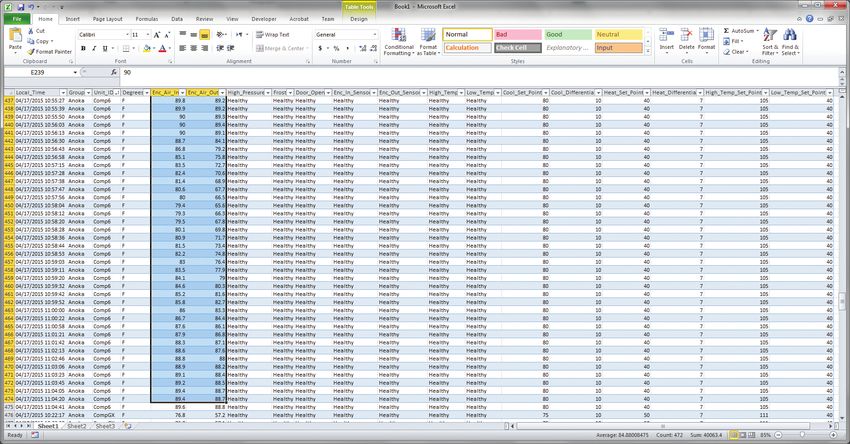
89091001 © 2021 nVent - 31 -The image above shows an example of the imported data log file. Each row represents sensor
data for one ACU. The date and time from the PC running the Hoffman A.C Monitor at the time
of the poll is listed in column A. You can sort the data by clicking on the arrow next to the column
heading.
8.3 Graphing the Temperature Sensor Data in Microsoft Excel
In order to create a temperature sensor graph, click on the Unit ID arrow to sort all of the data for
each ACU into adjacent cells. Select the Enc_Air_In and Enc_Air_Out cells for a single ACU. Click
on “Insert”, “Line”, and select the 2D Line chart.
- 32 - © 2021 nVent 89091001The resulting chart showing the Inlet Air Temperature and the Outlet Air Temperature will appear
as shown above.
To change the Legend for the sensor readings, click on the legend at the right side of the chart,
right click and click on“Select Data”. Then click on “Series 1”, click on “Edit”, enter “Inlet Air” in text
box, and click “OK”. Repeat for “Series 2” and name it “Outlet Air”.
To add a title to the Y-Axis of the chart, click on the chart, click on “Layout”, click on “Axis Titles”,
click on “Primary Vertical Axis Title”, and, finally, click on “Rotated Title”. A text box will appear to
the left of the numbers. Click on the text and change it to “Degrees F”.
If a title on the top of the chart is desired, click on the chart, click on “Layout”, click on “Chart Title”,
click on “Above Chart”. A text box will appear above the chart. Click on the text and change it to
“Compressor 6”.
The above resulting chart had the ACU Cooling Setpoint set to 80F and the Cooling Differential set
to 10F. From this graph, one can see that the corresponding Inlet Temperature varied between 80F
and 90F.
89091001 © 2021 nVent - 33 -INSTRUCTIONS FOR CONFIGURING EMAIL OR SMS WHEN THERE IS AN ACU FAULT
1. Install the V3.1.1 ACU monitor.
2. Copy the ACUconfig.xml from the email to the “My Documents/Hoffman” directory.
3. Execute Hoffman A.C Monitor SW
4. Click on “Tools” then “change Multiple ACU Configuration” then “Import Configuration File”.
- 34 - © 2021 nVent 890910015. When the window opens, select the ACUconfig.xml file and click on the “Open” button.
6. When the window closes, click on the “Save Configuration File” button.
7. When the window opens, click on the “OK” button.
8. To add new A/C from the network, click the new cell of “Group” and then enter the name of the A/C
unit
89091001 © 2021 nVent - 35 -9. Press “Tap” key to move to “IP Address” cell and it will be highlighted. Click on the “IP Address”
cell and enter the desire IP Address
10. After completed entering the IP Address, press “Tap” key 12 times.
11. Click on “Email” cell and enter the email or phone number of the technician services personnel
who is responsible to this specific A/C unit. For example, for email: %shawn.thao@pentair.com
and/or for text: %7632031233@txt.att.net . In this case the phone carrier is AT&T.
12. Click “Save Configuration File” after completed configuration
13. Click on the “Enable Polling” button.
You will get an email when the ACU Monitor detects a fault, or the faults go away.
To change from receiving an email to receiving an SMS, click on “Tools” then “change Multiple
ACU Configuration”. Slide the scroll bar at the bottom of the screen to the right so you can see the
email addresses. Now it gets a little complicated.
You need to enter an email address that includes a “%” at the beginning to force the message to
English, then your 10 digit phone number, then the host name for the gateway service for your
phone carrier. If your mobile is with AT&T, it is likely “%7632031233@txt.att.net”. If you have
Verizon for your carrier then “%7632031233@vtext.com”.
When you are finished, click on “Save Configuration File” then “Enable Polling”
- 36 - © 2021 nVent 890910011. Sending An Email Or SMS When An ACU Fault Is Detected.
The Hoffman A.C. Monitor can be configured to send an email when an ACU fault is detected
and when all of an ACU’s faults are cleared. The email contains identifying information for the
ACU, the inlet and exhaust air temperatures, and a list of the faults. An individual email address is
configured for each ACU so the person responsible for servicing that ACU gets the fault email. The
email will be in the language that is configured for the Hoffman A.C. Monitor.
Many cell telephone carriers provide a gateway that will forward an email to a cell telephone as
a text (SMS) message. Unfortunately many of the cell telephone carriers’ email gateways do
not handle international characters well, so you may need to force to the email to be sent in the
English language. To send the ACU fault message as a text message, you need to enter an email
address that includes a “%” at the beginning if you want to force the message to English, then
your 10 digit cell telephone number, then the host name for the SMS gateway service for your cell
telephone carrier. If you want to try the text message in a language other than English, just leave
the “%” off of the beginning of the cell telephone number.
If your cell telephone carrier is:
• China Mobile, then the email address would be “%7635551212@139.com”
• Orange, then the email address would be “%7635551212@orange.net”
• T-Mobile, then the email address would be “%7635551212@tmomail.net”
• AT&T, then the email address would be “%7635551212@txt.att.net”
• Verizon, then the email address would be “%7635551212@vtext.com”
Note: Most cell telephone carriers provide a text message gateway. If your cell telephone
carrier is not listed above, contact your cell telephone carrier for the text message gateway
address.
Before you can send an email or text message, you need to configure the Hoffman A.C. Monitor
with the SMTP email server for your company. (You may need some help from your IT department
with this part.)
Open the Hoffman A.C. Monitor application, click on “Tools” then “Change Multiple ACU
Configuration” and then click on the “Setup” button.
Fault Logging needs to be enabled in order to send an email or text message when an ACU fault is
detected. Enabling “Email on Fault” will enable Fault Logging. Click on the checkbox to the left of
“Email on Fault” to enable sending an email or text message.
Enter the SMTP email server’s host name for your company in the “SMTP Server” field.
Enter the SMTP email server’s port number in the “SMTP Port” field. The SMTP email server’s port
number is usually 25, but may be different.
89091001 © 2021 nVent - 37 -Enter the email address that you would like in the “From:” field of the ACU Fault email in the
“SMTP From” field. The “SMTP From” email address may need to be a valid email address on your
company’s SMTP server.
If your company’s SMTP email server requires authentication, click on the checkbox for “Use
SMTP Authentication” and enter a valid “SMTP User Name” and “SMTP Password” in the fields.
If your company’s SMTP email server requires encryption, click on the checkbox for “Use SSL/
TLS”.
When you are finished, click on the “OK” button, then click on the “Save Configuration File” button.
Slide the scroll bar near the bottom of the screen to the right to show the fields for the email
address. Enter the email address for each ACU, then click on the “Save Configuration File” button.
When you click on the “Enable Polling” button the Hoffman A.C. Monitor will look for ACU faults,
and send an email when a fault is detected, or all faults are cleared. If there are any configuration
errors with the SMTP email server when the Hoffman A.C. Monitor tries to send a fault email, you
will see a popup window describing the problem. Correct the SMTP configuration problem, and
then enable polling.
- 38 - © 2021 nVent 89091001NOTES 89091001 © 2021 nVent - 39 -
BASIC AIR CONDITIONING TROUBLE SHOOTING CHECK LIST - REMOTE ACCESS
CONTROL VERSION
         1. Check manufacturer’s nameplate located on the unit for correct power supply.
         2. Turn on power to the unit. The controller will display a start up sequence then revert to the normal
            temperature display mode. Is the correct enclosure temperature displayed?
           Note: The temperature may be alternating with an alarm code.

            YES, proceed to step 3.
            NO, possible problem:
            »» Open controller fuse
            »» Controller in alarm condition..
            »» Defective controller                                                     Replace part
            »» Defective thermistor - check by blowing
               warm air across the thermistor. If display
               temperature rises, thermistor is operable.

         3. The cooling status indication (symbol G) should be on. Is the symbol on? If not, press and hold the
            lower right “snowflake” button for greater than five seconds. Is the cooling mode symbol now on?
            YES, proceed to step 4.
            NO, possible problem:

            »» Defective controller                                                    Replace part

         4. The evaporator (Enclosure or “COLD” air) fan/impeller should turn on. Is there airflow?
            YES, proceed to step 5.
            NO, possible problem:
            »» Controller in alarm condition.
            »» Open motor winding
                                                                                      Repair or Replace
            »» Stuck fan/impeller                                                      defective part
            »» Obstructed blades/wheel
            »» Defective motor capacitor

         5. Start the cooling cycle by changing the cooling setpoint parameter (r01) to the low limit of 72 F (22
            C). Symbol 1 should be displayed indicating a call for cooling. If symbol 1 is flashing, the unit is in
            Restart Time Delay mode. Within 6 minutes, symbol 1 should display without flashing. Is symbol 1
            displayed without flashing?
            YES, proceed to step 8.
            NO, possible problem:

            »» Unit still in Restart Time Delay mode
            »» Enclosure temperature below cooling                                     Wait and/or heat
                                                                                    enclosure thermistor T1
               setpoint temperature

         6. The compressor and the condenser (Ambient or “HOT” air) impeller(s) should turn on. Is there
            adequate airflow?
            YES, proceed to step 7.
            NO, possible problem:
            »» Open motor winding(s)
            »» Stuck impeller(s)                                                    Repair or Replace
            »» Obstructed wheel(s)                                                   defective part

            »» Defective motor capacitor(s)

- 40 -                                            © 2021 nVent                                                        89091001
You can also read