Prodigyr High-Capacity HDLVr Powder Transfer Pump with Electric Timing Valve - Prodigy High-Capacity HDLV Powder Transfer ...
←
→
Page content transcription
If your browser does not render page correctly, please read the page content below
Prodigyr High-Capacity
                      HDLVr Powder Transfer Pump with
                           Electric Timing Valve
                                       Customer Product Manual
                                           Part 1619979-01
                                             Issued 1/21

        For parts and technical support, call the
 Finishing Customer Support Center at (800) 433-9319.
       This document is subject to change without notice.
Check http://emanuals.nordson.com/finishing for the latest version.

       NORDSON CORPORATION • AMHERST, OHIO • USA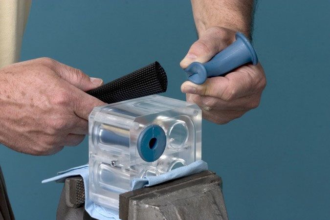
Table of Contents

Safety . . . . . . . . . . . . . . . . . . . . . . . . . . . . . . . . . . . . . . .    1   Maintenance . . . . . . . . . . . . . . . . . . . . . . . . . . . . . . . .           13
   Qualified Personnel . . . . . . . . . . . . . . . . . . . . . . . . .                1   Troubleshooting . . . . . . . . . . . . . . . . . . . . . . . . . . . . .             14
   Intended Use . . . . . . . . . . . . . . . . . . . . . . . . . . . . . .             1      Prodigy Electric Control Timing Valve Kit . . . . . .                              16
   Regulations and Approvals . . . . . . . . . . . . . . . . . .                        1   Repair . . . . . . . . . . . . . . . . . . . . . . . . . . . . . . . . . . . . . .    20
   Personal Safety . . . . . . . . . . . . . . . . . . . . . . . . . . . .              1      Fluidizing Tube Replacement . . . . . . . . . . . . . . . .                        20
   Fire Safety . . . . . . . . . . . . . . . . . . . . . . . . . . . . . . . .          2      Pump Disassembly . . . . . . . . . . . . . . . . . . . . . . . . .                 21
   Grounding . . . . . . . . . . . . . . . . . . . . . . . . . . . . . . . . .          2      Pump Assembly . . . . . . . . . . . . . . . . . . . . . . . . . . .                23
   Action in the Event of a Malfunction . . . . . . . . . . .                           2      Pinch Valve Replacement . . . . . . . . . . . . . . . . . . .                      26
   Disposal . . . . . . . . . . . . . . . . . . . . . . . . . . . . . . . . . .         2         Pinch Valve Removal . . . . . . . . . . . . . . . . . . . .                     26
Description . . . . . . . . . . . . . . . . . . . . . . . . . . . . . . . . . .         3         Pinch Valve Installation . . . . . . . . . . . . . . . . . . .                  27
   High-Capacity HDLV Pump Components . . . . . .                                       4      Tubing Diagrams . . . . . . . . . . . . . . . . . . . . . . . . . . .              28
   Theory of Operation . . . . . . . . . . . . . . . . . . . . . . . .                  6   Parts . . . . . . . . . . . . . . . . . . . . . . . . . . . . . . . . . . . . . . .   31
      Pumping . . . . . . . . . . . . . . . . . . . . . . . . . . . . . . .             6      Using the Illustrated Parts List . . . . . . . . . . . . . . .                     31
      Purging . . . . . . . . . . . . . . . . . . . . . . . . . . . . . . . .           7      Pump Assembly . . . . . . . . . . . . . . . . . . . . . . . . . . .                32
   Specifications . . . . . . . . . . . . . . . . . . . . . . . . . . . . . .           8      Pump Assembly without Controls . . . . . . . . . . . . .                           34
      Approval Label . . . . . . . . . . . . . . . . . . . . . . . . . .                9      Pump Controls . . . . . . . . . . . . . . . . . . . . . . . . . . . . .            36
Installation . . . . . . . . . . . . . . . . . . . . . . . . . . . . . . . . . .       10         Left Side . . . . . . . . . . . . . . . . . . . . . . . . . . . . . . .         36
Operation . . . . . . . . . . . . . . . . . . . . . . . . . . . . . . . . . . .        11         Right Side . . . . . . . . . . . . . . . . . . . . . . . . . . . . . .          38
   Pump with Generator . . . . . . . . . . . . . . . . . . . . . . .                   11      Powder and Air Tubing . . . . . . . . . . . . . . . . . . . . . .                  40
   Pump without Generator . . . . . . . . . . . . . . . . . . . .                      11      Spare Parts . . . . . . . . . . . . . . . . . . . . . . . . . . . . . . .          41

Contact Us                                                                                  Notice
Nordson Corporation welcomes requests for information, comments, and                        This is a Nordson Corporation publication which is protected by copyright.
inquiries about its products. General information about Nordson can be                      Original copyright date 2021. No part of this document may be
found on the Internet using the following address:                                          photocopied, reproduced, or translated to another language without the
http://www.nordson.com.                                                                     prior written consent of Nordson Corporation. The information contained
Address all correspondence to:                                                              in this publication is subject to change without notice.
        Nordson Corporation                                                                 Trademarks
        Attn: Customer Service
        555 Jackson Street                                                                  HDLV, Prodigy, Nordson, and the Nordson logo are registered trademarks
        Amherst, OH 44001                                                                   of Nordson Corporation.

 Part 1619979-01                                                                                                                                  E 2021 Nordson Corporation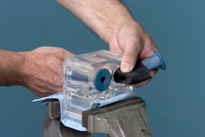
Change Record         i

Change Record
 Revision             Date                                      Change
   01                  1/21     Release of pump with electric timing valve.

   E 2021 Nordson Corporation                                                         Part 1619979-01
ii      Change Record

Part 1619979-01         E 2021 Nordson Corporation
Prodigy Generation II High-Capacity HDLV Pump          1

Prodigy Generation II High-Capacity HDLV Pump

Safety
Read and follow these safety instructions. Task-        Regulations and Approvals
and equipment-specific warnings, cautions, and
instructions are included in equipment                  Make sure all equipment is rated and approved for
documentation where appropriate.                        the environment in which it is used. Any approvals
                                                        obtained for Nordson equipment will be voided if
Make sure all equipment documentation, including        instructions for installation, operation, and service
these instructions, is accessible to all persons        are not followed.
operating or servicing equipment.
                                                        All phases of equipment installation must comply
Qualified Personnel
                                                        with all federal, state, and local codes.
Equipment owners are responsible for making sure
that Nordson equipment is installed, operated, and
serviced by qualified personnel. Qualified              Personal Safety
personnel are those employees or contractors who
are trained to safely perform their assigned tasks.     To prevent injury follow these instructions.
They are familiar with all relevant safety rules and    S Do not operate or service equipment unless you
regulations and are physically capable of                  are qualified.
performing their assigned tasks.
                                                        S Do not operate equipment unless safety
Intended Use                                               guards, doors, or covers are intact and
Use of Nordson equipment in ways other than                automatic interlocks are operating properly. Do
those described in the documentation supplied with         not bypass or disarm any safety devices.
the equipment may result in injury to persons or        S Keep clear of moving equipment. Before
damage to property.                                        adjusting or servicing any moving equipment,
Some examples of unintended use of equipment               shut off the power supply and wait until the
include                                                    equipment comes to a complete stop. Lock out
                                                           power and secure the equipment to prevent
S using incompatible materials                             unexpected movement.
S making unauthorized modifications                     S Relieve (bleed off) hydraulic and pneumatic
S removing or bypassing safety guards or                   pressure before adjusting or servicing
   interlocks                                              pressurized systems or components.
S  using incompatible or damaged parts                     Disconnect, lock out, and tag switches before
                                                           servicing electrical equipment.
S using unapproved auxiliary equipment
S operating equipment in excess of maximum
   ratings

E 2021 Nordson Corporation                                                                       Part 1619979-01
2 Prodigy Generation II High-Capacity HDLV Pump

S Obtain and read Material Safety Data Sheets            Grounding inside and around the booth openings
   (SDS) for all materials used. Follow the              must comply with NFPA requirements for Class 2,
   manufacturer’s instructions for safe handling         Division 1 or 2 Hazardous Locations. Refer to
   and use of materials, and use recommended             NFPA 33, NFPA 70 (NEC articles 500, 502, and
   personal protection devices.                          516), and NFPA 77, latest conditions.
S To prevent injury, be aware of less-obvious            S All electrically conductive objects in the spray
   dangers in the workplace that often cannot be            areas shall be electrically connected to ground
   completely eliminated, such as hot surfaces,             with a resistance of not more than 1 megohm
   sharp edges, energized electrical circuits, and          as measured with an instrument that applies at
   moving parts that cannot be enclosed or                  least 500 volts to the circuit being evaluated.
   otherwise guarded for practical reasons.
                                                         S Equipment to be grounded includes, but is not
                                                            limited to, the floor of the spray area, operator
Fire Safety                                                 platforms, hoppers, photoeye supports, and
To avoid a fire or explosion, follow these                  blow-off nozzles. Personnel working in the
instructions.                                               spray area must be grounded.
                                                         S There is a possible ignition potential from the
S Do not smoke, weld, grind, or use open flames             charged human body. Personnel standing on a
   where flammable materials are being used or              painted surface, such as an operator platform,
   stored.                                                  or wearing non-conductive shoes, are not
S Provide adequate ventilation to prevent                   grounded. Personnel must wear shoes with
   dangerous concentrations of volatile materials           conductive soles or use a ground strap to
   or vapors. Refer to local codes or your material         maintain a connection to ground when working
   SDS for guidance.                                        with or around electrostatic equipment.
S Do not disconnect live electrical circuits while       S Operators must maintain skin-to-handle contact
   working with flammable materials. Shut off               between their hand and the gun handle to
   power at a disconnect switch first to prevent            prevent shocks while operating manual
   sparking.                                                electrostatic spray guns. If gloves must be
S Know where emergency stop buttons, shutoff                worn, cut away the palm or fingers, wear
   valves, and fire extinguishers are located. If a         electrically conductive gloves, or wear a
   fire starts in a spray booth, immediately shut off       grounding strap connected to the gun handle or
   the spray system and exhaust fans.                       other true earth ground.

S Clean, maintain, test, and repair equipment            S Shut off electrostatic power supplies and
   according to the instructions in your equipment          ground gun electrodes before making
   documentation.                                           adjustments or cleaning powder spray guns.

S Use only replacement parts that are designed           S Connect all disconnected equipment, ground
   for use with original equipment. Contact your            cables, and wires after servicing equipment.
   Nordson representative for parts information
   and advice.                                           Action in the Event of a Malfunction

Grounding                                                If a system or any equipment in a system
                                                         malfunctions, shut off the system immediately and
                                                         perform the following steps:
            WARNING: Operating faulty
            electrostatic equipment is hazardous and     S Disconnect and lock out electrical power. Close
            can cause electrocution, fire, or               pneumatic shutoff valves and relieve pressures.
            explosion. Make resistance checks part
            of your periodic maintenance program. If     S Identify the reason for the malfunction and
            you receive even a slight electrical shock      correct it before restarting the equipment.
            or notice static sparking or arcing, shut
            down all electrical or electrostatic         Disposal
            equipment immediately. Do not restart
            the equipment until the problem has          Dispose of equipment and materials used in
            been identified and corrected.               operation and servicing according to local codes.

Part 1619979-01                                                                          E 2021 Nordson Corporation
Prodigy Generation II High-Capacity HDLV Pump       3

Description
The Prodigy High-Capacity HDLV (High-Density
powder, Low-Volume air) powder pump transports
large amounts of powder from one location to
another.

The pump design and the small diameter suction
and delivery tubing used with the pump allow it to
be purged quickly and thoroughly.

The pump is more efficient than traditional
venturi-style pumps in that very little of the air that
is used to operate the pump is mixed into the
powder stream. Only the air that is used to move
the powder out of the pump and into the delivery
tubing enters the powder stream.

NOTE: Two versions of the pump are available.
One with a generator and one without. All images
shown in manual reference the pump with
generator.

                                                           Figure 1   Prodigy High-Capacity HDLV Pump

E 2021 Nordson Corporation                                                                       Part 1619979-01
4 Prodigy Generation II High-Capacity HDLV Pump

High-Capacity HDLV Pump Components
See Figure 2.
    Item                   Description                                      Function
Air Control Components
      1           Fluidizing Tube Control Valve   Cycles to alternate positive and negative air pressure to the
                                                  fluidizing tubes.
      2           Pinch Valve Control Valve       Cycles to switch the pinch pressure between the pinch
                                                  valves in each pump halves.
      3           Conveying Air Regulator and     Regulates the positive and negative air pressure being
                  Gauge                           applied to the fluidizing tubes. Typically set to 0.7−1.0 bar
                                                  (10−15 psi).
      4           Exhaust Muffler                 Allows the pump’s operating air to silently exit the pump.
      5           Turbine Generator               Uses compressed air to generate 24 Vdc for the electrically
                                                  controlled timing valve.
      6           Input Air Fitting               Connects the high-capacity HDLV pump to a 4.8−6.2 bar
                                                  (70−90 psi) air source.
      7           Pinch Pressure Regulator        Regulates the air pressure being applied to the pinch
                  and Gauge                       valves. Typically set to 2.4−2.75 bar (35−40 psi).
      8           Vacuum Generator                Works on the venturi principle to generate the negative air
                                                  pressure required to draw powder into the fluidizing tubes.
      9           Timing Control Valve            Controls the fluidizing tube control valve and pinch valve
                                                  control valve operating sequences.
Pump Assembly Components
      10          Fluidizing Tubes                Porous cylinders that alternately draw powder in when a
                                                  vacuum is applied to their exterior, and force powder out
                                                  when air pressure is applied to their exterior. The tubes act
                                                  as a filter to prevent powder from passing through and
                                                  contaminating the control valves and air tubing.
      11          Purge Air Fittings              Send line air pressure through the pump assembly during
                                                  the purge process.
      12          Upper Y-Manifold                Interface between the pinch valves and the porous tubes;
                                                  consists of two Y-shaped passages that join the pinch
                                                  valves to the fluidizing tubes.
      13          Pinch Valves                    Open and close to allow powder to be drawn in or forced
                                                  out of the fluidizing tubes.
      14          Lower Y-Block with grounded     Provides a powder path from the suction and delivery
                  tubing barbed fittings          fittings to the pinch valves on both halves of the pump, with
                                                  grounded tubing barbed fittings.
      15          Powder Delivery Tube Fitting    19-mm OD antistatic tube fitting to the powder destination.
      16          Powder Suction Tube Fitting     19-mm OD antistatic tubing from the powder source.

Part 1619979-01                                                                             E 2021 Nordson Corporation
Prodigy Generation II High-Capacity HDLV Pump        5

                                                                            11

                                                                             10

                                      1
                                                                                  9

                                  2

                                                                                              8

                             3                                                            7

                             12                                                       6

                             13

                                 4                                                        5

                                          14

                                               15    16

Figure 2     Pump Components (shown with cover removed)

E 2021 Nordson Corporation                                                                        Part 1619979-01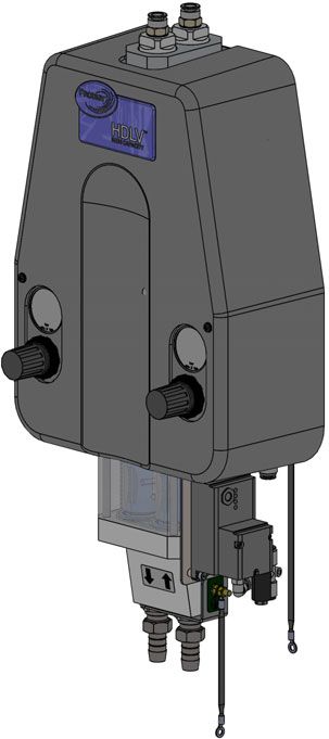
6 Prodigy Generation II High-Capacity HDLV Pump

Theory of Operation

Pumping
See Figure 3. The Prodigy high-capacity HDLV pump consists of two halves that function identically. The
halves alternately draw powder in and force powder out of the pump; while one half is drawing powder in, the
other half is forcing powder out.

             Front Half in Suction Phase                           Rear Half in Delivery Phase
 The front suction pinch valve is open, and the           The rear suction pinch valve is closed, and the
 front delivery pinch valve is closed. A vacuum is        rear delivery pinch valve is open. Air pressure is
 applied to the front fluidizing tube, which draws        applied to the rear fluidizing tube, forcing the
 powder through the suction tubing, inlet fitting,        powder out of the fluidizing tube and through the
 inlet lower Y-block, front suction pinch valve, and      rear delivery pinch valve, lower Y-block, delivery
 into the front fluidizing tube.                          fitting, and delivery tubing to the powder
 After a set period of time, the vacuum is shut off       destination.
 and the front suction pinch valve closes.
                                                        Next each halves switches to the alternate phase.
                                                        The front half now forces out the powder in the
                                                        fluidizing tubes while the rear half draws powder in.

                  Air                                               Air

                        Air         Air                                   Air              Air

                  Powder                                             Powder

Figure 3    Theory of Operation — Pumping

Part 1619979-01                                                                         E 2021 Nordson Corporation
Prodigy Generation II High-Capacity HDLV Pump 7
Purging Pulses of
Line Air Pressure
NOTE: The pump purge process is dependent on
how the pump is integrated into a powder coating
system.
See Figure 4. The pump must be operating while it
is purged. During the purge, line air pressure flows
through the fluidizing tubes, the pinch valves, and
out the suction and delivery lines.
If the purge air is supplied from a feed center or
bulk delivery system it is typically pulsed. The
pulses are typically 250 milliseconds on and 250
milliseconds off.
If the purge is manually initiated by pressing the
purge button on a manual pump station, the purge
air is not pulsed. The purge button should be
pressed repeatedly to supply air in pulses.
Figure 4 Theory of Operation — Purging
E 2021 Nordson Corporation Part 1619979-018 Prodigy Generation II High-Capacity HDLV Pump
Specifications
Output (Maximum) 4 kg (9 lb) per minute
Input Air (at pump inlet) 4.8−6.2 bar (70−90 psi)
Purge Air Line Air Pressure (7 bar (100 psi) maximum)
Operating Air Pressures
Pinch Valves 2.4−2.75 bar (35−40 psi)
Conveying Air 0.7−1.0 bar (10−15 psi)
Air Consumption
Conveying Air 28−56 l/min (1−2 cfm)
Total Consumption 255−311 l/min (9−11 cfm)
Electric Input (pump without generator) 24 Vdc, 1.75 W (73 mA)
Tubing Size
Air Input 10-mm OD polyurethane, 10-m (33-ft) long max
Powder Suction 19-mm OD antistatic hose, 3.65-m (12-ft) long max
Powder Delivery 19-mm OD antistatic hose, 30.5-m (100-ft) long
max
NOTE: For best results, keep the powder suction
and delivery tubing as short as possible.
Dimensions See Figure 5.
586 mm
(23.1 in.)
738 mm
(29.1 in.)
264 mm
160.9 mm (10.4 in.)
(6.336 in.)
Figure 5 Pump Dimensions
Part 1619979-01 E 2021 Nordson CorporationProdigy Generation II High-Capacity HDLV Pump 9
Approval Label
1620616
Figure 6 Approval Label
E 2021 Nordson Corporation Part 1619979-0110 Prodigy Generation II High-Capacity HDLV Pump
Installation
WARNING: The pump must be securely connected to a true earth ground. Failure to ground the
pump could result in a fire or explosion.
NOTE: The pump is normally mounted on a panel that includes an operating air regulator, and a manual
pushbutton and piloted-operated air valve for manual purging. The panel may also include an auxiliary
regulator for fluidizing the powder source.
160.0 mm
(6.299 in.) A A
5x
7.0 mm
(0.276 in.)
292 mm
(11.497 in.)
152.0 mm
(5.984 in.)
See Note C
Ship with
Expander
B C D
Delivery Suction
Maximum Maximum
30.5 m (100 ft) 3.65 m (12 ft)
200.0 mm
(7.874 in.)
Tubing Connections
Panel Mounting Dimensions NOTE B: For best results, keep the powder
Use the supplied M6 screws, washers, and nuts to mount the pump. suction and delivery tubing as short as possible.
NOTE A: Five mounting holes and four sets of M6 fasteners are included. NOTE C: Location of ship with expander and
Use the four mounting holes that best match your mounting surface. connection for 10 mm tubing for versions without
generator.
CONNECTION TYPE FUNCTION
A 10 mm blue polyurethane tubing From customer-supplied purge air source (7 bar [100 psi] max)
B 19 mm antistatic tubing Delivery: to powder destination
C 19 mm antistatic tubing Suction: from powder source
D 10 mm blue polyurethane tubing From input air source 4.8−6.2 bar (70−90 psi)
Pump ground wire To earth ground
Figure 7 Pump Installation
Part 1619979-01 E 2021 Nordson CorporationProdigy Generation II High-Capacity HDLV Pump 11
Operation
See Figure 8 and Table 1 for typical operating pressures. After making the initial pump assist and pinch air
pressure settings, adjustments should not be needed again.
The settings listed are approximate. Adjust as needed during setup to obtain desired results.
Pump with Generator
1. To start the pump, turn on the operating air supply.
2. Regulate the air pressure to typical operating pressure or 4.8−6.2 bar (70−90 psi).
3. To stop the pump, turn off the operating air supply.
Pump without Generator
CAUTION: 24 Vdc must be applied to the pump before (or at the same time) air supply is
applied. If pressure is applied without 24 Vdc, the pump will not operate properly and fill with
powder.
1. To start the pump, turn on 24 Vdc and the operating air supply.
2. Regulate the air pressure to typical operating pressure or 4.8−6.2 bar (70−90 psi).
3. To stop the pump, turn off the operating air supply and 24 Vdc.
Purge Air
Conveying Air
Pressure
Pinch Pressure
Pump Input Air
Tubing
(OD Size and
Length)
Pump Input Air Regulator
Possible Locations
-- Powder feed center for cyclone
Input Air reclaim or virgin bulk feed pump
(without generator) -- Cyclone for reclaim pump
-- Pump Station
Input Air
(with generator)
Supply Air from System
or Plant 7-bar (100 psi)
Powder Powder 255-311 l/min (9-11 cfm)
Delivery Suction
Figure 8 Pump Operation
E 2021 Nordson Corporation Part 1619979-0112 Prodigy Generation II High-Capacity HDLV Pump
Table 1 Typical Operating Air Pressures (Refer to Figure 8)
Air Pressure Settings
Pump with Generator Pump without Generator
(requires air to operate) (requires 24 Vdc and
air to operate)
Pump Input Air − Regulator/gauge connected 4.8 bar (70 psi) 4.8 bar (70 psi)
with tubing to pump input air, 10-mm tubing
(optional: 8-mm)
4-m (13-ft) long max
Pump Input Air − Regulator/gauge connected 5.5 bar (80 psi) 4.8 bar (70 psi)
with tubing to pump input air, 10-mm tubing
10-m (33-ft) long max
Purge Air 7 bar (100 psi) 7 bar (100 psi)
Pinch Valve Air (right regulator of the pump) 2.4 bar (35 psi) 2.4 bar (35 psi)
Conveyance Air (left regulator on pump) 1.0 bar (15 psi) 1.0 bar (15 psi)
Part 1619979-01 E 2021 Nordson CorporationProdigy Generation II High-Capacity HDLV Pump 13
Maintenance
Perform these maintenance procedures to keep your pump operating at peak efficiency.
WARNING: Allow only qualified personnel to perform the following tasks. Follow the safety
instructions in this document and all other related documentation.
NOTE: You may have to perform these procedures more or less frequently, depending on factors such as
operator experience and type of powder used.
Frequency Part Procedure
Inspect the pinch valve body for signs
of powder leakage. If you see powder
in the pinch valve body or stress cracks
in the pinch valves, replace the pinch
valves.
Daily
Pinch Valves
Kit 1092273
Disassemble the pump assembly and
inspect the lower Y-block and upper
Y-manifold for signs of wear or impact
fusion. Clean these parts in an
ultrasonic cleaner if necessary.
NOTE: To reduce downtime, keep a
spare upper Y-manifold and lower
Every Six Months Upper Y-Manifold Y-block in stock to install while you are
Kit 1057269 cleaning the other set.
or
Each Time You
Disassemble the
Pump
Lower Y-Block
with barbed fitting
Part 1610762
E 2021 Nordson Corporation Part 1619979-0114 Prodigy Generation II High-Capacity HDLV Pump
Troubleshooting
Problem Possible Cause Corrective Action
1. Reduced powder Blockage in the powder tubing to Check the tubing for blockages.
output the destination Purge the pump.
(pinch valves are
opening and closing) Conveying air is set too high Decrease the conveying air pressure.
Conveying air is set too low Increase the conveying air pressure.
Defective pinch valve Replace the pinch valves.
Fluidizing tubes clogged Replace the fluidizing tubes.
Conveying air solenoid valve not Refer to the Tubing Diagrams on
actuating pages 28 and and 29.
1. Turn off the pump and disconnect
tubes J and K from the top of the
pump.
2. Turn the pump on and check the
tubes for alternating positive and
negative air pressure.
S If there is no pressure, replace
the valve.
S If the valve is actuating, but
you cannot feel positive or
negative air pressure at the
tubes, check for obstructions in
the air lines leading in and out
of the valve.
Timing Control Valve not actuating Refer to Prodigy Electric Control
OR HDLV Kit on page 16 for
troubleshooting related to items
Fault in Prodigy electric control included in kit.
HDLV kit
2. Reduced powder Defective pinch valve Replace the pinch valves.
output Defective check valve Replace the check valves.
(pinch valves are not
opening and closing) Pinch pressure solenoid valve not Refer to the Tubing Diagrams on
actuating pages 28 and and 29. Turn off the
pump and disconnect tubes H and G
from the pump. Turn the pump on
and check the tubes for alternating
positive air pressure. If there is no
pressure, replace the valve.
If the valve is actuating, but you
cannot feel air pressure at the tubes,
check for obstructions in the air lines
leading in and out of the valve.
Timing Control Valve not actuating Refer to Prodigy Electric Control
OR HDLV Kit on page 16 for
troubleshooting related to items
Fault in Prodigy electric control included in kit.
HDLV kit
Continued...
Part 1619979-01 E 2021 Nordson CorporationProdigy Generation II High-Capacity HDLV Pump 15
Problem Possible Cause Corrective Action
3. Reduced powder Blockage in the powder tubing Check the tubing for blockages.
input (loss of suction from the feed source Purge the pump.
from powder source) Loss of vacuum at the vacuum Check the vacuum generator for
generator contamination.
Check the exhaust muffler. If the
exhaust muffler appears to be
plugged, replace it.
Damaged O-rings in powder path Check all powder path O-rings.
Replace any worn or damaged
O-rings.
4. Pinch valves failing Pump is not properly grounded. Check that pump and hoses are
rapidly, cracking Powder is tribo-charging in the properly grounded. Replace pinch
around the flange pump and grounding through the valves. Refer to Parts for
pinch valves. replacement.
E 2021 Nordson Corporation Part 1619979-0116 Prodigy Generation II High-Capacity HDLV Pump
Prodigy Electric Control Timing Valve Kit
See Figure 9 and refer to Tables 2 and 3 for NOTE: Generator LED not applicable on
troubleshooting related to items included in the assemblies without generator.
Prodigy electric timing valve kit. NOTE: Timing Control Valve Connector referred to
as Connector in tables 2 and 3.
Timing Control Valve
Connector LED
Generator LEDs
10019903
Figure 9 Location of Diagnostic LEDs
Table 2 Normal Operating State for LEDs
Generator Timing Control Valve
LED States Connector LED State
Green Red Red
Flashing OFF Flashing
NOTE: This assumes proper operating air pressure settings are
applied to pump (refer to Operation section on page 11 for settings).
Part 1619979-01 E 2021 Nordson CorporationProdigy Generation II High-Capacity HDLV Pump 17
Table 3 Troubleshooting LED States for Prodigy Electric Control Timing Valve Kit
Generator LED Connector Possible Cause Corrective Action
States LED State
Green Red Red
NOTE: If LEDs are not in their normal Air supply to pump is 1. Increase air pressure to transfer
operating state, it is recommended to first too low pump assembly 4.8−6.2 bar
go through corrective action steps for “Air (70−90 psi) until the timing valve
supply to pump is too low” before using and pump operates.
LED states to diagnose other possible
causes. 2. Check if LEDs indicate their
normal operating state. If not,
continue to next step.
3. Check air supply tubing to pump
for OD size and approximate
length. If tubing OD is 8 mm and
tubing length is greater than 4 m
long, replace with 10-mm tubing.
Use an expander at the pump
input air location and also at the
air source to adapt 10 mm tubing
to existing 8 mm connection, if
needed.
4. Adjust air supply pressure to
transfer pump to 5.5 bar (80 psi)
or higher until timing valve and
pump operate.
OFF OFF OFF Fault with generator 1. Increase air pressure to transfer
pump assembly 4.8−6.2 bar
(70−90 psi) until the timing valve
and pump operates.
2. Check if LEDs indicate their
normal operating state. If not,
continue to next steps.
3. If the green generator LED is not
Flashing Flashing OFF flashing, replace the generator
kit (refer to Spare Parts section
on page 42 for part number).
4. If green generator LED is
flashing, but the red connector
LED is OFF, refer corrective
action steps for “Fault in Prodigy
electric control HDLV kit.”
Continued...
E 2021 Nordson Corporation Part 1619979-0118 Prodigy Generation II High-Capacity HDLV Pump
Generator LED Connector Possible Cause Corrective Action
States LED State
Green Red Red
Flashing OFF OFF Fault in Prodigy electric For versions with generator, go
control HDLV kit to step 4.
For versions without generator
complete the following steps:
1. Check that 24 Vdc is being
supplied to the pump.
2. Check that air supply pressure to
transfer pump is set properly.
3. Check that the 24 Vdc and air
supply turn ON and OFF at the
same time. If both are working
and timing control valve LED is
still not flashing, continue to step
4.
4. Increase air pressure to transfer
pump assembly 4.8−6.2 bar
(70−90 psi) until the timing valve
and pump operates.
5. Check if LEDs have returned to
their normal operating state. If
not, continue to next step.
6. Replace Prodigy electric control
HDLV kit (refer to Spare Parts
section on page 42 for part
numbers).
Continued...
Part 1619979-01 E 2021 Nordson CorporationProdigy Generation II High-Capacity HDLV Pump 19
Generator LED Connector Possible Cause Corrective Action
States LED State
Green Red Red
Flashing OFF Flashing Timing control valve not 1. Increase air pressure to transfer
actuating pump assembly 4.8−6.2 bar
(70−90 psi) until the timing valve
NOTE: LEDs will show
and pump operates.
in normal operating state
when dealing with this 2. Check to see if timing valve and
particular cause. pump are operating consistently
at 1 second per cycle rate.
3. If not, turn off pump.
4. Refer to Tubing Diagrams on
pages 28 and 29. Disconnect
tubes L and M from the timing
control valve.
5. Turn pump on and check the
timing control valve for
alternating positive air pressure
0.5 seconds ON and 0.5
seconds OFF.
6. If air is not alternating at
consistent rate, replace the
timing control valve kit (refer to
Spare Parts section on page 42
for part number).
E 2021 Nordson Corporation Part 1619979-0120 Prodigy Generation II High-Capacity HDLV Pump
Repair
WARNING: Allow only qualified personnel to perform the following tasks. Follow the safety
instructions in this document and all other related documentation.
WARNING: Shut off and relieve system air pressure before performing the following tasks.
Failure to relieve air pressure may result in personal injury.
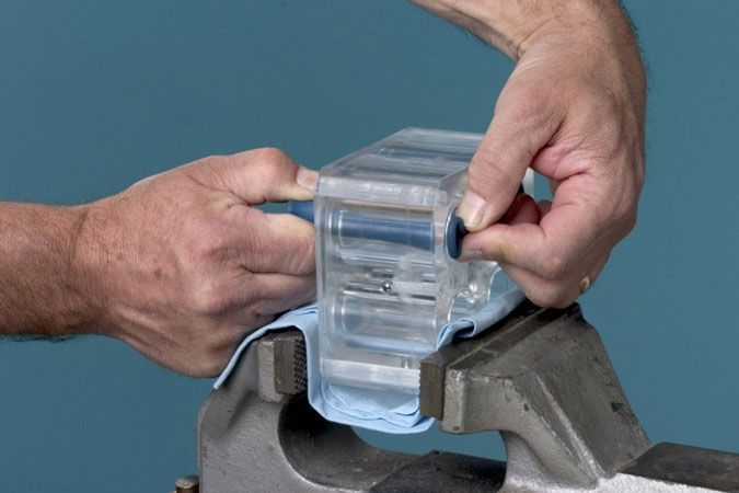
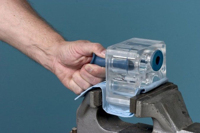
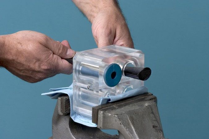
Fluidizing Tube Replacement
NOTE: Four O-rings are included in the fluidizing tube kit. Replace the O-rings if they are worn. It is not
necessary to replace the O-rings each time you replace the fluidizing tubes.
1 2
Remove the fluidizing
Shut off and relieve purge tube access plugs
air pressure. Pull the fluidizing tubes
Disconnect the purge air straight out of the pump.
tubing.
3 4 Tighten the fluidizing
tube access plugs to
Check the O-rings in the inside height range.
diameter of the access plugs. Insert the Connect the purge
Replace them if necessary. fluidizing tubes air tubing.
straight into the
Look down into the pump to make sure the O-rings pump.
are seated in the upper-Y manifold. If they are not
Top of Plug
seated, use the fluidizing tubes to seat them.
Height Range
5/16−3/8 in.
(7.9−9.5 mm)
Top of
Fluid Tube
Housing
Assembly
Part 1619979-01 E 2021 Nordson CorporationProdigy Generation II High-Capacity HDLV Pump 21
Pump Disassembly
WARNING: Shut off and relieve system
air pressure before performing the K J
following tasks. Failure to relieve air
pressure may result in personal injury.
NOTE: Tag all air and powder tubing before
disconnecting from the pump.
1. See Figure 10. Disconnect the purge air lines
from the top of the pump.
2. Disconnect the inlet and outlet powder tubing
from the bottom of the pump. A
3. Remove the two screws (A) and the cover from
the pump. B
4. See Figure 11. Disconnect one end of each of
the seven air tubes indicated.
NOTE: The letters in Figure 11 correspond to
the letters in the Tubing Diagram on page 28.
5. See Figure 10. Remove the two screws (B)
securing the pump assembly to the base.
H G
Remove the pump assembly to a clean work
surface.
6. See Figure 12. Starting with the fluidizing U
tubes, disassemble the pump as shown.
NOTE: Refer to Pinch Valve Replacement on
page 26 for pinch valve replacement instructions.
Filter discs are included in pinch valve kits.
A
A
B Figure 11 Disconnecting Air Tubing
Figure 10 Removing the Pump Assembly
E 2021 Nordson Corporation Part 1619979-0122 Prodigy Generation II High-Capacity HDLV Pump
1
6
7
2
16
19
17
3
18 9
8
17
10
4
15
5
11
12
4
13
14
Figure 12 Pump Disassembly and Assembly
1. 10-mm tube connectors (2) 7. Filter discs (2) 14. 19 mm barbed fittings (2)
2. Check valves (2) 8. Fluidizing tubes (2) 15. O-rings (2), 0.219 x 0.406 in.
3. Fluidizing tube access plugs (2) 9. Upper-Y manifold 16. O-rings (2), 1.188 x 1.375 in.
4. 6-mm tube connectors (4) 10. Pinch valves (4) 17. O-rings (4), 0.688 x 0.875 in.
5. Outer fluidizing tube assembly 11. Pinch valve body 18. O-rings (2), 1.25 x 1.063 in.
6. O-rings (2), 0.625 x 0.813 in. 12. Lower Y-block 19. O-rings (2), 0.438 x 0.625 in.
13. 120-mm screws (4)
Part 1619979-01 E 2021 Nordson CorporationProdigy Generation II High-Capacity HDLV Pump 23
Pump Assembly
CAUTION: Follow the assembly order and specifications shown. Pump damage may occur if you
do not carefully follow the assembly instructions.
1 Refer to Pinch Valve 4
Replacement on
page 26 for specific
instructions.
5
11
9
10
11
12
2
15
1 4 13
11
3 2
Tighten screws two
turns at a time to
7−10 in. lb using an
3
6 alternating pattern.
17
7
16
9
E 2021 Nordson Corporation Part 1619979-0124 Prodigy Generation II High-Capacity HDLV Pump
5 8
1 K J
2
20
3
A
B
19
18
6
H G
Tighten securely to
height range.
U
Top of Plug
Height Range
5/16−3/8 in.
(7.9−9.5 mm)
Top of
Fluid Tube
Housing
Assembly
7
Part 1619979-01 E 2021 Nordson CorporationProdigy Generation II High-Capacity HDLV Pump 25 9 E 2021 Nordson Corporation Part 1619979-01
26 Prodigy Generation II High-Capacity HDLV Pump

Pinch Valve Replacement
            CAUTION: Before placing the pinch valve body in a vise, pad the jaws. Tighten the vise only
            enough to hold the valve body firmly. Failure to observe may result in damage to the pinch valve
            body.

NOTE: The top flanges of the pinch valves have the word UP molded into them.

NOTE: Replace the filter discs (included in the pinch valve kit) when you replace the pinch valves. Refer to
step 7 of the Pump Assembly procedure.
Pinch Valve Removal

 1

 Place the pinch valve body in a padded vise with
 the bottom end facing you. Grasp and pull the
 bottom end of the pinch valve with one hand.

 2

 Use your other hand to pinch the flange on the
 opposite end of the pinch valve.

 3

 Pull the pinch valve firmly until it comes out of
 the pinch valve body.

Part 1619979-01                                                                          E 2021 Nordson Corporation
Prodigy Generation II High-Capacity HDLV Pump 27
Pinch Valve Installation
3
NOTE: All pinch valves intended for repeated
contact with food must be thoroughly cleansed prior
to their first use.
1
While keeping the UP end flange pinched flat,
pull on the the insertion tool.
4
Turn the pinch valve body around so that the top
end faces you. Insert the pinch valve insertion
tool through the pinch valve body.
Pull the insertion tool through the valve body
until the UP end of the pinch valve and the
insertion tool comes out the top of the pinch
valve body.
NOTE: After you put the pinch valve into the
insertion tool, pinch flat the flange on the UP end
of the valve.
2
Insert the UP end of the pinch valve into the
pinch valve insertion tool. Pinch the UP end
flange flat and feed the small end of the
flattened flange into the pinch valve body.
E 2021 Nordson Corporation Part 1619979-0128 Prodigy Generation II High-Capacity HDLV Pump
Tubing Diagrams
See Figures 13 and 14 and refer to table on page 30 for tube routings for pump assembly.
NOTE: Refer to page 10 for proper installation location of ship with expander for each version of the pump.
S
T
L
N K
M
A N R
K R
L J
J
C
E
P T D
P B
O
B
Q M
F
H
Q A
U
F H E
G S
G
O
C
V
V
U
D
W
W
Ship with Expander
10019903
Figure 13 Tubing Diagram — 1 of 2
Part 1619979-01 E 2021 Nordson CorporationProdigy Generation II High-Capacity HDLV Pump 29
M
A L
N
K T M
R
F J
L S
J N
P B
T B
D
H
P M G
E
F A
H
Q O S
U
V
G
O W
C U Ship
with
Expander
F
D E
10019903
Figure 14 Tubing Diagram — 2 of 2
E 2021 Nordson Corporation Part 1619979-0130 Prodigy Generation II High-Capacity HDLV Pump
Refer to Parts for tubing part numbers.
Length Length
OD Color OD Color
mm (in.) mm (in.)
A — A 6 mm Blue 213 (8.37) M — M 4 mm Clear 243 (9.56)
B — B 6 mm Blue 213 (8.37) N — N 4 mm Clear 123 (4.83)
C — C 6 mm Blue 273 (10.74) O — O 4 mm Clear 123 (4.83)
D — D 6 mm Blue 238 (9.36) P — P 4 mm Clear 108 (4.25)
E — E 6 mm Blue 383 (15.07) Q — Q 4 mm Clear 108 (4.25)
F — F 6 mm Blue 383 (15.07) R — R 6 mm Blue 260 (10.25)
G — G 6 mm Blue 278 (10.93) S — S 8 mm Blue 433 (17.04)
H — H 6 mm Blue 213 (8.37) T — T 8 mm Blue 238 (9.36)
J — J 6 mm Blue 153 (6.01) U — U 10 mm Blue 223 (8.77)
K — K 6 mm Blue 118 (4.63) V — V 8 mm Blue 98 (3.88)
L — L 4 mm Clear 300 (11.81) W —W 6 mm Blue 50 (2.00)
Part 1619979-01 E 2021 Nordson CorporationProdigy Generation II High-Capacity HDLV Pump 31
Parts
To order parts, call the Nordson Finishing Customer Support Center at (800) 433-9319 or your local Nordson
representative. Use the parts illustrations and parts lists to locate and describe parts correctly.
Using the Illustrated Parts List
Numbers in the Item column correspond to numbers that identify parts in illustrations following each parts
list. The code NS (not shown) indicates that a listed part is not illustrated. A dash (—) is used when the part
number applies to all parts in the illustration.
The number in the Part column is the Nordson Corporation part number. A series of dashes in this column
(- - - - - -) means the part cannot be ordered separately.
The Description column gives the part name, as well as its dimensions and other characteristics when
appropriate. Indentions show the relationships between assemblies, subassemblies, and parts.
S If you order the assembly, items 1 and 2 will be included.
S If you order item 1, item 2 will be included.
S If you order item 2, you will receive item 2 only.
The number in the Quantity column is the quantity required per unit, assembly, or subassembly. The code
AR (As Required) is used if the part number is a bulk item ordered in quantities or if the quantity per
assembly depends on the product version or model.
Letters in the Note column refer to notes at the end of each parts list. Notes contain important information
about usage and ordering. Special attention should be given to notes.
Item Part Description Quantity Note
— 0000000 Assembly 1
1 000000 S Subassembly 2 A
2 000000 S S Part 1
E 2021 Nordson Corporation Part 1619979-0132 Prodigy Generation II High-Capacity HDLV Pump
Pump Assembly
1
4
5
3
2
Figure 15 Cover and Mounting Parts
Part 1619979-01 E 2021 Nordson CorporationProdigy Generation II High-Capacity HDLV Pump 33
See Figure 15.
Item Part Description Quantity Note
— 1619673
PUMP, high capacity, HDLV, electric, barbed, 1
Prodigy, with generator, packaged
— 1619912 PUMP, high capacity HDLV, electric, barbed, 1
Prodigy, no generator, packaged
1 ------ S PUMP CONTROLS 1 A
2 ------ S PUMP ASSEMBLY 1 B
3 345537 S SCREW, socket, M5 x 90, black 2
4 1054586 S COVER, high capacity HDLV pump 1
5 982825 S SCREW, pan head, recessed, M4 x 12, 2
with integral lockwasher bezel
NS 981830 S SCREW, socket, M6 x 25, zinc 4 C
NS 984703 S NUT, hex, M6, steel, zinc 4 C
NS 983029 S WASHER, flat, M, regular, M6, steel, zinc 8 C
NS 983409 S WASHER, lock, M, split, M6, steel, zinc 4 C
NOTE A: Refer to Pump Controls on page 36 for a breakdown of the parts included in this assembly.
B: Refer to Pump Assembly without Controls on page 34 for a breakdown of the parts included in this
assembly.
C: Use these fasteners to mount the pump.
NS: Not Shown
E 2021 Nordson Corporation Part 1619979-0134 Prodigy Generation II High-Capacity HDLV Pump
Pump Assembly without Controls
1 6
2 7
16
19
3 17
18
9
8
17
10
4
15
5
11
12
4
13
14
Figure 16 Pump Assembly Without Controls
Part 1619979-01 E 2021 Nordson CorporationProdigy Generation II High-Capacity HDLV Pump 35
See Figure 16.
Item Part Description Quantity Note
− ------ PUMP ASSEMBLY 1
1 971102 S CONNECTOR, male, 10 mm tube x 3/8 2
unithread
2 ------ S CHECK VALVE assembly, pump, Prodigy 2 C
3 ------ S PLUG, fluidizing tube, high capacity HDLV 2
pump
4 972141 S CONNECTOR, male, 6 mm tube x 1/8 universal 4
5 ------ S TUBE, outer fluid assembly, high capacity 1
HDLV pump
6 941143 S O-RING, silicone, 0.625 x 0.813 x 0.094 in. 2
7 ------ S DISC, filter, Prodigy HDLV pump 2 A
8 ------ S TUBE, fluidizing, high capacity HDLV pump 2 B
9 1057269 S KIT, upper Y manifold, high capacity HDLV 1
pump
10 ------ S VALVE, pinch, high capacity HDLV pump 4 A
11 1090737 S BODY, pinch valve, high capacity HDLV pump 1
12 1610762 S KIT, lower Y-block, with barbed fittings, high 1
capacity HDLV pump
13 1054518 S SCREW, socket, M6 x 120, stainless steel 4
14 ------ S FITTING, barbed, G ½ male, 12.7 mm hose, 2
stainless steel
15 1053292 S O-RING, silicone, 0.219 x 0.406 x 0.094 in. 2
16 941231 S O-RING, silicone, 1.188 x 1.375 x 0.094 in. 2
17 941153 S O-RING, silicone, 0.688 x 0.875 x 0.094 in. 4 B
18 941215 S O-RING, silicone, 1.250 x 1.063 x 0.094 in. 2
19 941113 S O-RING, silicone, 0.438 x 0.625 x 0.094 in. 2
NOTE A: These parts are included in the Pinch Valve Service Kit 1092273.
B: These parts are included in the Fluidizing Tube Service Kit 1104542.
C: To replace both check valves, order the Check Valve Service Kit 1078161.
E 2021 Nordson Corporation Part 1619979-0136 Prodigy Generation II High-Capacity HDLV Pump
Pump Controls
Left Side
2 1
3 3
4
5
2
6
3
7 2
3
4
5 7
6
2
11 8
10
9
Figure 17 Pump Controls — Left Side (shown with generator version )
Part 1619979-01 E 2021 Nordson CorporationProdigy Generation II High-Capacity HDLV Pump 37
See Figure 17.
Item Part Description Quantity Note
1 1056480 UNION, tee, 4 mm tube x 4 mm tube x 4 mm tube 2
2 1054534 CONNECTOR, male, universal elbow, 4 mm tube x 4
M5
3 972126 CONNECTOR, male, universal elbow, 6 mm tube x 8
1/ in.
8
4 982650 SCREW, socket, M3 x 20 long, black 4
5 983400 WASHER, lock, M, split, steel, zinc 4
6 1054519 VALVE, miniature, double air piloted, 5 port 2
7 170269 MUFFLER, exhaust, 1/8 in. NPT 2
8 1018157 REGULATOR ASSEMBLY, 0−25 psi, 0−1.7 bar 1
9 1097195 MUFFLER, silencer, 1/4 NPT 1
10 1005068 UNION, female bulkhead, 10 mm tube x 1/4 RPT 1
11 1052893 ELBOW, plug in, 10 mm tube x 10 mm stem 2
E 2021 Nordson Corporation Part 1619979-0138 Prodigy Generation II High-Capacity HDLV Pump
Right Side
25
20
24 13
16 21
26
17
18
13 19
16
35
15
14 27
28
12
13 22
29
30 11
31 34
33
32
23 21
19
36
Figure 18 Pump Controls — Right Side (shown with generator version)
Part 1619979-01 E 2021 Nordson CorporationProdigy Generation II High-Capacity HDLV Pump 39
See Figure 18.
Item Part Description Quantity Note
12 982517 SCREW, socket, M4 x 20, zinc 2
13 983403 WASHER, lock, M, split, M4, steel, zinc 8
14 1052920 PUMP, vacuum generator 1
15 1019093 CONNECTOR, plug in Y, 8 mm stem x 6 mm tube 1
16 984715 NUT, hex, M4, steel, zinc 6
17 1056465 ELBOW, plug in, 8 mm tube x 8 mm stem, plastic 1
18 1054619 UNION, cross, 4 mm tube x 8 mm tube 1
19 972286 REDUCER, 8 mm stem x 6 mm T AR
20 1620576 KIT, valve, 5 port, 2 position, NPTF 1 C
21 972126 CONNECTOR, male, elbow, 6 mm T x ⅛ UNI AR A, C
22 1620577 KIT, generator, 12 Vdc, Prodigy 1 B, C
23 972313 S TEE, union, 8 mm tube x 8 mm tube, plastic 1 B
24 ------ HOLDER, clamping, spring action 1
25 1063245 SPRING, tapered, 0.312 x 0.750 in., pump 1
grounding
26 983402 WASHER, flat, M, narrow, M4, steel, zinc 4
27 1054617 NIPPLE, reducing, 10 mm tube x 8 mm tube, 1
plastic
28 1054616 UNION, tee, 8 mm tube x 6 mm tube x 6 mm tube 1
29 984706 NUT, hex, M5, steel, zinc 1
30 983401 WASHER, lock, M, split, M5, steel, zinc 1
31 983021 WASHER, flat, E, 0.203 x 0.406 x 0.040 in., brass 1
32 1615891 JUMPER, ground, 9 in. 1
33 240674 TAG, ground 1
34 1002711 UNION, bulkhead, 8 mm tube x 8 mm tube 1
35 288821 REGULATOR ASSEMBLY, 0−60 psi, 0−4 bar 1
36 1618985 EXPANDER, 8 mm stem x 10 mm T 1 D
NOTE A: Included in valve kit (1620576) and generator kit (1620577).
B: Not included in pump without generator (1619912).
C: Included in Prodigy electric control HDLV kit. Refer to Spare Parts section for kit part numbers.
D: Ship with item. See Installation section on page 10 for proper installation for each version of the pump.
AR: As Required
E 2021 Nordson Corporation Part 1619979-0140 Prodigy Generation II High-Capacity HDLV Pump
Powder and Air Tubing
NOTE: Refer to page 10 for proper installation location of ship with expander for each version of the pump.
D D
B B
B
A A C
C
A
A
A A
A
B
B A
A A
B C A
A
B B B A
A
B C
C
A
A
A
C
Without
Generator
B A A
D With
Generator
E E
A A
A A
10019903
Figure 19 Powder and Air Tubing
Tubing Part Description Notes
A 900742 6-mm OD, blue
B 900617 4-mm OD, clear
C 900618 8-mm OD, blue
D 900740 10-mm OD, blue
E 768178 12.7-mm ID, antistatic
Part 1619979-01 E 2021 Nordson CorporationProdigy Generation II High-Capacity HDLV Pump 41
Spare Parts
Keep one of each of these assemblies in stock for each pump in your system.
Pinch Valve Check Valve Service
Kit 1097919 Kit 1078161
(Includes (Quantity of 2)
4 pinch valves,
2 filter discs,
2 O-rings,
and 1 insertion tool)
Instructions on page 26 Check Valve Upgrade
Kit 1080160
Non-conductive Pinch Valve (Includes
Kit 1092273 2 connectors,
(Includes 2 check valves,
4 pinch valves, 2 plugs,
2 filter discs, 6 O-rings)
2 O-rings,
and 1 insertion tool) Use to upgrade older
Instructions on page 26
pumps to new style
check valves
Standard Fluidizing Tube Kit
1104542
(Includes 2 fluidizing tubes
and 4 O-rings)
Instructions on page 20 Miniature Valve
Part 1054519
(Quantity of 1)
Upper Y Manifold
Kit 1057269 Generation II Pinch
(Includes Valve Upgrade Kit
1 manifold Part 1092271
and 2 O-rings) (Converts
Instructions on page 21 1081246 to 1092240
1087221 to 1092242)
Lower Y-Block with
grounded tubing
barbed fittings
Part 1610762
(Quantity of 1)
Instructions on page 21
E 2021 Nordson Corporation Part 1619979-0142 Prodigy Generation II High-Capacity HDLV Pump
Spare Parts (contd)
Timing Control Valve
Part 1620576
(Quantity of 1)
Prodigy Electric
Control HDLV Kit
With Generator
1619498 Generator Kit
Without Generator Part 1620577
1619748 (Quantity of 1)
Note: Image shown
with generator version.
Part 1619979-01 E 2021 Nordson CorporationEU DECLARATION of CONFORMITY
Product: Prodigy HDLV High Capacity Transfer Pump
This Declaration is issued under the sole responsibility of the manufacture.
Models: Prodigy HD
Description: This is a high-density powder pump used for high capacity transfer of powder coating
materials.
Applicable Directives:
2006/42/EC – Machinery Directive
2014/34/EU – ATEX Directive
Standards Used for Compliance:
EN/ISO12100 EN IEC 60079-0
EN60204 EN 60079-31
Markings & File Info:
Ex II 3D
Ex tc IIIC T85°C Dc
Tech File – Sira CSA Group, Netherlands NB 2813
Quality System:
- ISO9001
- SGS Fimko Oy, NB 0598 (Helsinki Finland)
___________________ Date: 08DEC20
Jeremy Krone
Supervisor Product Development Engineering
Industrial Coating Systems
Amherst, Ohio, USA
Nordson Authorized Representative in the EU
Contact: Operations Manager
Industrial Coating Systems
Nordson Deutschland GmbH
Heinrich-Hertz-Straße 42-44
D-40699 Erkrath
Nordson Corporation Westlake, Ohio
DOC14050-01You can also read