Alignment and assembly process for primary mirror subsystem of a spaceborne telescope
←
→
Page content transcription
If your browser does not render page correctly, please read the page content below
Alignment and assembly process for
                 primary mirror subsystem of a
                 spaceborne telescope

                 Wei-Cheng Lin
                 Shenq-Tsong Chang
                 Sheng-Hsiung Chang
                 Chen-Peng Chang
                 Yu-Chuan Lin
                 Chi-Chieh Chin
                 Hsu-Pin Pan
                 Ting-Ming Huang

Downloaded From: https://www.spiedigitallibrary.org/journals/Optical-Engineering on 21 Jan 2021
Terms of Use: https://www.spiedigitallibrary.org/terms-of-use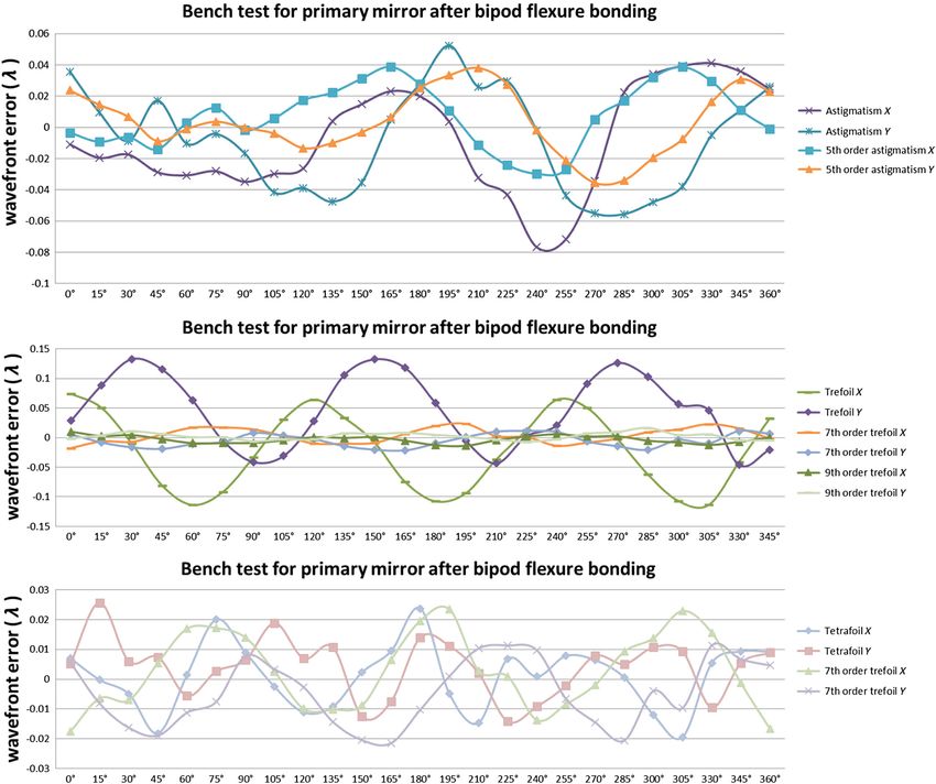
Optical Engineering 54(11), 115109 (November 2015)

                Alignment and assembly process for primary mirror
                subsystem of a spaceborne telescope
                Wei-Cheng Lin,a Shenq-Tsong Chang,a,* Sheng-Hsiung Chang,b Chen-Peng Chang,b Yu-Chuan Lin,a Chi-Chieh Chin,b
                Hsu-Pin Pan,a and Ting-Ming Huanga
                a
                 Instrument Technology Research Center, National Applied Research Laboratories, 20 R&D Road VI, Hsinchu Science-Based Industrial Park,
                Hsinchu 300, Taiwan
                b
                 National Space Organization, National Applied Research Laboratories, 8F, 9 Prosperity 1st Road, Hsinchu Science-Based Industrial Park,
                Hsinchu 300, Taiwan

                              Abstract. In this study, a multispectral spaceborne Cassegrain telescope was developed. The telescope was
                              equipped with a primary mirror with a 450-mm clear aperture composed of Zerodur and lightweighted at a ratio of
                              approximately 50% to meet both thermal and mass requirements. Reducing the astigmatism was critical for this
                              mirror. The astigmatism is caused by gravity effects, the bonding process, and deformation from mounting the
                              main structure of the telescope (main plate). This article presents the primary mirror alignment, mechanical
                              ground-supported equipment (MGSE), assembly process, and optical performance test used to assemble
                              the primary mirror. A mechanical compensated shim is used as the interface between the bipod flexure and
                              main plate. The shim was used to compensate for manufacturer errors found in components and differences
                              between local coplanarity errors to prevent stress while the bipod flexure was screwed to the main plate. After
                              primary mirror assembly, an optical performance test method called a bench test with an algorithm was used to
                              analyze the astigmatism caused by the gravity effect and deformation from the mounting or supporter. The tol-
                              erance conditions for the primary mirror assembly require the astigmatism caused by gravity and mounting force
                              deformation to be less than P − V 0.02 λ at 632.8 nm. The results demonstrated that the designed MGSE used in
                              the alignment and assembly processes met the critical requirements for the primary mirror assembly of the tele-
                              scope. © The Authors. Published by SPIE under a Creative Commons Attribution 3.0 Unported License. Distribution or reproduction of this work in
                              whole or in part requires full attribution of the original publication, including its DOI. [DOI: 10.1117/1.OE.54.11.115109]

                              Keywords: Cassegrain telescope; primary mirror; bipod flexure; shim; coordinate measuring machine; astigmatism.
                              Paper 151271P received Sep. 20, 2015; accepted for publication Oct. 23, 2015; published online Nov. 18, 2015.

                1 Introduction                                                                        aspheric figure for primary, secondary, and tertiary mirrors
                A coordinate measuring machine (CMM) is a rapid, flexible,                            during generation and rough polishing. Moreover, CMMs
                and capable tool, which can measure the dimensions, forms,                            are also used to assist the alignment of the primary mirror
                and positions of geometric objects. It can also be used in                            segment assembly to determine its contribution to the shim
                optical assembly processes to compare the assembly result                             prescription in the James Webb Space Telescope.3,4 A high-
                with the design tolerance. A typical CMM is composed of                               precision CMM is a suitable tool for aiding the alignment of
                three orthogonal linear moving axes with a probe attached                             multiple elements in mid-size to large optical assemblies.
                to the third moving axis, allowing a spherical stylus tip to                              This study presents advanced techniques used for primary
                conduct contact measurements on an object. Thus, the rela-                            mirror assembly and the analysis of the bipod flexure bond-
                tive positions of the features that are in the reference frame of                     ing position. Lin et al. described the procedures for aligning
                the machine and the reference frame based on the previously                           primary mirrors and adjusting the isostatic mount to optimize
                measured features of the object can also be calculated.1                              the bonding position of Cassegrain telescopes by using a
                Certain tolerances of optomechanical subassemblies, such                              CMM. The method is a precise and useful method for align-
                as the curvature radius, thickness, air space, decenter,                              ing mid-size to large optomechanical systems.5,6 Kihm et al.
                axial translation, tilt, and roll,2 can be derived by a precision                     proposed a novel design for adjustable bipod flexures used to
                CMM. Nevertheless, the surface accuracy of most critical                              mount mirrors and conduct optical experiments on a space
                optical components may be specified as λ∕20 at 632.8 nm.                              telescope. The design reduced the error caused by the gravity
                Only interferometers or high-accuracy stylus profile meters                           effect to less than root mean square 10 nm.7 Lin et al. pre-
                are sufficiently accurate to meet the λ∕20 measurement                                sented an optomechanical design and analysis method for a
                requirement.1 However, a CMM is still useful for assessing                            mirror mount integrated with a Cassegrain telescope. The
                the overall lens shape during manufacturing and at the accep-                         deformation of the primary mirror caused by the gravity
                tance phase, especially for large optical components. A Leitz                         load from various mirror mounting positions can be pre-
                CMM was used to develop the James Webb Space Telescope                                dicted using finite element analysis (FEA) before primary
                to control the radius of curvature, conic constant, and                               mirror assembly.8 Moreover, lightweight spaceborne mirrors
                                                                                                      have large gravity sags and are difficult to operate, mount,
                                                                                                      and fix;9 thus, testing techniques could be challenges espe-
                                                                                                      cially to verify the optical performance after a lightweight
                *Address all correspondence to: Shenq-Tsong Chang, E-mail: stc@itrc.narl.org
                 .tw                                                                                  mirror is mounted. In developing the Kepler photometer, a

                Optical Engineering                                                          115109-1                                              November 2015   •   Vol. 54(11)

Downloaded From: https://www.spiedigitallibrary.org/journals/Optical-Engineering on 21 Jan 2021
Terms of Use: https://www.spiedigitallibrary.org/terms-of-use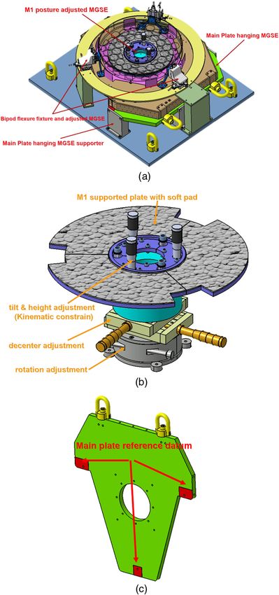
Lin et al.: Alignment and assembly process for primary mirror subsystem of a spaceborne telescope

                counterweighted zero-g mount during the assembly process
                and a vertical setup were used for averaging up-and-down
                test results to predict zero-g effects. In the vertical setup,
                a mirror is used to minimize gravity effects by combining
                analytical FEA modeling of the gravity sag with interfero-
                metric test data to approximate a gravity-free surface fig-
                ure.10 To specify the measured wavefront error contributed
                by manufacturing, gravity, and mounting force, Lin et al.
                proposed a novel method by using the characteristics of
                each Zernike term to obtain the absolute surface figure.11
                   This article presents the alignment and assembly proc-
                esses conducted using a high-performance CMM for a pri-
                mary mirror. A mechanical shim was used to compensate for
                manufacturer errors present in components. Differences
                between local coplanarity errors and the bipod flexure bond-
                ing position during alignment were also measured. The
                thickness of the mechanical shim was determined using a
                CMM. The bipod flexures were bonded to the mirror by
                injecting epoxy after the flexures were bolted on the main
                plate to minimize the deformation of the surface shape.
                After primary mirror assembly, an algorithm based on
                Zernike coefficients was calculated using an optical test of
                the different orientations of the primary mirror was used
                to analyze the astigmatism caused by gravity and the defor-
                mation from the mounting or supporter. As a consequence,
                the astigmatism and trefoil aberration caused by the gravity
                effect and deformation of the mounting force were less than
                P–V 0.02 λ and P − V 0.045 λ at 632.8 nm, respectively. The
                results indicated that the mechanical ground-supported
                equipment (MGSE) designed for the alignment and
                assembly processes met the critical requirements for primary
                mirror assembly of the telescope.

                2 Description of Optical System
                                                                                                  Fig. 1 System overview and lightweight scheme of the primary mirror
                The developed multispectral space telescope was a                                 of the multispectral telescope. (a) Schematic drawing of the
                Cassegrain telescope with a 466-mm clear aperture and a                           Cassegrain telescope. (b) Lightweight scheme of the primary mirror.
                3600-mm effective focal length. To correct the field curva-
                ture, the correct lens was included. To account for the self-                     hanging function during the assembly and performance
                weight deformation and thermal distortion, the primary mir-                       test. The M1 adjustment MGSE consisted of two linear trans-
                ror was composed of Zerodur®, and the lightweight scheme                          lation stages, one rotation stage and one kinematic constraint
                adopted a hexagon cell structure with a lightweight ratio of                      platform, which fulfilled the following functions: decenter-
                approximately 50%. The correct lens was composed of fused                         ing, orientating, and tilt and height adjustment of the posture
                silica, and the truss, baffle, and main plate were composed of                    of M1 relative to the main plate. M1 was placed on the steel-
                carbon-fiber-reinforced plastic, but the material used for the                    supported plate, and a soft pad was used as the interface
                interface between the glass and the mechanical components                         between M1 and the supporting plate to reduce local stress
                (such as the bipod flexure, M2 fitting, correct lens cell, and                    caused by the unevenness of the supported plate. The adjust-
                housing) was invar. The system overview and lightweight                           ing mechanism of the M1 posture adjustment MGSE is
                scheme of the primary mirror (M1) are shown in Fig. 1.                            shown in Fig. 2(b). The adjusted range of each accuracy
                The figure shows that 60 deg of symmetry can be observed.                         screw on the tilt platform was calculated by analyzing the
                                                                                                  error compensation base of the position on the allocation
                3 Design Concept of the Adjusting Mechanical                                      of each accuracy screw.
                  Ground-Supported Equipment

                3.1 Design Concept of the Adjusting Mechanical                                    3.2 Design Concept of the Adjusting Mechanical
                    Ground-Supported Equipment of Primary Mirror                                      Ground-Supported Equipment of Bipod Flexure
                MGSE with a minimum of five degrees of freedom was                                The outer diameter of the primary mirror exhibited six flat
                required during the alignment of the primary mirror. The                          surfaces that were used as bipod flexure bonding areas. The
                MGSE consisted of the main plate hanging MGSE, a                                  bipod flexure bonding MGSE consisted of a bipod flexure
                main plate hanging MGSE supporter, and an M1 posture                              fixture and the adjusting MGSE. The bipod flexure was
                adjustment MGSE, as shown in Fig. 2. The main plate hang-                         mounted to the fixture by using three screws and assembled
                ing MGSE served two main purposes: to transfer the refer-                         with the adjusting MGSE by using four screw-spring subas-
                ence plane on the back of the main plate and to provide a                         semblies to ensure that the bipod flexure exhibited the

                Optical Engineering                                                        115109-2                                    November 2015    •   Vol. 54(11)

Downloaded From: https://www.spiedigitallibrary.org/journals/Optical-Engineering on 21 Jan 2021
Terms of Use: https://www.spiedigitallibrary.org/terms-of-use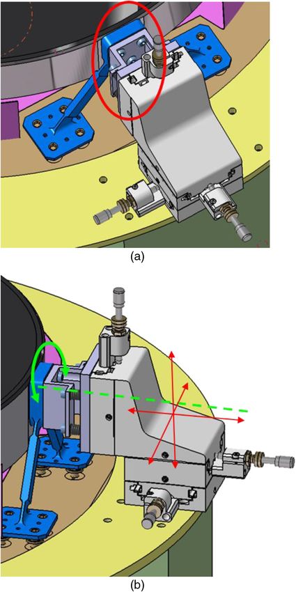
Lin et al.: Alignment and assembly process for primary mirror subsystem of a spaceborne telescope

                                                                                                  Fig. 3 Adjustment mechanism of bipod flexure bonding MGSE.
                                                                                                  (a) Components of bipod flexure fixture and adjusting MGSE.
                                                                                                  (b) Concept of bipod flexure adjusting MGSE.

                                                                                                  2.3 þ ð1∕400Þ  L μm, where L is the length measured in
                                                                                                  millimeters. Before the M1 assembly, the manufacturer
                Fig. 2 Schematic drawing of the adjustment mechanism of the                       errors such as dimension and planarity errors of the bipod
                mechanical ground-supported equipment (MGSE) in the M1                            flexure and main plate shall be measured by CMM. As
                assembly process. (a) System overview of M1, bipod flexure, main                  the manufactured error was known, the description of a
                plate, and corresponding MGSE. (b) Mechanism of M1 posture                        mechanical compensated shim between the bipod flexure
                adjustment MGSE. (c) Alignment datum on main plate hanging
                MGSE supporter.                                                                   and main plate can be estimated before M1 assembly.
                                                                                                  This section states the preparation of the mechanical
                correct posture and controlled the bond line between M1.                          shim, the alignment procedure of M1, and the bonding pro-
                The bipod flexure adjusting MGSE was assembled with a                             cedure of bipod flexure (as shown in Fig. 4).
                three-axis translation stage as shown in Fig. 3.
                                                                                                  3.4 Description of Compensated Shim
                3.3 Alignment Procedure for the Primary Mirror and                                To compensate for the astigmatism caused by deformation of
                    Bipod Flexure                                                                 the lightweight mirror because of gravity, the center of mass
                In general, the accuracy of the CMM is determined by the                          of the bonding pad of the bipod flexure was targeted to
                measurement scale of the machine. The accuracy of the Leitz                       coincide with the plane through the center of gravity of
                PMM-F CMM, which was used in this study, was                                      the mirror (known as the neutral plane). To achieve this

                Optical Engineering                                                        115109-3                                 November 2015   •   Vol. 54(11)

Downloaded From: https://www.spiedigitallibrary.org/journals/Optical-Engineering on 21 Jan 2021
Terms of Use: https://www.spiedigitallibrary.org/terms-of-use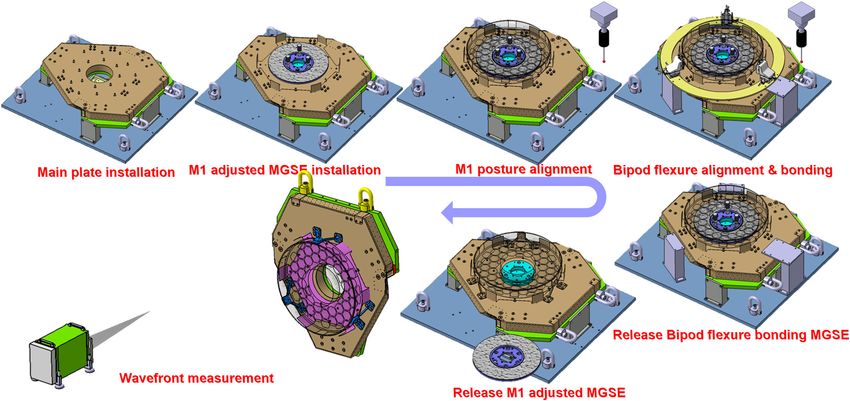
Lin et al.: Alignment and assembly process for primary mirror subsystem of a spaceborne telescope

                                                   Fig. 4 Flowchart of the M1 alignment and the bipod flexure bonding procedure.

                goal, the posture of the bipod flexure relative to the main                       the optical design software.12 The M1 alignment procedure
                plate was measured using a high-precision CMM. The                                is shown in Fig. 5.
                mechanical shim was the interface between the bipod flexure                           After completing the rough alignment, the fine alignment
                and the main plate to compensate for manufacturer errors                          was based on the foundation of the optical surface measure-
                that occurred in each component and for the differences                           ment of M1 conducted by the CMM. The layout of the mea-
                between the local coplanarity errors that occurred during                         sured point scheme was separated into 10 zones with an
                alignment. The mechanical shim used in this process                               equal arc length from point to point in each zone. After meas-
                could be separated into two parts: the solid shim, which                          urement, the contact point coordinate simulated by the CMM
                adjusted the bonding area of the bipod flexure to coincide                        was exported as a .txt file, and then the real contact point
                with the neutral plane of the mirror, and the 0.01-mm-                            coordinate can be compensated by a novel method with the
                thick shim rings, which compensated for manufacturer errors                       ray trace foundation on the optical software. Based on the
                and local coplanarity errors between the solid shim and base-                     compensated data, the optical surface parameter of the meas-
                plate of the bipod flexure. The solid shim was composed of                        urement was analyzed using the x-decenter, y-decenter,
                invar to prevent a mismatch of the bipod flexure thermal                          z-decenter, and radius results produced by the optimization
                expansion. The parameters of the shim rings were deter-                           of the optical software. In this method, the conic constant
                mined and calculated according to the dimensions of the                           is usually fixed, and the tilt is contributed as decenter.
                bipod flexure, the thickness of the solid shim, and the dis-                      According to the analyzed posture, the three high-resolution
                tance from the bonding area of the main plate to the reference                    screws adjusted the tilt less than 0.002 deg. The optimal
                on the back of the main plane measured by the CMM. As                             bonding position with minimal astigmatism of the primary
                shown in Table 1, B1 to B24 represent each interface of                           mirror caused by the gravity effect was simulated using
                the thread inserts of the main plate with respect to each                         the finite element method. The position of the bipod flexure
                bipod flexure. With the measured thickness of the solid                           was measured by the CMM and aligned to the correct posi-
                shim, bipod flexure dimension, and target height of the                           tion with an error of less than 0.01 mm in the axial and lateral
                bipod flexure relative to the main plate, the thickness of                        positions. The bipod flexure was then integrated onto the
                the shim ring (shown in the “Thickness of compensated                             main plate by using a torque wrench accompanied by strain
                shim” column in Table 1) was easily calculated before                             gauge monitoring to measure any abnormal deviations.
                bipod flexure installation. Table 1 shows that the deviation                      Figure 6 illustrates the status of the primary mirror alignment
                of the target value from the reference plate of the main plate                    process by using CMM.
                to the solid shim was less than 0.008 mm.
                                                                                                  3.6 Bonding Process for the Bipod Flexure
                3.5 Procedure for Aligning the Primary Mirror and                                 After using bond line control to conduct fine alignment of the
                     Bipod Flexure to the Main Plate                                              primary mirror and bipod flexure, 3M EC 2216 adhesive was
                The posture of the primary mirror was determined by the                           injected into the gap between the mirror and bipod flexure.
                optical axis rather than the geometry of the primary mirror.                      Before adhesive injection, treatments to prevent pollution of
                A Leitz PMM-F 30.20.16 CMM was used to measure the                                the optical surface and bipod flexure were performed. The
                profile of the optical surface and the coordinations of the                       bonding surfaces of M1 and the bipod flexure were carefully
                contacted point measurement were then used to fit the radius,                     cleaned, and primers were painted on the bonding surfaces of
                conic constant, and the posture parameters based on the least                     the primary mirror and bipod flexure to maintain a bonding
                square fitting. Thus, decenter and tilt relative to the main                      force. A dental mirror was used to ensure that the gap was
                plate were also analyzed using the macro developed by                             completely filled with adhesive. A wavefront sensor

                Optical Engineering                                                        115109-4                                  November 2015    •   Vol. 54(11)

Downloaded From: https://www.spiedigitallibrary.org/journals/Optical-Engineering on 21 Jan 2021
Terms of Use: https://www.spiedigitallibrary.org/terms-of-use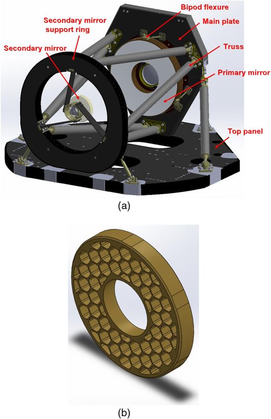
Lin et al.: Alignment and assembly process for primary mirror subsystem of a spaceborne telescope

                             Table 1 Description of the mechanical compensated shim and estimated height of bipod flexure relative to main plate.

                                                                                                                              Compensated height of solid shim
                                                                                                      Thickness of
                                                                Height of solid     Bipod flexure     compensated      Z  PA_PXPZ PA_PYPZ             Div.
                                                  No. insert     shim (mm)          height (mm)        shim (mm)     (mm)   (deg)   (deg)            (mm) Parallelism

                Bipod flexure III    Interface        B1            63.827             94.959            0.801       63.820    90.030      90.000   −0.007     0.076
                                         1            B2            63.827                               0.806

                                                      B3            63.827                               0.767

                                                      B4            63.827                               0.779

                                     Interface        B5            63.801             94.985            0.804       63.799    89.990      89.994   −0.002
                                         2            B6            63.801                               0.801

                                                      B7            63.801                               0.766

                                                      B8            63.801                               0.788

                Bipod flexure I      Interface       B9             63.823             94.963            0.556       63.824    89.992      90.011   0.001      0.007
                                         3           B10            63.823                               0.555

                                                     B11            63.823                               0.539

                                                     B12            63.823                               0.548

                                     Interface       B13            63.821             94.965            0.530       63.816    89.996      90.013   −0.005
                                         4           B14            63.821                               0.542

                                                     B15            63.821                               0.533

                                                     B16            63.821                               0.547

                Bipod flexure II     Interface       B17            63.798             94.988            0.603       63.792    90.002      89.976   −0.006     0.136
                                         5           B18            63.798                               0.582

                                                     B19            63.798                               0.604

                                                     B20            63.798                               0.582

                                     Interface       B21            63.795             94.991            0.522       63.802    89.953      90.045   0.007
                                         6           B22            63.795                               0.502

                                                     B23            63.795                               0.529

                                                     B24            63.795                               0.510

                                              Fig. 5 Schematic drawing of the M1 alignment and the bipod flexure bonding procedure.

                Optical Engineering                                                        115109-5                                      November 2015   •   Vol. 54(11)

Downloaded From: https://www.spiedigitallibrary.org/journals/Optical-Engineering on 21 Jan 2021
Terms of Use: https://www.spiedigitallibrary.org/terms-of-use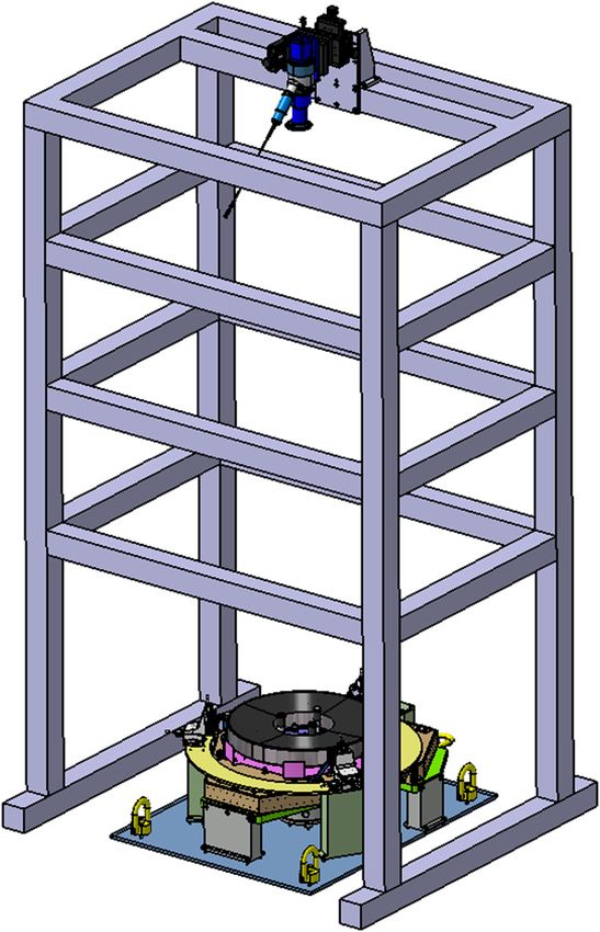
Lin et al.: Alignment and assembly process for primary mirror subsystem of a spaceborne telescope

                Fig. 6 Status of alignment process for the primary mirror by using
                coordinate measuring machine (CMM).

                measurement system (wavefront sensor with an autocollima-
                tor and a compatible focusing module) and strain gauge were
                used to monitor the wavefront and strain variation while the
                adhesive cured, as shown in Fig. 7. Figure 8 illustrates the
                relative measurement during wavefront error monitoring,
                and Fig. 8(b) is the wavefront map subtracted from the
                map from Fig. 8(a) as the zero point before monitoring.
                Figure 8(c) shows the wavefront error deviation after EC
                2216 was cured after 120 h. Figure 9–12 is the comparison
                of the wavefront deviation of the specified Zernike coefficient

                                                                                                  Fig. 8 Wavefront error map of wavefront sensor monitoring after EC
                                                                                                  2216 injection process. (a) Wavefront error map of M1 measured by
                                                                                                  wavefront sensor. (b) Subtracted wavefront error as reference before
                                                                                                  monitoring. (c) Wavefront error deviation within 120 h.

                                                                                                  when EC 2216 was cured for 132 h; it can be obviously found
                                                                                                  out that there was a slight trefoil caused from the shrinkage of
                Fig. 7 Illustrations of experimental setup for wavefront sensor mon-              the epoxy. Moreover, the induced coma may be contributed by
                itoring after EC 2216 injection in bipod flexure bonding process.                 misalignment from the wavefront sensor and primary mirror

                Optical Engineering                                                        115109-6                                     November 2015    •   Vol. 54(11)

Downloaded From: https://www.spiedigitallibrary.org/journals/Optical-Engineering on 21 Jan 2021
Terms of Use: https://www.spiedigitallibrary.org/terms-of-use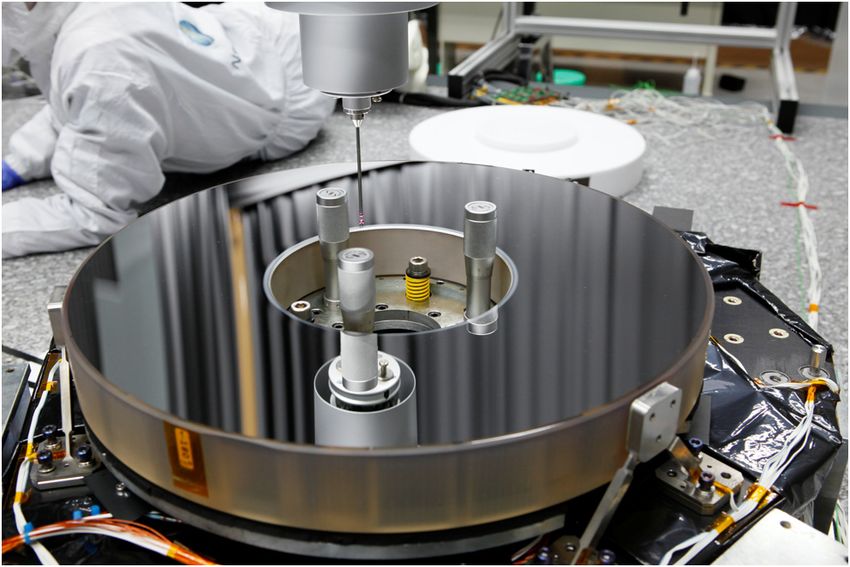
Lin et al.: Alignment and assembly process for primary mirror subsystem of a spaceborne telescope

                                            Fig. 9 Monitoring the astigmatism variation during the EC 2216 curing process within 120 h.

                                               Fig. 10 Monitoring the trefoil variation during the EC 2216 curing process within 120 h.

                                          Fig. 11 Monitoring the coma and tilt variation during the EC 2216 curing process within 120 h.

                                          Fig. 12 Comparison of the wavefront variation during the EC 2216 curing process within 132 h.

                caused from the displacement of the metrology frame due to                        used to confirm the posture of M1 after the supporting
                thermal effects (as shown in Fig. 11).                                            MGSE was completely released. The changes in the posture
                                                                                                  of M1 and the bipod flexure are shown in Tables 2 and 3.
                4 Results and Discussion                                                          Table 2 shows that even though the alignment error devia-
                                                                                                  tions of M1 and the bipod flexure were less than
                4.1 Posture Deviation of the M1 and Bipod Flexure                                 0.005 mm in the alignment phase, a little movement was gen-
                    in Assembly Process                                                           erated because the adhesive shrank during the curing and
                After the adhesive was completely cured, the M1 posture                           supporting MGSE removal phases. The deviation of the opti-
                adjustment MGSE was disassembled. The CMM was                                     cal axis of the primary mirror was less than 0.004 deg. The

                Optical Engineering                                                        115109-7                                 November 2015   •   Vol. 54(11)

Downloaded From: https://www.spiedigitallibrary.org/journals/Optical-Engineering on 21 Jan 2021
Terms of Use: https://www.spiedigitallibrary.org/terms-of-use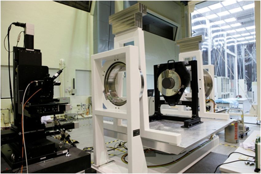
Lin et al.: Alignment and assembly process for primary mirror subsystem of a spaceborne telescope

                                              Table 2 Deviation of position of M1’s posture during the bipod flexure bonding process.

                                                         Release bipod flexure
                                     After fine       mechanical ground-supported            Gluing            Release                           Offset
                                     alignment            equipment (MGSE)                  EC 2216            MGSE              Div.         coordination           Div.

                X -decenter           −0.0040                        NA                       0.0501             0.0491        −0.0010         −0.0009             −0.0009

                Y -decenter            0.0002                        NA                      −0.0212             0.0162        0.0374           0.0047              0.0047

                Z (mm)               147.9913                     −0.0090                   147.9933          147.9632         −0.0371         147.9616            −0.0387

                Tilt-X (deg)          −0.0019                     −0.0019                    −0.0015           −0.0026         −0.0011          0.0022              0.0036

                Tilt-Y (deg)           0.0003                      0.0003                     0.0019             0.0031        0.0013           0.0016             −0.0003

                Rotated              179.9962                        NA                     179.9972          179.9972         −0.0028          0.0016             −0.0016
                angle (deg)

                                                  Table 3 Deviation of position of bipod flexure’s posture during bonding process.

                                                                            Distance from bipod flexure to M1 apex.                                                 Div.

                Unit (mm)                       Target value          Alignment level             After release MGSE          Offset coordination            Refer to target

                Bipod flexure No. 1               10.7657                 10.7570                      10.7574                      10.7583                        −0.0074

                Bipod flexure No. 2               10.7657                 10.7550                      10.7609                      10.7607                        −0.0050

                Bipod flexure No. 3               10.7657                 10.7580                      10.7638                      10.7632                        −0.0025

                bonding position from the top surface of each bipod flexure                         (Aberrationbond ) can be obtained by the aberration with
                relative to the apex of M1 during the whole bipod flexure                           the mirror rotated (Aberrationrotated ) minus the aberration
                bonding process is shown in Table 3. Deviation from the                             from the manufacturing stage. The aberrations caused by the
                theoretical target value was maintained within 0.008 mm                             gravity effect could also be analyzed according to the sym-
                by using the alignment process and designed MGSE.                                   metry of the lightweight scheme on the backside of the
                                                                                                    mirror with a period of 60 deg. Moreover, the intrinsic sys-
                                                                                                    tematic error of the wavefront sensor can be determined as
                4.2 Optical Test with Wavefront Sensor                                              the bias of the overall bench test. The nonrotational Zernike
                Wavefront measurement is an appropriate method for veri-                            coefficients of the various orientations of the primary mirror
                fying whether the bipod flexure bonding process is suitable.                        grabbed from the wavefront sensor can be plotted directly
                A wavefront sensor with a 128 × 128 spatial resolution, auto-                       with a continuous curve as shown in Fig. 14. The rotational-
                collimator, compatible focusing module, five-axis motorized                         symmetric aberration (spherical aberration) is nonsensitive
                stage system, and two-axis rotation gimbal were used during                         for the gravity effect and mounting force; thus it can be
                this step. Figure 13 shows the configuration of the setup for                       neglected in this case.
                the optical performance test. The analysis method called a
                bench test was performed according to the characteristics of
                the Zernike polynomial. Although the measurement was
                conducted by a wavefront sensor, the results could also be
                output as fringe Zernike coefficients to identify the form
                error of the component or system aberrations. This method
                adopts the frequency of peaks and valleys of each fringe
                Zernike coefficient grabbed by the measurement with vari-
                ous orientations in a horizontal optical-axis configuration to
                separate the nonrotationally symmetric aberration of the mir-
                ror.12 Based on the characteristics of each fringe Zernike
                term, the aberration from the residual form error after manu-
                facturing was obtained before the bipod flexure bonding
                process. During the bench test, after the bipod flexure was
                bonded to the primary mirror, only form errors caused by
                manufacturing with mounting effects rotated as the mirror
                rotated, but the gravity effect and intrinsic systematic error                      Fig. 13 Experimental setup for the optical performance test after pri-
                did not. Therefore, the aberrations caused by the mount                             mary mirror assembly.

                Optical Engineering                                                        115109-8                                        November 2015       •   Vol. 54(11)

Downloaded From: https://www.spiedigitallibrary.org/journals/Optical-Engineering on 21 Jan 2021
Terms of Use: https://www.spiedigitallibrary.org/terms-of-use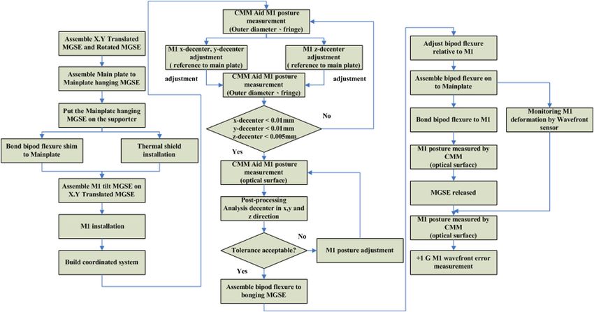
Lin et al.: Alignment and assembly process for primary mirror subsystem of a spaceborne telescope
pffiffiffiffiffiffiffiffiffiffiffiffiffiffiffiffi
The posted analysis method for the absolute measurement C¼
EQ-TARGET;temp:intralink-;e002;326;752 A2 þ B 2 ; (2)
is based on Zernike polynomials, which are an orthogonal set
of polynomials with variables in radial, r, and azimuthal, θ,
extent. A complete mathematical description for a given sur-
face, ΔZðr; θÞ, is obtained by 1 −1 B
δ ¼ tan : (3)
m A
EQ-TARGET;temp:intralink-;e003;326;716
X
∞
ΔZðr; θÞ ¼ A00 þ An0 R0n ðrÞ
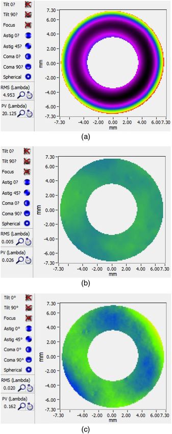
Figure 14 shows the plotted curve for the astigmatism, tre-
EQ-TARGET;temp:intralink-;e001;63;697
n¼2
foil, and tetrafoil terms. The obtained fringe Zernike coeffi-
∞ X
X n
cient with astigmatism terms of various orders consisted of
þ Rm
n ðrÞ½Anm cosðmθÞ
the residual form error after manufacturing, mounting effect,
n¼1 m¼1
gravity effect, and system calibration error. These errors
þ Bnm sinðmθÞ: (1) meant that the characteristics of the measured astigmatism
term were not exactly the same as the theoretical value,
Each of the Zernike terms is a function of phase angle δ, such which was 180 deg. By contrast, the measured trefoil terms
as tilt and astigmatism, and has a cosine and sinusoidal also consisted of the residual form error after manufacturing,
dependence, represented by the Zernike coefficients A and mounting effect, gravity effect, and system calibration error,
B, respectively. Each pair of terms may be expressed as a but the characteristics of the measured trefoil term were
single term with an associated magnitude C and phase δ, almost the same as the theoretical value, which was
expressed as follows: 120 deg. This phenomenon suggested that the form error
Fig. 14 Curve graph plotted by the Zernike coefficient gained from a bench test with different orientations
of the primary mirror.
Optical Engineering 115109-9 November 2015 • Vol. 54(11)
Downloaded From: https://www.spiedigitallibrary.org/journals/Optical-Engineering on 21 Jan 2021
Terms of Use: https://www.spiedigitallibrary.org/terms-of-useLin et al.: Alignment and assembly process for primary mirror subsystem of a spaceborne telescope
Table 4 Analyzed surface figure caused by manufacturer and deformation due to the mount and gravity effect.
Fringe Zernike coefficient Aberrationgravity Aberrationconstant Aberrationrotated Aberrationbond
Magnitude (wave at 632.8 nm) Pri astigmatism 0.019 0.014 0.040 0.016
Pri coma 0.008 0.006 0.009 0.009
Pri trefoil 0.008 0.052 0.085 0.044
Sec astigmatism 0.015 0.007 0.023 0.030
Sec coma 0.003 0.006 0.006 0.016
Pri tetrafoil 0.003 0.004 0.012 0.017
Sec trefoil 0.002 0.006 0.015 0.018
Third astigmatism 0.006 0.011 0.009 0.008
Phase (deg) Pri astigmatism −1.239 −18.954 66.798 28.372
Pri coma 52.634 37.502 −19.017 −19.017
Pri trefoil −39.354 21.080 −56.544 −45.214
Sec astigmatism 2.488 78.559 53.787 46.847
Sec coma 19.831 −162.644 135.654 175.016
Pri tetrafoil 16.050 25.822 36.457 32.406
Sec trefoil 33.911 −42.313 10.122 19.364
Third astigmatism −83.770 −3.705 −24.574 −37.497
with the mounting effect dominated the measured results References
and the trefoil was less sensitive to the gravity effect. 1. E. F. Howick, D. Cochrane, and D. Meierc, “Using a co-ordinate meas-
According to the characteristics of the Zernike coefficient, uring machine to align multiple element large optical systems,” Proc.
the algorithm can be used to analyze the surface figure SPIE 6676, 66760L (2007).
2. P. R. Yoder, Opto-Mechanical Systems Design, pp. 21–31, Marcel
caused by intrinsic systematic error (Aberrationconstant ) and Dekker Inc., New York (1993).
deformation caused by the mount (Aberrationbond ) and grav- 3. H. P. Stahl et al., “Survey of interferometric techniques used to test
ity effects (Aberrationgravity ). Table 4 shows a comparison of JWST optical components,” Proc. SPIE 7790, 779002 (2010).
4. C. Wells et al., “Primary mirror segment assembly integration and
the measured results as fringe Zernike coefficients. alignment for the James Webb Space Telescope,” Proc. SPIE 7793,
779309 (2010).
5. W.-C. Lin et al., “The alignment of the aerospace Cassegrain telescope
primary mirror and iso-static mount by using CMM,” Proc. SPIE
5 Conclusion 8131, 81310M (2011).
6. W.-C. Lin et al., “The alignment and iso-static mount bonding tech-
A CMM is an excellent tool to assist with aligning the pri- nique of the aerospace Cassegrain telescope primary mirror,” Proc.
mary mirror with respect to the main plate and aligning the SPIE 8491, 84910M (2012).
bipod flexure to the correct bonding position. It can be obvi- 7. H. Kihm et al., “Adjustable bipod flexures for mounting mirrors in a
space telescope,” Appl. Opt. 51(32), 7776–7783 (2012).
ously found that there was a slight trefoil with P–V 0.034 λ at 8. Y. C. Lin et al., “Optimization and analysis of the primary mirror
632.8 nm caused from the shrinkage of the EC 2216 cured mounting position for Cassegrain telescope,” in Proc. 2012 Int.
Conf. Convergence Information Technology (ICCIT 2012), Lect.
for 132 h. Moreover, the aberration caused by the external Notes Inf. Technol., Vol. 19, pp. 53–58 (2012).
force can be analyzed efficiently based on the theory of 9. H. P. Stahl et al., “Design for an 8-meter monolithic UV/OIR space
the bench test. As the final result, the designed MGSE telescope,” Proc. SPIE 7436, 743609 (2009).
10. J. W. Zinn and G. W. Jones, “Kepler primary mirror assembly: FEA
successfully adjusted the posture of the primary mirror surface figure analyses and comparison to metrology,” Proc. SPIE
closed to the tolerance of the telescope. The bipod flexure 6671, 667105 (2007).
was then bonded to the correct position to produce a 11. W.-C. Lin et al., “Comparing optical test methods for a lightweight
primary mirror of a space-borne Cassegrain telescope,” Meas. Sci.
small astigmatism aberration of P–V 0.0188 λ at 632.8 nm. Technol. 25, 094014 (2014).
This aberration was caused by gravity. The astigmatism aber- 12. S. T. Chang et al., “Measurement of radius of curvature by coordinate
measurement machine,” Appl. Mech. Mater. 284–287, 488–492
ration from mounting or bonding was approximately P–V (2013).
0.0156 λ at 632.8 nm. Moreover, the trefoil aberration due
to the bond analyzed by the bench test is consistent with Wei-Cheng Lin is a PhD graduate student in the Department of
the monitoring wavefront deviation with the wavefront sen- Power Mechanical Engineering at the National Tsing Hua University.
He is currently an associate engineer at the Instrument Technology
sor. The above-mentioned result indicates that a suitable pri- Research Center, National Applied Research Laboratories. His
mary mirror assembly process minimized the astigmatism research interests are optomechanical design, optomechanical system
caused by the mounting effect. assembly, CMM measurement, and optical testing.
Optical Engineering 115109-10 November 2015 • Vol. 54(11)
Downloaded From: https://www.spiedigitallibrary.org/journals/Optical-Engineering on 21 Jan 2021
Terms of Use: https://www.spiedigitallibrary.org/terms-of-useLin et al.: Alignment and assembly process for primary mirror subsystem of a spaceborne telescope
Shenq-Tsong Chang received his MS degree in physics from the Technology Research Center, National Applied Research
Catholic University of America. He is currently an associated Laboratories. His research interests are optomechanical design
researcher at the Instrument Technology Research Center, National and finite element analysis.
Applied Research Laboratories. His research interests are optical
design, CMM measurement, optical testing, and performance evalu- Chi-Chieh Chin is currently a vice technical engineer at the National
ation of optical systems. Space Organization, and National Applied Research Laboratories.
Sheng-Hsiung Chang is currently a vice technical engineer Hsu-Pin Pan received his MS degree from the State University of
at the National Space Organization, National Applied Research New York, Buffalo. He is currently a researcher at the Instrument
Laboratories. Technology Research Center, National Applied Research
Laboratories.
Chen-Peng Chang is currently a principal engineer at the National
Space Organization, National Applied Research Laboratories. Ting-Ming Huang received his PhD in aeronautics and astronautics
from the National Cheng Kung University. He is currently a research
Yu-Chuan Lin is a PhD graduate student in the Department of fellow and division director at the Instrument Technology Research
Engineering Science and Ocean Engineering at the National Taiwan Center, National Applied Research Laboratories.
University. He is currently an associate researcher at the Instrument
Optical Engineering 115109-11 November 2015 • Vol. 54(11)
Downloaded From: https://www.spiedigitallibrary.org/journals/Optical-Engineering on 21 Jan 2021
Terms of Use: https://www.spiedigitallibrary.org/terms-of-useYou can also read