Graphics processing unit-based implementation of a one-dimensional novel-look-up-table for real-time computation of Fresnel hologram patterns of ...
←
→
Page content transcription
If your browser does not render page correctly, please read the page content below

Graphics processing unit-based
                 implementation of a one-dimensional
                 novel-look-up-table for real-time
                 computation of Fresnel hologram
                 patterns of three-dimensional objects

                 Min-Woo Kwon
                 Seung-Cheol Kim
                 Eun-Soo Kim

Downloaded From: https://www.spiedigitallibrary.org/journals/Optical-Engineering on 25 Aug 2021
Terms of Use: https://www.spiedigitallibrary.org/terms-of-use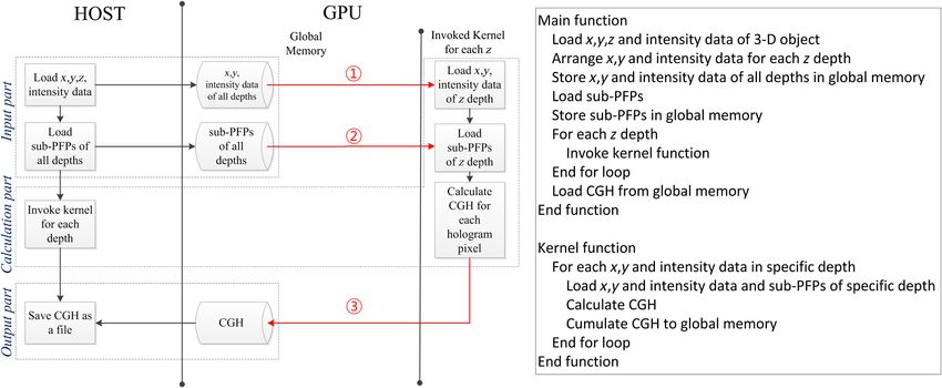
Optical Engineering 53(3), 035103 (March 2014)

                Graphics processing unit-based implementation of
                a one-dimensional novel-look-up-table for real-time
                computation of Fresnel hologram patterns of
                three-dimensional objects
                Min-Woo Kwon, Seung-Cheol Kim, and Eun-Soo Kim*
                Kwangwoon University, HoloDigilog Human Media Research Center, 3D Display Research Center, Department of Electronic Engineering,
                447-1 Wolgye-Dong, Nowon-Gu, Seoul 139-701, Republic of Korea

                              Abstract. A one-dimensional novel-look-up-table (1-D N-LUT) has been implemented on the graphics process-
                              ing unit of GTX 690 for the real-time computation of Fresnel hologram patterns of three-dimensional (3-D)
                              objects. For that, three types of optimization techniques have been employed, which include the packing tech-
                              nique of input 3-D object data and the managing techniques of on-chip shared memory and registers.
                              Experimental results show that the average hologram calculation time for one object point of the proposed sys-
                              tem has been found to be 0.046 ms, which confirms that the proposed system can generate almost 3 frames of
                              Fresnel holograms with 1920 × 1080 pixels per second for a 3-D object with 8000 object points. © The Authors.
                              Published by SPIE under a Creative Commons Attribution 3.0 Unported License. Distribution or reproduction of this work in whole or in part requires
                              full attribution of the original publication, including its DOI. [DOI: 10.1117/1.OE.53.3.035103]

                              Keywords: computer-generated hologram; novel-look-up-table; sub-principal fringe patterns; graphics processing unit.
                              Paper 131591 received Oct. 18, 2013; revised manuscript received Jan. 23, 2014; accepted for publication Feb. 12, 2014; published
                              online Mar. 17, 2014.

                1 Introduction                                                                      the conventional 2-D PFPs, which is called here 1-D N-LUT,
                Thus far, a number of approaches to accelerate the computa-                         has been proposed.3 In this 1-D N-LUT method, the GB
                tional time toward the real-time generation of computer-gen-                        memory of the conventional 2-D PFPs-based N-LUT,
                erated holograms (CGHs) have been proposed.1–16 One of                              which is called here 2-D N-LUT, could be dropped down
                them is the look-up-table (LUT) method.1 In this method,                            to the order of megabyte (MB) memory.3
                a significant increase of the computational speed has been                              In addition, for further reduction of the computational
                obtained by precalculating all fringe patterns corresponding                        time of the N-LUT, several software and hardware methods
                to point-source contributions from each of the possible loca-                       have been proposed.4–8 That is, in those software approaches,
                tions in the object volume, which are called elemental fringe                       including the spatial redundancy-based N-LUT,4 line redun-
                patterns (EFPs), and by storing them in the LUT. The great-                         dancy-based N-LUT,5 block redundancy-based N-LUT,6
                est drawback of this method, however, is the enormous                               as well as the temporal redundancy-based N-LUT,7 3-D
                memory capacity for the LUT.1                                                       object data to be calculated have been effectively reduced
                   Recently, a novel-LUT (N-LUT) to dramatically reduce                             by removing the spatial or temporal redundancy of the 3-D
                the required memory capacity along with maintaining the                             objects by using various image compression algorithms.
                fast computational speed was proposed.2 In this approach,                               Moreover, a couple of attempts to implement the conven-
                a three-dimensional (3-D) object is approximated as a set                           tional 2-D N-LUT on a field programmable gate array or a
                of discretely sliced object planes having different depths.                         graphics processing unit (GPU) has been done.9,10 But those
                Then, only the fringe patterns for the center-located object                        approaches were just trials to test the possibility of hardware
                points on each object plane, which are called two-dimen-                            implementation of the N-LUT, so they could not show any
                sional principal fringe patterns (2-D PFPs), are precalculated                      improvement in the computational speed.
                and stored in the N-LUT, so that the memory size of the                                 Until now, the commercial GPU boards with highly par-
                N-LUT could be reduced down to the order of gigabytes                               allel-computing architectures have been employed for accel-
                (GB) from the order of terabytes (TB) of the conventional                           erating the computational speed of several CGH generation
                LUT for the moderate 3-D object volumes.2                                           algorithms toward real-time applications.11–16
                   Basically, the memory capacity and the computational                                 For the N-LUT algorithm, simultaneous loading of a set of
                speed are the most challenging issues in the conventional                           PFPs as well as the input 3-D object data onto the internal
                N-LUT method. Therefore, several attempts to reduce the                             memory of the GPU is needed for the calculation of Fresnel
                memory capacity or to accelerate the computation time of                            hologram patterns, so that the memory and computing struc-
                the N-LUT have been made for its practical application.3–8                          ture of the GPU must be carefully evaluated for efficient
                   For further reduction of the memory, a new type of N-LUT                         implementation of the N-LUT on them. In this regard, the
                based on one-dimensional (1-D) sub-PFPs decomposed from                             conventional 2-D N-LUT requiring more than GB memory
                                                                                                    for storing the 2-D PFPs may not be compatible with
                                                                                                    the GPU having low-memory capacities. Furthermore, the
                *Address all correspondence to: Eun-Soo Kim, E-mail: eskim@kw.ac.kr                 memory and computing structure of the GPU need to be

                Optical Engineering                                                        035103-1                                                  March 2014     •   Vol. 53(3)

Downloaded From: https://www.spiedigitallibrary.org/journals/Optical-Engineering on 25 Aug 2021
Terms of Use: https://www.spiedigitallibrary.org/terms-of-use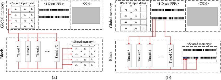
Kwon, Kim, and Kim: Graphics processing unit-based implementation of a one-dimensional novel-look-up-table. . .

                optimized for the fast algorithmic processing of the N-LUT                        and stored. Therefore, the unity-magnitude 2-D PFP for
                because of its limited memory capacity and bandwidth.                             the object point ð0; 0; zp Þ positioned on the center of an
                   Accordingly, in this article, we implement the 1-D                             object plane with a depth of zp , Tðx; y; zp Þ, can be defined
                N-LUT, maintaining a low-memory usage of megabytes,                               as follows:2
                on the commercial GTX 690 GPU board for the real-time
                computation of Fresnel hologram patterns of 3-D objects.                                              1
                For fast loading and accessing the sub-PFPs data of the 1-                        Tðx; y; zp Þ ≡         cos½krp þ kx sin θR þ φp :                                     (1)
                                                                                                                      rp
                D N-LUT and the 3-D data of the input object on the
                GPU board, three types of optimization techniques are
                employed, which include the packing technique of the                                 Here, the wave number k is defined as k ¼ 2π∕λ, in which
                input 3-D object data for efficient storing in the on-chip                        λ and θR represent the free-space wavelength of the light
                shared memory and the managing techniques of the on-                              and the incident angle of the reference beam, respectively.
                chip shared memory for fast computation of the CGH and                            The oblique distance rp between the p’th object point
                the on-chip registers for quick storing of the calculated holo-                   of ðxp ; yp ; zp Þ and the point on the hologram plane of
                gram data.                                                                        ðx; y; 0Þ is given by
                   Additionally, experiments with three kinds of test 3-D                                qffiffiffiffiffiffiffiffiffiffiffiffiffiffiffiffiffiffiffiffiffiffiffiffiffiffiffiffiffiffiffiffiffiffiffiffiffiffiffiffiffiffiffiffiffiffiffiffiffiffiffiffiffi
                objects are carried out with the proposed GPU-based 1-D                           rp ¼    ðx − xp Þ2 þ ðy − yp Þ2 þ z2p :                                                (2)
                N-LUT system, and the results are comparatively analyzed
                with those of the conventional central processing unit (CPU)-
                based 1-D N-LUT system in terms of the computational                                 Then, the fringe patterns of other object points on same
                speed.                                                                            object plane can be obtained by simply shifting this precal-
                                                                                                  culated 2-D PFP.2 Therefore, fringe patterns of all object
                                                                                                  points located on the same object plane can be generated
                2 Analysis of the 1-D and 2-D N-LUT Methods
                                                                                                  by adding these shifted versions of the 2-D PFP, and the
                2.1 Two-Dimensional N-LUT                                                         final CGH pattern for a 3-D object can be obtained by over-
                                                                                                  lapping all shifted versions of 2-D PFPs that are generated on
                As mentioned above, in the 2-D N-LUT method, the number                           each depth-dependent object plane.
                of fringe patterns to be stored in the N-LUT has been dra-                           Therefore, the CGH pattern for a 3-D object Iðx; yÞ in this
                matically reduced by employing a new concept of 2-D PFP.
                                                                                                  2-D N-LUT method can be expressed in terms of the shifted
                Geometry for generating the Fresnel hologram pattern of
                                                                                                  versions of precalculated 2-D PFPs of Eq. (1), as shown in
                a 3-D object is shown in Fig. 1 (Ref. 2).
                                                                                                  Eq. (3).
                    Here, the location coordinate of the p’th object point is
                specified by ðxp ; yp ; zp Þ, and each object point is assumed
                to have an associated real-valued magnitude and phase of                                        X
                                                                                                                N
                                                                                                  Iðx; yÞ ¼            ap Tðx − xp ; y − yp ; zp Þ;                                      (3)
                ap , φp , respectively. Also, the CGH pattern is assumed to                                     p¼1
                be positioned on the plane of z ¼ 0.
                    Actually, a 3-D object can be treated as a set of 2-D object
                planes discretely sliced along the depth direction of z. Each                     where N is the number of object points. Equation (3) shows
                object plane is approximated as a collection of self-luminous                     that the CGH pattern of a 3-D object can be obtained by just
                object points of light. In this 2-D N-LUT method, only the                        shifting the 2-D PFPs depending on the displaced values of
                fringe patterns of the center points on each image plane are                      the object points from the center object points on each object
                precalculated, which are called 2-D PFPs, and stored in con-                      plane and adding up them all.
                trary to the LUT method in which the fringe patterns for all                          Here, since the memory capacity of the 2-D N-LUT is
                possible object points, called 2-D EFPs, are precalculated                        calculated to be on the order of GB even for the moderate
                                                                                                  3-D object volume with image points of 320 × 240 × 256,
                                                                                                  in which 320, 240, and 256 denote the number of pixels
                                                                                                  in the horizontal, vertical, and depth directions, respectively,
                                                                                                  this 2-D N-LUT may not be well matched with the commer-
                                                                                                  cial GPU boards in terms of the computing and memory
                                                                                                  structures, which means that we could not expect an
                                                                                                  enhancement in the computational speed from this GPU-
                                                                                                  based 2-D N-LUT system.

                                                                                                  2.2 One-Dimensional N-LUT
                                                                                                  In the 1-D N-LUT method, 2-D PFPs of the conventional
                                                                                                  N-LUT can be decomposed into a pair of 1-D sub-PFPs
                                                                                                  by using a simple trigonometric relation. Therefore, these
                                                                                                  decomposed 1-D sub-PFPs, instead of the 2-D PFPs, are
                                                                                                  stored in the 1-D N-LUT for the CGH calculation of the
                                                                                                  3-D object, from which a remarkable memory reduction
                Fig. 1 Geometry for generating the Fresnel hologram pattern of                    of the 1-D N-LUT down to the order of MB could be
                a three-dimensional (3-D) object.                                                 obtained.3

                Optical Engineering                                                       035103-2                                                                March 2014   •   Vol. 53(3)

Downloaded From: https://www.spiedigitallibrary.org/journals/Optical-Engineering on 25 Aug 2021
Terms of Use: https://www.spiedigitallibrary.org/terms-of-use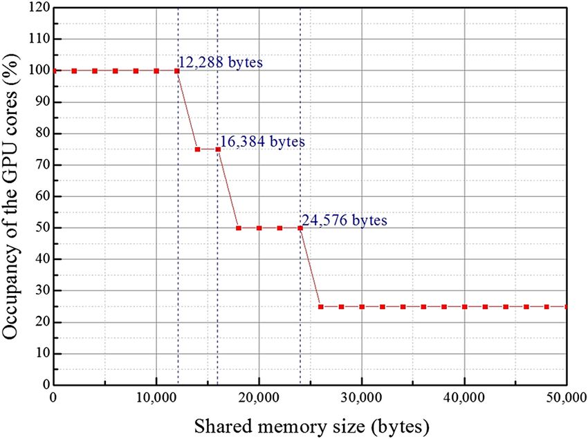
Kwon, Kim, and Kim: Graphics processing unit-based implementation of a one-dimensional novel-look-up-table. . .


                                    k                                                             Horizontal resolution of the 2-D PFPð2880Þ
                Tðx; y; zp Þ ¼ cos     ðΔx2 þ Δy2 þ z2p Þ
                                    zp                                                               ¼ horizontal resolution of the 3-D objectð320Þ
                                     2
                                       Δx Δy2 z2p z2p                                                  × intervals of the reconstructed image pointð30Þ∕
                             ¼ cos k        þ      þ þ
                                        zp    zp      2 2
                                    2                2                                             pixel pitch of the hologramð10Þ
                                       Δx z2p           Δy z2p
                             ¼ cos k        þ      þk        þ                                         þ horizontal resolution of the CGHð1920Þ
                                        zp    2           zp     2
                                    2             2                                       Vertical resolution of the 2-D PFPð1800Þ
                                       Δx zp  2
                                                             Δy z2p
                             ¼ cos k        þ       cos k         þ                                  ¼ vertical resolution of the 3-D objectð240Þ
                                        zp    2              zp     2
                                     2        2       2                                        × intervals of the reconstructed image pointð30Þ∕
                                        Δx zp                Δy z2p
                              − sin k       þ        sin k        þ      ;              (4)
                                         zp    2              zp    2                                    pixel pitch of the hologramð10Þ
                                                                                                       þ vertical resolution of the CGHð1080Þ:                  (5)
                where Δx ¼ x − xp and Δy ¼ y − yp . As you can see in
                Eq. (4), a 2-D PFP can be simply calculated by using a
                                                                                                     Therefore, the total memory capacity of the 2-D N-LUT is
                pair of 1-D sub-PFPs according to the trigonometric relation.
                    Figures 2(a) and 2(b) show a 2-D PFP and its 1-D version                      calculated to be 1.2 GB, as shown in Eq. (6).
                of a pair of sub-PFPs for a specific depth plane. For 256
                depth layers, 256 1-D sub-PFPs are stored in the 1-D
                                                                                                  Total memory capacity of the 2-D N-LUTð1.2 GBÞ
                N-LUT, whereas the same number of 2-D PFPs is stored
                in the 2-D N-LUT.                                                                    ¼ horizontal resolution of the 2-D PFPð2880Þ
                    For memory comparison, here we assume a 3-D object
                                                                                                       × vertical resolution of the 2-D PFPð1800Þ
                composed of plane images sliced with 256 levels along
                the depth direction, in which each plane image has a reso-                             × depth resolution of the 3-D objectð256Þ:               (6)
                lution of 320 × 240. In addition, the resolution of the CGH
                pattern to be generated is assumed to be 1920 × 1080 pixels,                         On the other hand, in the 1-D N-LUT method, to fully
                in which each pixel size is 10 × 10 μm2 . Also, it has been                       display the sub-PFP for the 3-D object volume having a res-
                well known that the human visual system usually sees as                           olution of 320 × 240 × 256 pixels, the 1-D PFP must be
                continuous two points that are separated by 3 mrad of                             shifted by 960 (320 × 3 ¼ 960) and 720 (240 × 3 ¼ 720)
                arc. Therefore, if the viewing distance is assumed to be                          pixels along the horizontal and vertical directions, respec-
                100 mm from the image plane, then the separation between                          tively. Thus, the resolution of a 1-D sub-PFP becomes
                two object points becomes 30 μm (100 mm × 0.003 ¼                                 2880 ð960 þ 1920 ¼ 2880Þ pixels, and as a result, the
                30 μm).1 Thus, the pixel size of hologram pattern of                              total memory capacity of the 1-D N-LUT is calculated to
                10 μm corresponds to the shift of 3 pixels. In other words,                       be 1.4 MB, as seen in Eq. (7).
                to display the two neighboring points to be seen as continu-
                ous, the PFP should be shifted by 3 pixels.2
                    Hence, to fully display the CGH pattern, the 2-D                              Total memory capacity of the 1-D N-LUTð1.4 MBÞ
                PFP must be shifted by 960 (320 × 3 ¼ 960) and 720                                   ¼ resolution of the 1-D PFPð2880Þ
                (240 × 3 ¼ 720) pixels along the horizontal and vertical
                directions, respectively, which means that the resolution of                           × the number of 1-D PFPsð2Þ
                a 2-D PFP becomes 2880 × 1800 pixels, as seen in Eq. (5).                              × depth resolution of the 3-D objectð256Þ:               (7)

                                                                                                     Accordingly, the memory size of the 1-D N-LUT has
                                                                                                  found to be almost 103 -fold smaller than that of the conven-
                                                                                                  tional 2-D N-LUT.

                                                                                                  3 Compatibility of the 1-D N-LUT with the GPU

                                                                                                  3.1 Memory Capacity
                                                                                                  In the N-LUT-based CGH generation method, a set of PFPs
                                                                                                  for the 3-D object must be precalculated and stored for
                                                                                                  calculation of the CGH patterns. That is, the N-LUT method
                                                                                                  needs a simultaneous loading of a set of PFPs as well as
                                                                                                  the input object data on the internal memory of the GPU.
                                                                                                  Basically, the memory size for the PFPs would be much larger
                                                                                                  than that for the object data, which means that the memory
                                                                                                  structure of the commercial GPU board must be carefully
                Fig. 2 Two-dimensional (2-D) PFP and its one-dimensional (1-D)                    evaluated for efficient implementation of the N-LUT on it.
                version of sub-PFPs: (a) 2-D PFP, and (b) 1-D sine and cosine                     Since a new type of N-LUT called 1-D N-LUT, which can
                sub-PFPs for a specific depth plane.                                              maintain a low-memory usage of megabytes as well as operate

                Optical Engineering                                                       035103-3                                       March 2014   •   Vol. 53(3)

Downloaded From: https://www.spiedigitallibrary.org/journals/Optical-Engineering on 25 Aug 2021
Terms of Use: https://www.spiedigitallibrary.org/terms-of-use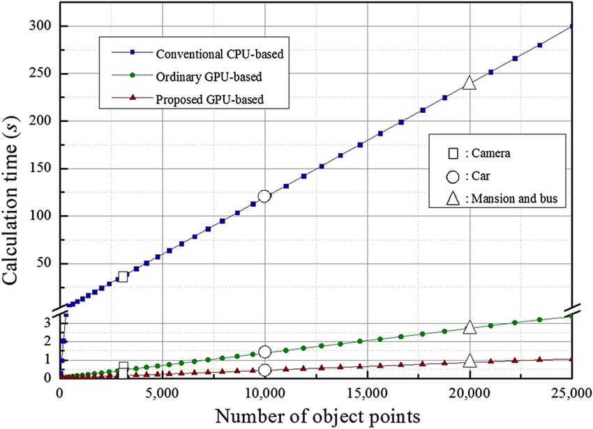
Kwon, Kim, and Kim: Graphics processing unit-based implementation of a one-dimensional novel-look-up-table. . .

                Table 1 Global memory specifications of various commercial GPUs.                     Even for the 3-D object volume having image points of
                                                                                                  4000 × 4000 × 256, only 6.8 MB memory is required for the
                                                                                                  1-D N-LUT, which is the sufficient amount of memory to be
                                     General-purpose GPU              Professional GPU
                                                                                                  fully stored in the global memories of the GTX GPU series
                               GTX       GTX      GTS      GT        Quadro                       with the maximum memory size of 2 GB. In other words, the
                               690       580      450      640        6000       TeslaK10         1-D N-LUT looks highly compatible with the commercial
                                                                                                  GTX GPU series, so that one of the general-purpose GPU,
                GDDR5            2       1.5        1        2          6             8
                memory
                                                                                                  the GTX 690 GPU, has been chosen here for implementation
                (GB)                                                                              of the 1-D N-LUT on it.

                                                                                                  3.2 Memory Structure
                on the 1-D data structure, is well matched with those of the
                commercial GPUs, here in this article, the 1-D N-LUT is                           In fact, the 1-D N-LUT has been developed for its implemen-
                employed for its implementation on the GPU board.                                 tation on the commercial GPU boards.3 That is, contrary to
                    Table 1 shows the GDDR5 (graphics double data rate,                           the conventional 2-D N-LUT, the memory and computing
                version 5) memory specifications in various commercial                            structures of the 1-D N-LUT are well matched with those
                GPUs.17–19 Here, the GDDR5 SDRAM is a type of high-                               of the GTX 690 GPU.17
                performance DRAM graphics memory card designed for                                    Generally, a GPU board supports several types of memo-
                                                                                                  ries that can be used by programmers to achieve a high
                the computer applications requiring a high bandwidth, which
                                                                                                  performance and thus a high-execution speed in their
                is the largest memory in the GPU called “global memory.”
                                                                                                  kernels. Figure 4 shows the memory structure and compute-
                Therefore, in the 1-D N-LUT method, sub-PFPs and object
                                                                                                  unified-device-architecture (CUDA) thread organization of
                data may be stored in this global memory of GDDR5
                                                                                                  the GTX 690 GPU.17 Here, in the CUDA thread organiza-
                SDRAM.                                                                            tion, the thread characterizes the fundamental means of
                    For example, the general-purpose GPU of GTX 690 and                           parallel execution in CUDA, and each block is composed of
                the professional GPU of Quadro 6000 have the global                               a group of threads. Moreover, the global memory shown at
                memories of 2 and 6 GB, respectively, as seen in Table 1.                         the bottom of Fig. 4 is written and read by the host by calling
                    Moreover, Fig. 3 shows the memory size dependence on                          application programming interface functions, but it has
                the resolution of the input object in both the 1-D and 2-D                        problems of long latency and limited bandwidth.
                N-LUT methods, in which the resolution of the hologram                                Hence, the GTX 690 GPU also supports the on-chip
                to be generated is assumed to be 1920 × 1080.                                     short-latency shared memory and registers. As shown in
                    For the 3-D object volume having image points of                              Fig. 4, variables that reside on those memories can be
                300 × 300 × 256, the total memories required in the 1-D and                       accessed at the very high speed in a highly parallel manner.
                2-D N-LUTs are calculated to be 1.38 MB and 1.33 GB,                                  Although these on-chip shared memory and registers can
                respectively. Moreover, they become 3.87 MB and 13.37 GB                          be effectively used for the reduction of the access number to
                for each case of the 1-D and 2-D N-LUTs for the 3-D object                        the global memory, one must be careful not to exceed the
                having the image points of 2000 × 2000 × 256. These results                       capacity of these memories. Each GPU device offers a lim-
                reveal that as the resolution of the input object increases, the                  ited amount of GPU memory, which may limit the number of
                corresponding memory size for the 2-D N-LUT gets sharply                          threads that can be simultaneously resided in multiprocessor
                increased according to the square-law on the GB range,                            for a given application.20
                whereas it may linearly increase on the MB range in the                               For the GTX 690 GPU board employed in this article, the
                1-D N-LUT.                                                                        total amount of shared memory per block (SMPB) and the
                                                                                                  total number of registers available per block are 49,152 bytes
                                                                                                  (48 kB) and 65,536 bytes (64 kB), respectively.17

                                                                                                  4 GPU-Based Implementation of the 1-D N-LUT

                                                                                                  4.1 Ordinary Implementation
                                                                                                  Figure 5 shows a basic software structure and pseudocode
                                                                                                  for implementation of the 1-D N-LUT on the GTX 690
                                                                                                  GPU board using the global memory, which is called here
                                                                                                  “Ordinary GPU-based 1-D N-LUT system.” It largely con-
                                                                                                  sists of three parts: Input, Calculation, and Output parts. That
                                                                                                  is, in the Input part, x, y, z coordinates and intensity data
                                                                                                  extracted from the input 3-D object and sub-PFPs of the
                                                                                                  1-D N-LUT are stored in the global memory of the GPU
                                                                                                  board. In the Calculation part, GPU kernel functions are
                                                                                                  invoked to load x, y coordinates and intensity data and
                                                                                                  sub-PFPs for specific z depth from the global memory
                                                                                                  and to calculate the CGH pattern. Furthermore, in the
                Fig. 3 Memory size dependence on the resolution of the input object               Output part, the calculated CGH pattern is saved and the
                in both the 1-D and 2-D N-LUTs.                                                   GPU kernel cumulates the calculated CGH patterns to

                Optical Engineering                                                       035103-4                                         March 2014   •   Vol. 53(3)

Downloaded From: https://www.spiedigitallibrary.org/journals/Optical-Engineering on 25 Aug 2021
Terms of Use: https://www.spiedigitallibrary.org/terms-of-use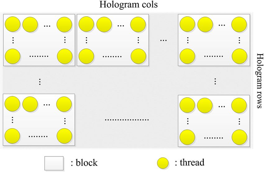
Kwon, Kim, and Kim: Graphics processing unit-based implementation of a one-dimensional novel-look-up-table. . .

                                                                 Fig. 4 Memory structure of the GTX 690 GPU board.

                the global memory. Right after these CGH calculations are                             In particular, since a large sub-PFPs data as well as the
                completed for all depth layers, the host computer loads the                       small object data are simultaneously stored in the global
                cumulated CGHs from the global memory and then the main                           memory of the GPU board from the host in the ordinary
                program may end.                                                                  GPU-based system as shown in ① and ② of Fig. 5, a kind
                   Actually, this basic software structure based on the global                    of traffic jams between the global memory and the threads
                memory of the GPU board has been employed in a couple of                          in the GPU may happen whenever the data are accessed,
                conventional GPU-based CGH generation methods.11,12                               because the global memory has the long-access latency as
                However, in this software structure of the ordinary GPU-                          well as the limited memory bandwidth. Moreover, whenever
                based system shown in Fig. 5, the fast-accessible on-chip                         the threads store the calculated results as shown in ③ of
                shared memory and registers of the GTX 690 GPU board                              Fig. 5, multiple write operations may occur between the
                may not be well managed for accelerated CGH calculations;                         threads and the global memory. It also causes the degradation
                so, an optimization process for efficient utilization of them is                  of the system performance.
                needed. Figure 5 shows the potential bottlenecks (①, ②, and                           Accordingly, if we can alleviate those bottlenecks men-
                ③) of this ordinary GPU-based system. That is, if the GPU                         tioned above, then the computational speed of the ordinary
                program is implemented only with the global memory, then it                       GPU-based system expects to be much enhanced. Therefore,
                may experience a traffic jam in loading and accessing the                         in this article three types of optimization techniques for data
                memory data, which may result in a degradation of the sys-                        loading and accessing in the GPU board are proposed. These
                tem performance.                                                                  will be discussed in detail later.

                                         Fig. 5 Basic software structure and pseudocode of the ordinary GPU-based 1-D N-LUT system.

                Optical Engineering                                                       035103-5                                        March 2014   •   Vol. 53(3)

Downloaded From: https://www.spiedigitallibrary.org/journals/Optical-Engineering on 25 Aug 2021
Terms of Use: https://www.spiedigitallibrary.org/terms-of-use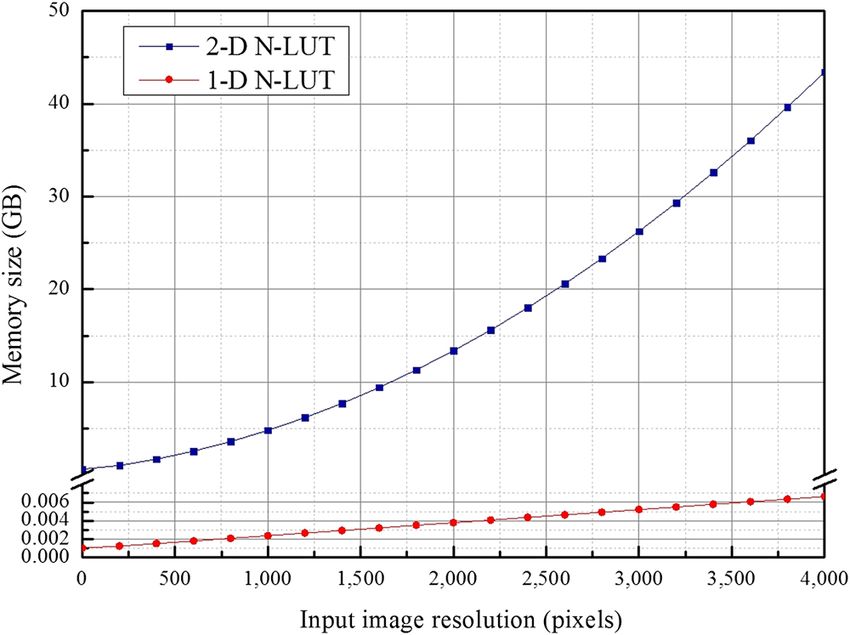
Kwon, Kim, and Kim: Graphics processing unit-based implementation of a one-dimensional novel-look-up-table. . .

                                                                                                  GTX 680 GPU boards, only one GTX 680 GPU board is
                                                                                                  employed in our experiment for just verifying the compati-
                                                                                                  bility of the 1-D N-LUT with the GPU. Moreover, we use
                                                                                                  only one CPU thread, in which this CPU was not used
                                                                                                  for CGH calculations but for controlling the software struc-
                                                                                                  ture such as loading the input images and N-LUT, controlling
                                                                                                  the GPU kernels, and saving the output holograms.
                                                                                                      Experimental results show that the average calculation
                                                                                                  times for one object point in the implemented ordinary
                                                                                                  GPU-based and the conventional CPU-based systems are
                                                                                                  estimated to be 0.143 and 11.956 ms, respectively. Here,
                Fig. 6 Intensity and depth images of the test objects of “Camera,”                the average calculation time for one object point of the
                “Car,” and “Mansion & Bus.”
                                                                                                  ordinary GPU-based system has been found to be 83-fold
                                                                                                  improved compared with that of the conventional CPU-
                   Here, the ordinary GPU-based 1-D N-LUT system                                  based system, but these results may say that the implemented
                employing the basic software structure of Fig. 5 is first                         ordinary GPU-based system still needs a further improvement
                implemented, and experiments are carried out for compari-                         in the computational speed for the real-time applications.
                son. Intensity and depth images of three test 3-D objects are
                shown in Fig. 6, which are used as the input object data
                for the generation of its CGH pattern on the implemented                          4.2 Proposed Implementation
                ordinary GPU-based system. In the experiments, three test                         Figure 7 shows an overall software structure and pseudocode
                objects of “Camera,” “Car,” and “Mansion & Bus” with                              of the proposed GPU-based 1-D N-LUT system, which is
                the same 3-D object volume of 320 × 240 × 256 pixels are                          called here “Proposed GPU-based 1-D N-LUT system.” In
                assumed to have object points of 3021, 9944, and 19,984,                          the proposed system, three types of optimization techniques
                respectively. Moreover, the CGH pattern to be generated                           to efficiently manage the on-chip shared memory and
                is assumed to have a resolution of 1920 × 1080 pixels, in                         registers of the GPU board are suggested for solving the
                which each pixel size is 10 × 10 μm2 , and the horizontal                         bottlenecks of the ordinary GPU-based system. Here, the
                and vertical discretization steps of less than 30 μm are chosen                   optimization techniques may depend on the employed CGH
                since the viewing distance is fixed to be 100 mm in the                           generation algorithms,16,21,22 so, in this article, new types of
                experiment.                                                                       memory managing techniques properly optimized to the 1-D
                   With these test object data and corresponding sub-PFPs,                        N-LUT are proposed.
                CGH patterns are calculated by using the implemented ordi-                            As shown in Fig. 7, in the Input part, the 3-D object data
                nary GPU-based 1-D N-LUT system. For comparison, the                              are packed together for efficient storing as much object data
                same calculations are also performed with the conventional                        as possible in the on-chip shared memory. In the Calculation
                CPU-based 1-D N-LUT system. Here, the computer system                             and Output parts, two memory managing techniques for
                used in the experiment is composed of an Intel i7 3770 CPU,                       utilizing both the fast-accessible on-chip shared memory
                an 8 GB RAM, and a GTX 690 GPU of NVIDIA, and it                                  and registers are used. These optimization techniques may
                works on the CentOS 6.3 Linux platform. Basically, even                           improve the performance of the proposed GPU-based 1-D
                though the GTX 690 GPU board is composed of two                                   N-LUT system.

                                        Fig. 7 Overall software structure and pseudocode of the proposed GPU-based 1-D N-LUT system.

                Optical Engineering                                                       035103-6                                         March 2014   •   Vol. 53(3)

Downloaded From: https://www.spiedigitallibrary.org/journals/Optical-Engineering on 25 Aug 2021
Terms of Use: https://www.spiedigitallibrary.org/terms-of-use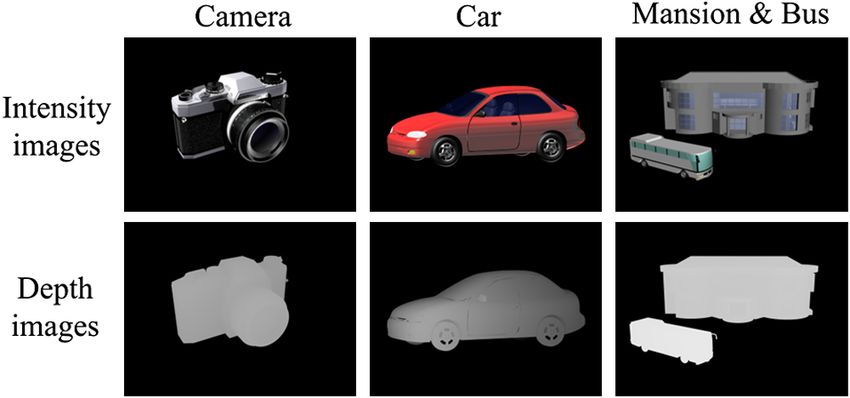
Kwon, Kim, and Kim: Graphics processing unit-based implementation of a one-dimensional novel-look-up-table. . .

                4.2.1 Operational design of the proposed system                                      Since the CGOC may select the smallest value of the AB
                In this article, the GPU board calculates the CGH at a high                       among three cases derived above, the AB is finally deter-
                speed in parallel by using the CUDA. The CUDA is a par-                           mined to be 4. Therefore, the value of active number of
                allel-computing platform and programming model invented                           WPM is calculated to be 64ð16 × 4 ¼ 64Þ through multipli-
                by the NVIDIA. It enables a dramatic enhancement of                               cation of this AB value to the WPB. Then, the active and the
                computing performance by harnessing the power of the                              maximum numbers of WPM become exactly the same, and
                                                                                                  this result confirms 100% ð64∕64 × 100 ¼ 100Þ occupancy
                GPU. In the CUDA, the computing performance of the
                                                                                                  of the GPU. These calculations explained above are auto-
                GPU depends on the occupancy of the GPU cores. In other
                                                                                                  matically performed by using the CGOC (CUDA GPU
                words, it may depend on how efficiently the GPU cores in
                                                                                                  OC).23 In short, the proposed GPU-based 1-D N-LUT sys-
                parallel are used.
                                                                                                  tem has been designed to work with 100% occupancy of
                    In this article, each thread of the GPU board calculates
                                                                                                  the GPU cores as well as to secure the maximum space of
                each pixel of the CGH. That is, a parallel-processing algo-
                                                                                                  the on-chip shared memory for simultaneous loading of x, y
                rithm can be implemented based on each pixel of the CGH.
                                                                                                  coordinates and intensity data extracted from the input 3-D
                Figure 8 shows how to perform the parallel processing based                       object and the sub-PFPs data for specific z depth.
                on each pixel of the CGH, in which “Hologram cols” and
                “Hologram rows” represent the column and row sizes of
                                                                                                  4.2.2 Optimization of the input part
                the CGH pattern, respectively. That is, one thread is allocated
                to one pixel of the CGH and several threads are grouped by                        In the ordinary GPU-based 1-D N-LUT system, x, y, z
                a block.                                                                          coordinates and intensity data extracted from the input 3-
                    Here, occupancy of the GPU cores is calculated by using                       D object as well as the sub-PFPs data are stored in the global
                the “CUDA GPU Occupancy Calculator (CGOC).”23 Input                               memory of the GTX 690 GPU. On the other hand, in the
                parameters of the CGOC include “threads per block (TPB),”                         proposed system as shown in Fig. 7, both of them are stored
                “registers per thread (RPT),” and “shared memory per block                        in the global memory temporary and in the on-chip
                (SMPB).” In the CGOC, occupancy of the GPU is evaluated                           shared memory, whenever the CGH calculation operation
                by the ratio between the active number of “warps per multi-                       starts.
                processor (WPM)” and the maximum number of WPM, in                                    Here, in order to maintain the designed 100% occupancy
                which the maximum number of WPM is 64 and the active                              of the GPU cores, the SMPB must be kept to not larger than
                number of WPM is obtained by multiplication of the number                         12,288 bytes ð49;152∕4 ¼ 12;288Þ as discussed above.
                of “warps per block (WPB)” to the number of “active block                         For the 3-D object volume with object points of 320 × 240 ×
                (AB).” Here, the WPB is evaluated by dividing the TPB with                        256 and the CGH pattern with a resolution of 1920 ×
                the “threads per warp (TPW),” in which the TPW is 32.                             1080 pixels, the resultant memory size of a pair of sub-
                    To get 100% occupancy of the GPU cores, the TPB, RPT,                         PFPs for specific z depth is calculated to be 5760 bytes
                and SMPB are determined to be 512, 19, and 12,288, respec-                        (2880 × 2 ¼ 5760). Then, for loading these sub-PFPs data
                tively. Here, the AB can be calculated with each of the TPB,                      of 5760 bytes onto the on-chip shared memory by using
                RPT, and SMPB.23 That is, if the TPB is 512, the AB is                            512 threads in parallel, 6144 bytes of the shared memory,
                calculated to be 4ð64∕16 ¼ 4Þ through division of the maxi-                       which is the multiple numbers of 512, must be needed.
                                                                                                  Therefore, the remaining portion of the shared memory of
                mum number of WPM by the number of WPB. For the
                                                                                                  6144ð12;288 − 6144 ¼ 6144Þ bytes can be allocated for
                case if the RPT is 19, AB is then calculated to be 5ð84∕16 ¼
                                                                                                  loading x, y coordinates and intensity data extracted from
                5.25Þ by dividing the “registers per multiprocessor (RPM)”
                                                                                                  the input 3-D object for specific z depth.
                with the “registers per block (RPB).” Moreover, if the
                                                                                                      Accordingly, in the proposed system, to store as many of
                SMPB is 12,288, then the AB is also calculated to be
                                                                                                  these data as possible in this limited on-chip shared memory,
                4ð49;152∕12;288 ¼ 4Þ through division of the “shared                              combined packing scheme of 3-D object data is proposed. In
                memory per multiprocessor (SMPM)” by the SMPB, in                                 the 1-D N-LUT method, a set of sub-PFPs corresponding to
                which the SMPM is 49,152.                                                         each depth layer is provided for the calculation of the CGHs
                                                                                                  of the 3-D object. The GPU kernel function may be invoked
                                                                                                  in relation to the depth layer, so that the x, y coordinates and
                                                                                                  intensity values can be arranged together as tables for each
                                                                                                  depth layer having their z coordinate values.
                                                                                                      Here, the input object data are packed in the 32-bit
                                                                                                  memory, in which x, y coordinate values and the intensity
                                                                                                  value are allocated to 24-bit and 8-bit of the memory, respec-
                                                                                                  tively. By using this packing scheme, the input image data for
                                                                                                  one object point could be reduced down to 4 bytes from 12ð4 ×
                                                                                                  3 ¼ 12Þ bytes because x, y coordinate values and the intensity
                                                                                                  value can be carried only by one 32-bit (4 bytes) memory.

                                                                                                  4.2.3 Optimization of the calculation part
                                                                                                  Compared with the ordinary system, in which x, y, z coor-
                                                                                                  dinates and intensity data extracted from the input 3-D object
                                                                                                  and 1-D sub-PFPs are stored on the global memory as shown
                     Fig. 8 Block thread-based parallel processing of the CGH.                    in Fig. 5, the proposed system utilizes the on-chip shared

                Optical Engineering                                                       035103-7                                        March 2014   •   Vol. 53(3)

Downloaded From: https://www.spiedigitallibrary.org/journals/Optical-Engineering on 25 Aug 2021
Terms of Use: https://www.spiedigitallibrary.org/terms-of-use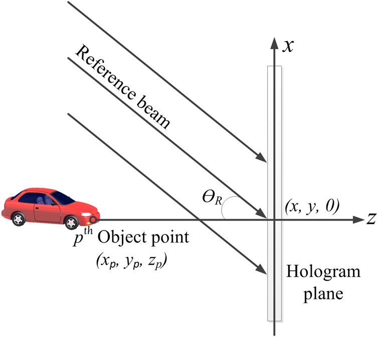
Kwon, Kim, and Kim: Graphics processing unit-based implementation of a one-dimensional novel-look-up-table. . .

                                       Fig. 9 Parallel storing of the sub-PFPs and the packed input object data to the on-chip shared memory:
                                       (a) storing of sub-PFPs, and (b) storing of the packed input object data.

                memory to fast access these data to the threads for acceler-                         Based on the equation of Fig. 10(a), “HOLOGRAM”
                ated computation of the CGH in the Calculation part, as                           denoting the CGH can be finally obtained, in which
                shown in Fig. 7. That is, the threads load the packed x, y                        “HOLOGRAM_INDEX” means the index of the CGH.
                coordinates and intensity data extracted from the input
                3-D object and the sub-PFPs for specific z depth from the                         4.2.4 Optimization of the output part
                global memory and save them onto the shared memory in                             Since in the ordinary GPU-based system, each thread calcu-
                parallel. Figure 9 shows the parallel loading process of                          lates one pixel of the hologram and directly cumulates
                these data from the global memory and saving them onto                            its result on the global memory, a tremendous number of
                the shared memory.                                                                read-write-operations may occur between the threads and
                   Figure 10 shows the implemented code for the calculation                       the global memory. Therefore, in the proposed system, for
                of the CGH pattern with the 1-D N-LUT. Here,                                      accelerated accumulation of the calculated CGH pattern,
                “PACKED_DATA” means the packed object data loaded                                 the on-chip registers are used for storing the calculated
                from the shared memory, which consist of x, y coordinates                         CGH, as shown in Fig. 7.
                and intensity values packed as one integer variable. Using                            That is, each thread calculates the CGH with x, y coor-
                a bit operation of the C-language, these three values                             dinates and intensity data extracted from the input 3-D object
                can be obtained as shown in Fig. 10(b). “PFP_X” and                               and the sub-PFPs for specific z depth and cumulates
                “PFP_Y,” representing the x, y coordinate values of the                           the results on the registers. In case of calculations for one
                1-D sub-PFP, respectively, can be obtained by using the                           depth layer end, each thread saves the cumulated results
                “MAGNIFICATION,” which is 3 pixels, and “OBJECT_X”                                onto the global memory. Therefore, the number of read-
                and “OBJECT_Y” denote the x, y coordinate values of the                           write-operations between the threads and the global memory
                input object, as shown in Fig. 10(b).                                             can be significantly reduced.
                   Then, “cos X,” “cos Y,” “sin X,” and “sin Y” repre-                                In the ordinary GPU-based system mentioned above, the
                senting four terms of the last line in Fig. 10(a), are obtained                   number of read-write-operations between the threads and the
                by using “COS subPFPs,” and “SIN subPFPs,” which are                              global memory to cumulate the calculated CGH pattern is
                a pair of 1-D sub-PFPs loaded from the shared memory.                             given by Eq. (8).

                                       Fig. 10 Implemented code for calculating the CGH with the 1-D N-LUT: (a) equation of 2-D PFP by using
                                       a pair of 1-D sub-PFPs, and (b) implemented code.

                Optical Engineering                                                       035103-8                                       March 2014   •   Vol. 53(3)

Downloaded From: https://www.spiedigitallibrary.org/journals/Optical-Engineering on 25 Aug 2021
Terms of Use: https://www.spiedigitallibrary.org/terms-of-use
Kwon, Kim, and Kim: Graphics processing unit-based implementation of a one-dimensional novel-look-up-table. . .
N Gmem ordinary system ¼ N Object × N Depth ; (8) for each case of the conventional CPU-based, the ordinary
GPU-based, and the proposed GPU-based systems. In other
where N Object and N Depth mean the numbers of input object words, the proposed GPU-based system has obtained 260
points and depth layers, respectively. On the other hand, in and threefold improvement of the average CGH calculation
the proposed GPU-based system, the number of read-write- time, respectively, compared with those of the conventional
operations between the threads and the global memory to CPU-based and the ordinary GPU-based systems.
cumulate the calculated CGH pattern can be given by Eq. (9). Here, the total CGH calculation time for the test 3-D
object of “Car” with 9944 object points is calculated to
N Gmem optimized system ¼ N Depth : (9) be 446 ms in the proposed system, which means that the pro-
posed system can generate 2.24 frames of the CGH patterns
Therefore, it has been found from Eqs. (8) and (9) that with 1920 × 1080 pixels per second.
the number of read-write-operations between the threads and These results may confirm the feasibility of the proposed
the global memory to cumulate the calculated CGH pattern GPU-based system in the practical applications. Moreover,
in the proposed method only depends on the number of depth the performance of the proposed system could be further
layers regardless of the number of input object points, improved through massive reduction of the input 3-D object
whereas it may depend on both the number of depth layers data by employing a concept of spatial and temporal redun-
and the number of input object points in the ordinary method. dancies as well as by multi-GPU-based implementation.
Figure 12 shows the total CGH calculation time depend-
5 Experimental Results and Discussions ence on the number of object points for each case of the
conventional CPU-based, the ordinary GPU-based, and
5.1 CGH Calculation Time the proposed GPU-based 1-D N-LUT methods, in which
Figure 11 shows the comparison results of the reconstructed the CGH resolution is set to be 1920 × 1080 and the number
test object images from the CGH patterns generated by each of object points is changed from 1 to 25,000.
of the conventional CPU-based, the ordinary GPU-based, For an input object volume with 10,000 object points, the
and proposed GPU-based 1-D N-LUT methods for three total CGH calculation time of the proposed system has been
test objects of “Camera,” “Car,” and “Mansion & Bus.” improved by 99.64% and 68.53% compared with those of
Here in the experiments, off-axis reference lights were the conventional CPU-based and the ordinary GPU-based
used for reconstruction of the object images without having systems, respectively. The results on the total calculation
direct and conjugate beams. As you can see in Fig. 11, all times for three test objects of “Camera,” “Car,” and
object images have been successfully reconstructed and “Mansion & Bus,” as shown in Table 2, are also included
visually look very well. in Fig. 12. As seen in Fig. 12, the results of Table 2 have
Table 2 shows the results of the average total CGH cal- been well matched with those of Fig. 12.
culation times and the average CGH calculation times for From Fig. 12, the total CGH calculation time for a 3-D
one object point for each method. As seen in Table 2, the object volume having 8000 object points has been estimated
average CGH calculation times for one object point are to be about 0.36, 1.10, and 94.71 s in the proposed, the ordi-
estimated to be 11.956, 0.143, and 0.046 ms, respectively, nary, and the conventional CPU-based systems, respectively,
Fig. 11 Comparison of input images and results on the reconstructed test object images from the con-
ventional CPU-based, the ordinary GPU-based, and the proposed GPU-based 1-D N-LUT methods.
Optical Engineering 035103-9 March 2014 • Vol. 53(3)
Downloaded From: https://www.spiedigitallibrary.org/journals/Optical-Engineering on 25 Aug 2021
Terms of Use: https://www.spiedigitallibrary.org/terms-of-useKwon, Kim, and Kim: Graphics processing unit-based implementation of a one-dimensional novel-look-up-table. . .
Table 2 Comparison results on the total CGH computation times and the average calculation times for one object point of each system for three
test objects.
Test object (number Total calculation Calculation time for
Implementation method of object points) time (ms) one point (ms)
Conventional CPU-based Camera (3021) 36,113 (100%) 11.954 (100%)
GPU-based Ordinary 457 (1.27%) 0.151 (1.27%)
Proposed 146 (0.40%) 0.048 (0.40%)
Conventional CPU-based Car (9944) 118,861 (100%) 11.953 (100%)
GPU-based Ordinary 1384 (1.16%) 0.139 (1.16%)
Proposed 446 (0.38%) 0.045 (0.38%)
Conventional CPU-based Mansion & bus (19,984) 239,056 (100%) 11.962 (100%)
GPU-based Ordinary 2751 (1.15%) 0.138 (1.15%)
Proposed 871 (0.36%) 0.044 (0.36%)
which means that the proposed system can generate 3 frames 5.3 Occupancy of the GPU Cores Depending on
of the CGH patterns with 1920 × 1080 per second, whereas the Shared Memory
the ordinary GPU-based and the conventional CPU-based Figure 13 shows the occupancy of the GPU cores depend-
systems can generate 1 and 0.01 frames of the CGH patterns ence on the shared memory size. As seen in Fig. 13, if
per second, respectively. the size of the shared memory for x, y coordinates and inten-
sity data extracted from the input 3-D object and sub-PFPs
data for specific z depth increases in the proposed system,
5.2 Achieved Occupancy of the GPU Cores then the occupancy of the GPU cores tends to be sharply
The NVIDIAVisual Profiler can be used for showing the real decreased even though the available shared memory space
occupancy value of the multiprocessor, which is called here for loading these data increases.
“achieved occupancy (AO).” The AO of the proposed GPU- That is, if the shared memory size to be used for these data
based system has been found to be 90.6%, which means gets increased up to 16,384, 24,576, and 30,000 bytes, exceed-
that the proposed system may operate with 90.6% of the ing its upper limit of 12,288 bytes for maintaining the designed
GPU cores. As discussed above, the proposed system has 100% occupancy of the GPU cores, then the corresponding
been designed to work with 100% occupancy of the GPU AB values decrease down to 3ð49;152∕16;384¼3Þ,
cores, but its real value in the implemented system has 2ð49;152∕24;579 ¼ 2Þ, and 1ð49;152∕30;000 ¼ 1.64Þ,
been evaluated to be a little bit lower than that. But this respectively. Then, their active numbers of WPM values
value of the AO may be generally acceptable in the real- also reduce to 48ð16 × 3 ¼ 48Þ, 32ð16 × 2 ¼ 32Þ, and
application fields.24 16ð16 × 1 ¼ 16Þ, respectively, which finally results in
Fig. 12 Results of calculation performance according to the number Fig. 13 Occupancy of the GPU cores dependence on the shared
of point and input objects. memory size.
Optical Engineering 035103-10 March 2014 • Vol. 53(3)
Downloaded From: https://www.spiedigitallibrary.org/journals/Optical-Engineering on 25 Aug 2021
Terms of Use: https://www.spiedigitallibrary.org/terms-of-useKwon, Kim, and Kim: Graphics processing unit-based implementation of a one-dimensional novel-look-up-table. . .
occupancy reduction of 75% ð48∕64 × 100 ¼ 75Þ, 50% 8. S.-C. Kim et al., “Fast generation of video holograms of three-dimen-
sional moving objects using a motion compensation-based novel
ð32∕64 × 100 ¼ 50Þ, and 25% ð16∕26 × 100 ¼ 25Þ, look-up table,” Opt. Express 21, 11568–11584 (2013).
respectively.23,24 9. D.-W. Kwon, S.-C. Kim, and E.-S. Kim, “Hardware implementation of
N-LUT method using field programmable gate array technology,”
That is, the more we use the on-chip shared memory of Proc. SPIE 7957, 79571C (2011).
the GPU board, the more we can store the input object and 10. Z. Ali et al., “Simplified novel look-up table method using compute
sub-PFPs data in this on-chip shared memory. On the other unified device architecture,” 3D Res. 2, 1–5 (2011).
11. X. Xu et al., “Computer-generated holography for dynamic display
hand, the corresponding occupancy of the GPU cores may of 3D objects with full parallax,” Int. J. Virtual Reality 8, 33–38
sharply decrease according to the size of the shared memory (2009).
used for the input object and sub-PFPs data, which means 12. Y. Pan et al., “Fast CGH computation using S-LUT on GPU,” Opt.
Express 17, 18543–18555 (2009).
that there might be a tradeoff between them. Accordingly, 13. Y. Liu et al., “A fast analytical algorithm for generating CGH of 3D
here in this article, the maximum space of the shared memory scene,” Proc. SPIE 7619, 76190N (2010).
for storing the input object and sub-PFPs data has been 14. Y.-Z. Liu et al., “High-speed full analytical holographic computations
for true-life scenes,” Opt. Express 18, 3345–3351 (2010).
limited to 12,288 bytes for maintaining the designed 100% 15. T. Shimobaba et al., “Rapid calculation algorithm of Fresnel computer-
occupancy of the GPU cores. generated-hologram using look-up table and wavefront-recording
plane methods for three-dimensional display,” Opt. Express 18,
19504–19509 (2010).
6 Conclusions 16. J. Weng et al., “Generation of real-time large computer generated holo-
In this article, we have implemented 1-D N-LUT on the GTX gram using wavefront recording method,” Opt. Express 20, 4018–4023
(2012).
690 GPU board by using three types of memory managing 17. NVIDIA GeForce series GTX690, GTX580, GTS450, GT 640, http://
techniques. Experiments with test 3-D objects show that the www.nvidia.com/object/geforce_family.html.
18. NVIDIA Quadro6000, http://www.nvidia.com/object/quadro.html.
average CGH calculation time for one object point of the 19. NVIDIA Tesla K10, http://www.nvidia.com/object/tesla-supercomputing-
implemented system has been calculated to be 0.046 ms, solutions.html.
which means that it could generate almost 3 frames of 20. W. Hwu and D. Kirk, “CUDA memories,” Chapter 5 in Programming
Massively Parallel Processors: A Hands-On Approach, pp. 77–93,
CGHs with 1920 × 1080 pixels per second for the 3-D Morgan Kaufmann, San Francisco (2010).
object with 8000 object points. Experimental results finally 21. T. Shimobada et al., “Fast calculation of computer-generated-hologram
on AMD HD5000 series GPU and OpenCL,” Opt. Express 18, 9955–
confirm the feasibility of the proposed system in the practical 9960 (2010).
applications. 22. N. Takada et al., “Fast high-resolution computer-generated hologram
computation using multiple graphics processing unit cluster system,”
Acknowledgments Appl. Opt. 51, 7303–7307 (2012).
23. NVIDIA CUDA Occupancy Calculator, http://developer.download
This work was supported by the National Research .nvidia.com/compute/cuda/3_1/sdk/docs/CUDA_Occupancy_
calculator.xls.
Foundation of Korea (NRF) grant funded by the Korea gov- 24. Private communications with a CUDA specialist (Dr. H.-G. Ryu)
ernment (MSIP) (No. 2013-067321). This work was partly working at NVIDIA, Korea.
supported by the IT R&D program of MSIP/MOTIE/KEIT
(10039169, Development of Core Technologies for Digital Min-Woo Kwon received his BS degree from Kwangwoon University,
Holographic 3-D Display and Printing System). The present Seoul, Republic of Korea, in 2006, and his MS degree from the
Research has been conducted by the Research Grant of Department of Electronics Convergence Engineering of the Graduate
School of Kwangwoon University in 2008. Since 2012, he has been
Kwangwoon University in 2014. a PhD of the 3DRC (3D Display Research Center) and HoloDigilog
(Holodigilog Human Media Research Center) of Kwangwoon
References University. His research interests include 3D imaging and display,
holography, and optical information processing.
1. M. Lucente, “Interactive computation of holograms using a look-up
table,” J. Electron. Imaging 2(1), 28–34 (1993).
2. S.-C. Kim and E.-S. Kim, “Effective generation of digital holograms of Seung-Cheol Kim received his BS degree from Kwangwoon Univer-
3-D objects using a novel look-up table method,” Appl. Opt. 47, D55– sity, Seoul, Republic of Korea, in 2002, and his MS and PhD degrees
D62 (2008). in electronic engineering from the Graduate School of Kwangwoon
3. S.-C. Kim, J.-M. Kim, and E.-S. Kim, “Effective memory reduction of University, in 2004 and 2007, respectively. Since 2007, he has
the novel look-up table with one-dimensional sub-principle fringe been a research professor of the 3DRC (3D Display Research Center)
patterns in computer-generated holograms,” Opt. Express 20, 12021– and HoloDigilog (Holodigilog Human Media Research Center) of
12034 (2012). Kwangwoon University. His research interests include 3D imaging
4. S.-C. Kim and E.-S. Kim, “Fast computation of hologram patterns of
a 3-D object using run-length encoding and novel look-up table meth- and display, holography, and optical information processing.
ods,” Appl. Opt. 48, 1030–1041 (2009).
5. S.-C. Kim, W.-Y. Choe, and E.-S. Kim, “Accelerated computation of Eun-Soo Kim is a professor in the Department of Electronics
hologram patterns by use of interline redundancy of 3-D object Engineering at Kwangwoon University in Seoul, Republic of Korea,
images,” Opt. Eng. 50(9), 091305 (2011). and the director of the 3D Display Research Center and the director
6. S.-C. Kim, K.-D. Na, and E.-S. Kim, “Accelerated computation of of the HoloDigilog Human Media Research Center. In 1984, he
computer-generated holograms of a 3-D object with N × N-point prin- received his PhD degree in electronics from Yonsei University, Seoul.
ciple fringe patterns in the novel look-up table method,” Opt. Laser He was a visiting professor at California Institute of Technology from
Eng. 51, 185–196 (2013).
7. S.-C. Kim, J.-H. Yoon, and E.-S. Kim, “Fast generation of 3-D video 1987 to1988. His research interests include 3-D imaging and displays,
holograms by combined use of data compression and look-up table 3-D fusion technologies, and their applications.
techniques,” Appl. Opt. 47, 5986–5995 (2008).
Optical Engineering 035103-11 March 2014 • Vol. 53(3)
Downloaded From: https://www.spiedigitallibrary.org/journals/Optical-Engineering on 25 Aug 2021
Terms of Use: https://www.spiedigitallibrary.org/terms-of-useYou can also read