ARSENAL DEGENERATIVE SPINAL FIXATION SYSTEM - SPINEMARKETGROUP
←
→
Page content transcription
If your browser does not render page correctly, please read the page content below
Arsenal Degenerative
                                     ™

Spinal Fixation System

FEATURES
•   Ergonomically designed instrumentation
•   Low-Profile Screws
•   Dual-Lead Threads
•   Color-coded shanks
•   76 degrees of variability
•   Sacral and Reduction Screws
•   Revision Connectors

THORACOLUMBAR I Surgical Technique Guide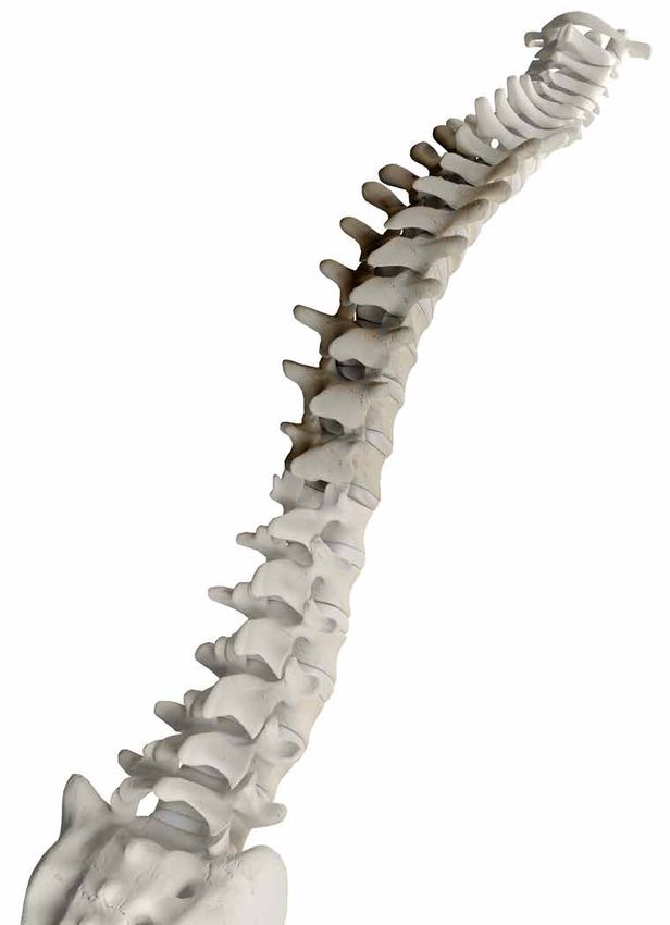
Arsenal Degenerative — Spinal Fixation System

    PREFACE
    Posterior Spinal fusion to treat thoracolumbar                                                              Alphatec strives to move spinal fixation forward and
    pathologies has been performed since the early 1900’s                                                       continues innovation by further enhancing the surgeon and
    and continues to evolve today. The desire for improved                                                      patient surgical experience. The Arsenal™ Degenerative
    patient outcomes and enhanced surgical experience                                                           Spinal Fixation System was thoughtfully designed to
    has continued to drive innovation in this segment of                                                        provide operational efficiency, biomechanical strength, and
    spinal surgery. Today’s spinal fixation systems are more                                                    surgical simplicity while providing a complete solution to
    advanced than ever, and require increased mechanical                                                        combat complex degenerative pathologies.
    advantage, simplified instrumentation, a better anatomical
                                                                                                                The combination of low-profile implants, intuitive
    fit, and the necessary strength to achieve a solid fusion.
                                                                                                                instrumentation, and proven strength are certain to
                                                                                                                quickly become allies.

    CONTENTS
    System Overview -           A   ....................................................................................................................... 3
           Intra-Op Imaging -                1    .............................................................................................................. 6
           Pedicle Preparation -                   2   .......................................................................................................... 7
           Screwdriver and Screw Assembly -                                  3    .................................................................................... 9
           Screw Insertion -             4    .............................................................................................................. 10
           Rod Measurement & Contouring -                                5       .................................................................................... 11
           Rod Insertion -           6   ................................................................................................................. 12
           Rod Reduction -               7       ............................................................................................................. 13
           Parallel Compression -                      8   .................................................................................................... 16
           Parallel Distraction -                 9    ........................................................................................................ 16
           Final Tightening -            10       ............................................................................................................ 17
           Bridge System -           11      ............................................................................................................... 18
           Decortication & Graft Placement -                             12      ................................................................................... 19
           Implant Removal -                 13    ........................................................................................................... 19
           Revision Implants -                   14    ........................................................................................................ 20
           Pelvic Fixation Implants -                      15   ................................................................................................. 21
           Instruments-         16   ................................................................................................................... 21
           Implants -      17   ....................................................................................................................... 26
           Instructions For Use - .......................................................................................................... 31

    The Arsenal Spinal Fixation System is not in any way affiliated with Arsenal Medical.

2                                                                                                                                                                          www.alphatecspine.com
Surgical Technique Guide

A SYSTEM OVERVIEW

  Features

  The Arsenal Spinal Fixation System
  was designed to enhance the surgical
  experience by providing surgeons the
  following:

  •   A comprehensive system capable
      of handling complex degenerative
      pathologies.

  •   Ergonomically designed
      instrumentation
        ``Improved mechanical advantage
          with lighter weight materials
        ``Improved tactile feel
          and comfort

  •   Low-Profile Screws
        ``Minimized implant profile for a
          better anatomical fit.

                                                                       3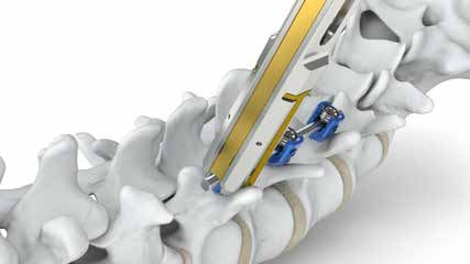
Arsenal Degenerative — Spinal Fixation System

    A •   Dual Lead Threads
            ``Provides faster screw delivery
            ``Reduces OR time
            ``Reduces surgeon fatigue

      •   Color-coded screw shanks
            ``For quick identification of shank
              diameter

      •   76 degrees of variability
            ``To better accommodate varying
              anatomy

                                                  76º   76º

4                                                        www.alphatecspine.com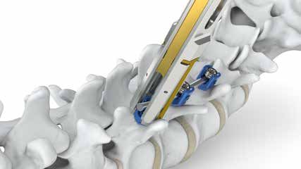
Surgical Technique Guide

A •   Sacral and Reduction Screws
        ``Facilitate long constructs to the
          pelvis
        ``Spondylolisthesis reduction

  •   Revision Connectors
        ``Simplify connection to adjacent
          level constructs
        ``Provide flexibility in complex
          anatomical situations

                                                Optional

             Blue indicates compatibility
             with 5.5mm rod, silver indicates
             compatibility with 6.35mm.

                                                                                      5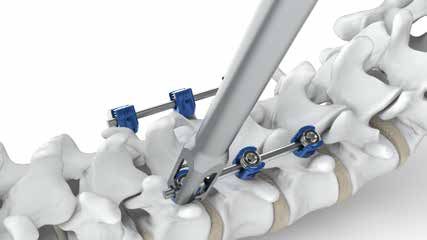
Arsenal Degenerative — Spinal Fixation System

    1 INTRA-OP IMAGING
      •   Prior to preparing the pedicles for
          screw insertion, determine the Sagittal
          and Coronal orientation of the pedicles
          for the vertebrae to be instrumented.
          Utilize a true A/P and lateral radiograph
          or C-Arm image (Figure 1a and 1b).

                                                      Figure 1a - A/P Image showing lumbar        Figure 1b - Lateral Image showing lumbar
                                                      vertebral bodies                            vertebral bodies

      •   Identify the appropriate anatomical
          landmarks to create the entry points
          and pilot holes for screw insertion
          (Figures 2a and 2b).

                                                      Figure 2a - A/P Image showing entry point   Figure 2b - Lateral Image showing entry
                                                      for lumbar probe                            point for lumbar probe

6                                                                                                                www.alphatecspine.com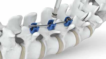
Surgical Technique Guide

2 PEDICLE PREPARATION
  •   Create a pilot hole in the pedicle at the
      junction of the transverse process and
      the superior articular process using a
      high speed burr.

  •   Next, use a pedicle probe to complete
      the cannulation of the pedicle (Figures
      3a & 3b).

                                                  Figure 3a    Figure 3b

  •   Following preparation of the pedicle, a
      Ball Tip Probe can be used to palpate
      the pedicle wall to ensure its integrity.
      (Figures 4a & 4b)

                                                  Figure 4a    Figure 4b

       TIP: The GOLD portion of all
            Arsenal instruments is 30mm
            long for quick reference to
            depth.

                                                                                         7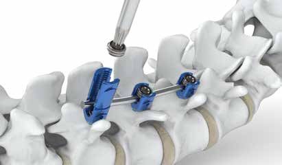
Arsenal Degenerative — Spinal Fixation System

    2 PEDICLE PREPARATION (CONTINUED)
      •   Arsenal Polyaxial Screws have
          self-tapping triple cutting flutes to
          obviate the need for tapping should
          the surgeon so choose. Therefore,
          pedicle screws may be inserted
          immediately following the preparation
          and verification of pedicle wall integrity.
          However, in cases of dense, sclerotic,
          or osteoporotic bone, tapping is
          recommended.

      •   Select the appropriate diameter tap,
          insert it into the pedicle and stop at the
          desire depth. (Figures 5a).
                                                        Figure 5a   Figure 5b

      •   Following final preparation of the
          pedicle, a Ball Tip Probe can again be
          used to follow the tapped threads
          through the cancellous bone and
          palpate for any perforations in the
          pedicle wall or anterior vertebral body
          (Figures 6a & 6b).

                                                        Figure 6a   Figure 6b

8                                                                               www.alphatecspine.com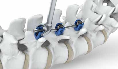
Surgical Technique Guide

3 SCREWDRIVER AND SCREW ASSEMBLY
  •   Assemble the Axial Ratcheting handle
      and the appropriate length pedicle
      screw onto the Locking Polyaxial
      Screwdriver.
        ``STEP 1. Connect the Axial
          Ratcheting Handle onto the
          proximal end of the screwdriver
          and ensure the 1/4” square drive
          of the shaft is fully engaged with     Figure 7
          the handle (Figure 7).
        ``STEP 2. With the screw in the
          caddy, insert the hexalobe end
          of the screwdriver into the screw
          and thread the silver locking collar
          clockwise into the head of the
          screw (Figures 8a, 8b, 8c).
        ``STEP 3. Once the outer sleeve is
          fully tightened, slide the locking
          collar distally into the locked
          position. A green indicator ring       Figure 8a               Figure 8b

          confirms the driver is loaded,
          locked & ready (Figure 9).

  •   The T25 Self Retaining Screwdriver
      may also be used to insert a polyaxial
      pedicle screw.

                                                             Figure 8c

                                                             Figure 9

                                                                                                    9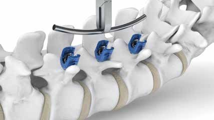
Arsenal Degenerative — Spinal Fixation System

     4 SCREW INSERTION
       •   Once the screwdriver and screw
           assembly is complete, insert the
           screw into the pedicle. Set the Axial
           Ratcheting Handle in the forward
           position and ratchet clockwise until the
           screw has reached the desired depth.

       •   To disengage the screwdriver, slide
           the locking collar proximally to the
           unlocked position and unthread the
           outer shaft from the screw head.
           (Figure 10)                                Figure 10

10                                                                www.alphatecspine.com
Surgical Technique Guide
5 ROD MEASUREMENT & CONTOURING
• Use the Head Positioner to align
polyaxial screws for easier rod insertion
(Figure 11a ). If additional screw depth
adjustment is needed, the T25 Self
Retaining Screwdriver can be used
(Figure 11b).
• With the screws in place, the Rod
Template can be used to determine the
appropriate rod contour and length.
• If required, a Rod Cutter and French
Rod Bender may be used to achieve
the desired rod length and contour.
Figure 11a
Contoured rods cannot be cut
using a Tabletop Rod Cutter.
It is recommended that rods be
bent in one direction only. Over
manipulation and bending may
cause eventual breakage of the
rod.
Figure 11b
TIP: Prior to rod placement,
the operating table can be
adjusted to restore lumbar
lordosis.
11Arsenal Degenerative — Spinal Fixation System
6 ROD INSERTION
• Place the rod using the Multipurpose
Forceps (Figure 12).
Figure 12
• Once the rod is properly in place, load
the set screws from the caddy using
either the Double Ended or T27 Set
Screw Starter (Figure 13). Place the set
screws into the screw heads and rotate
clockwise until provisionally tightened.
Figure 13
TIP: Rotate the set screw
counterclockwise a ¼ turn to
ensure a smooth start every
time.
12 www.alphatecspine.comSurgical Technique Guide
7 ROD REDUCTION
• The Arsenal Spinal Fixation System
provides the surgeon with a variety
of rod reduction options: High Top
Screws, Rod Pusher, Rod Rocker,
Axial Reducer, and Pistol Persuader*.
Depending on the anatomy and the
perceived force required, the surgeon
may utilize any one of these methods
to fully seat the rod into the implant and
allow engagement of the set screw.
• Reduction screws may be utilized to
facilitate a rod reduction of 20mm
in cases with difficult anatomy or if
spondylolisthesis reduction is required. Figure 14
(Figure 14)
• If the rod is slightly proud with respect
to the implant, the Rod Pusher or Rod
Rocker can be used. Slide the Rod
Rocker pins into the lateral chevron
features of the implant and rock the
handle back to make contact with the
rod and leverage it into the implant
(Figure 15a). When the rod is fully
seated, insert the set screw using the
T27 Set Screw Starter (Figure 15b).
The Rod Rocker has
Figure 15a
approximately 9mm of
reduction capability.
The High Top Screws have
20mm of reduction capability.
Figure 15b
* Optional
13Arsenal Degenerative — Spinal Fixation System
7 ROD REDUCTION
• Use the Axial Reducer when additional
force and distance is required to seat
the rod into the screw head.
• With the rod in place, position the
Axial Reducer over the implant and
snap it into place using the “drop
and lock” technique. The reducer
will automatically lock onto the
screw (Figure 16a). Confirm proper
engagement by giving a light tug
upward.
• To reduce the rod, turn the handle of
the Axial Reducer clockwise until the Figure 16a
rod is fully seated into the screw head,
as indicated by the laser mark lines.
If needed, the Hex Drive Adapter with
Ratcheting Handle can be used to
provide additional torque on the Axial
Reducer (Figure 16b).
• Insert a set screw through the cannula
of the Axial Reducer using the T27 Set
Screw Starter and provisionally tighten.
• Remove the Axial Reducer by
squeezing the gold release tabs and
pull up. It is not necessary to unthread
the reducer (Figure 16c).
Figure 16b
The Axial Reducer has
approximately 50mm of
reduction capability.
Figure 16c
14 www.alphatecspine.comSurgical Technique Guide
7 ROD REDUCTION
• The Pistol Persuader* can also be used
to reduce the rod. Position the Pistol
Persuader over the screw and drop it
over the top (Figure 17a). Next squeeze
the handles to lock the Persuader
to the screw. A green indicating line
confirms the Pistol Persuader is locked
to the screw. Confirm connection with a
light tug upward.
• To reduce the rod, repeatedly squeeze
the Ratcheting Handle until the rod is
fully seated into the screw.
• Insert a set screw through the cannula Figure 17a
of the Persuader using the Long T27
Set Screw Starter and provisionally
tighten.
• Remove the Persuader by pressing the
thumb release down (Figure 17b).
The Pistol Persuader has
approximately 30mm of
reduction capability.
Figure 17b
* Optional
15Arsenal Degenerative — Spinal Fixation System
8 PARALLEL COMPRESSION
• Compression can be performed at any
instrumented level to restore sagittal
alignment. To begin, tighten the set
screw on one side of the motion
segment and leave the set screw
loose in the adjacent segment to be
compressed.
• Place the Parallel Compressor tips
outside of the screw heads and over
the rod. Squeeze the handles until
adequate compression is attained.
• Finally, use the T27 Set Screw Starter
to tighten the set screw and maintain
Figure 18
compression (Figure 18).
9 PARALLEL DISTRACTION
• To begin, tighten the set screw on one
side of the motion segment and leave
the adjacent set screw loose. Place
the tips of the Parallel Distractor over
the rod and between the implants, and
then squeeze the handles to distract.
When adequate distraction is attained,
use the T27 Set Screw Driver to tighten
the set screw and maintain distraction
(Figure 19).
Figure 19
16 www.alphatecspine.comSurgical Technique Guide
10 FINAL TIGHTENING
• Final tightening of the construct should
be performed when all screws and rods
are in their final position.
• Connect the Torque Limiting T-Handle
with aqua band to the T27 Set Screw
Driver.
• Insert the torque driver assembly
through the cannula of the Anti-Torque
and engage the tip of the torque driver
into the set screw (Figure 20). Figure 20
• Slide the Anti-Torque down until the
instrument is fully seated over the
rod and implant. Turn the T-Handle
clockwise to tighten. Final tightening
is achieved when the T-Handle audibly
clicks (Figure 21 & 22).
Figure 21
• Alternatively, the Torque Indicating
*
T-Handle can be used for final
tightening. Assemble the T-Handle
to the torque driver and insert the tip
into the set screw. Turn the T-Handle
clockwise, noting the position of
the torque indicating arrows. Final
tightening is achieved when the torque
indicating arrows are aligned (Figure
22a).
Figure 22a
Figure 22
* Optional - must be ordered seperately
17Arsenal Degenerative — Spinal Fixation System
11 BRIDGE SYSTEM
• The Arsenal Variable Bridge implants
can be used to increase the torsional
stability of a construct. Variable Bridges
should be placed at each end of longer
constructs to increase construct
rigidity.
• Use the Bridge Gauge to determine the
proper length of the Variable Bridge.
(Figure 23). Figure 23
• Once the appropriate Variable Bridge
is selected, use the Bridge Inserter to
engage a lateral set screw.
(Figure 24).
• The Bridge Inserter can then be used
to hook and articulate the Variable
Bridge around the rods (Figure 25).
Once precise contact has been
achieved between the bridge and the
rods, the Bridge Inserter can be used
to provisionally tighten the bridge to
the rods.
• To final tighten the Variable Bridge,
connect the Torque Limiting T-Handle Figure 24
with gold band to the T25 Bridge
Driver.
• Insert the driver assembly into a
lateral set screw. Turn the T-Handle
clockwise. Final tightening is achieved
when the T-Handle audibly clicks. Final
tighten both lateral set screws prior to
tightening the center set screw.
• To final tighten the center set screw,
slide the driver assembly into the
Variable Bridge Anti-Torque and place
it over the center set screw. Turn the
T-Handle clockwise. Final tightening is
achieved when the T-Handle audibly
clicks. Figure 25
TIP: Prior to bridge placement,
ensure that the bridge set
screws are backed out to
ensure ease of placement
onto the rod.
18 www.alphatecspine.comSurgical Technique Guide
12 DECORTICATION & GRAFT PLACEMENT
• Use of the Arsenal Spinal Fixation
System requires supplementary bone
graft. When using allograft or autograft
bone to facilitate bony fusion, care
should be taken to place the graft
material directly onto the decorticated
bony surfaces.
• To see Alphatec’s bone graft extension
offering, please see our brochures for
3D Profuse (LIT-83233) products.
13 IMPLANT REMOVAL
• Arsenal Set Screws may be removed
using a T27 screw driver.
• The Pedicle Screws may be removed
using a T25 screw driver.
TIP: Arsenal Polyaxial Screws may
need to be remobilized to
ease driver engagement.
• The Remobilizer may be used to restore
variability to the polyaxial screws. To
restore variability to the Polyaxial Screw
remove the set screw and rod, place
the tip of the Remobilizer in the head
of the screw and squeeze the handle.
Verify Polyaxial Head variability by
rotating the Remobilizer instrument
prior to releasing the handle.
• The Variable Bridge may be removed
with a T25 Screw Driver.
19Arsenal Degenerative — Spinal Fixation System
14 REVISION IMPLANTS
• If revision procedures are required, the
Arsenal Revision module offers Rod
Connectors, Revision Rod Connectors,
and larger diameter screws to help
facilitate revision and adjacent level
procedures.
• Rod Connectors (Figure 26) utilize the Axial Connector
Part # 47008-55-030
Axial Connector*
Part # 47008-65-030
larger T27 set screw for additional
strength when connecting to the rod.
To final tighten the construct, assemble
the Torque Limiting T-Handle with
the T27 Set Screw Torque Shaft and
drive the set screw clockwise until the
T-Handle provides an audible click. No
anti-torque is required. Domino Rod Connector Domino Rod Connector
Part # 47018-55-635
*
Part # 47018-55-055
Rod Connector
Part # 47028-55-055
Rod Connector *
Part # 47028-55-635
Blue indicates compatibility
with 5.5mm rod, silver indicates
compatibility with 6.35mm.
Wide Rod Connector
Part # 47038-55-055
Wide Rod Connector
Part # 47038-55-635
*
Open Side-loading Rod
Connector Part # 47048-55-055
*
Open Side-loading Rod Connector
Part # 47048-55-635
Revision Connector In-line Revision Connector
Part # 47068-55-080 Part # 47089-55-080
* Optional
Figure 26
20 www.alphatecspine.comSurgical Technique Guide
15 PELVIC FIXATION IMPLANTS
• The Arsenal Pelvic Fixation module
facilitates long constructs to the
sacrum and ilium by providing multiple
fixation options for the unique anatomy
of the pelvis. Open Offset Connectors,
Sacral and Polyaxial screws have been
provided to help reduce cantilever and
pull out stresses.
16 INSTRUMENTS
Stopped Awl
Part # 87001
* Straight Ball
Tip Probe
Curved Ball
Tip Probe
Curved Lumbar Probe
Part # 87105-05
Curved Thoracic Probe
Part # 87146-05
Part # 87002 Part # 87003
* Optional
21Arsenal Degenerative — Spinal Fixation System
16 INSTRUMENTS
4.0mm Tap 5.5mm Tap 7.5mm Tap Alphatec Ratcheting
Part # 87107-040 Part # 87107-055 Part # 87107-075 Axial Handle
Part # 86073-1100
4.5mm Tap 6.5mm Tap 8.5mm Tap
Part # 87107-045 Part # 87107-065 Part # 87107-085
Polyaxial Reduction Locking Polyaxial Locking Polyaxial T25 Self Retaining Polyaxial Head
Screwdriver * Polyaxial Reduction Screwdriver Driver Adjuster
Part # 87033 Screwdriver*
Part # 87038
Screwdriver
Part # 87012
Part # 87011 Part # 87013 Part # 87014
* Optional
22 www.alphatecspine.comSurgical Technique Guide
16 INSTRUMENTS
Double Sided Set T27 Set Screw Torque Limiting Torque Indicating Alphatec Ratcheting Anti Torque
Part # 87030
*
Screw Inserter Driver
Part # 87034
T-Handle (Aqua Band)
Part # 86013-1200-080
*
T-Handle
Part # 86903-0600-080
T-Handle
Part # 86013-1100
Part # 87031
*
Part # 86013-1200-090
French Rod Bender Multipurpose Axial Reducer Axial Reducer 25mm Hex Adaptor
Part # 87016 Forceps Part # 87066 Anti Torque Adaptor Part # 87065
Part # 87024 Part # 87064-13
* Optional
23Arsenal Degenerative — Spinal Fixation System
16 INSTRUMENTS
Rod Rocker Rod Pusher T27 Set Screw Compressor (Parallel) Distractor (Parallel)
Part # 87020 Part # 87022 Inserter Part # 87026 Part # 87027
Part # 87029
Rod Template Polyaxial Remobilizer *
Pistol Persuader Rod Gripper* Polyaxial Provisional
130mm
Part # 87015-130
Part # 87036 Part # 87019-11 Part # 87018 Locking Tool
Part # 87035
*
* Optional
24 www.alphatecspine.comSurgical Technique Guide
16 INSTRUMENTS
*
In situ Rod *
In situ Rod Long T27 Set Bridge Anti Torque
Bender Left
Part # 87060
Bender Right
Part # 87061 Part # 87044
*
Screw Inserter Part # 87048
T25 Bridge Inserter
Part # 87063
T25 Bridge Driver
Part # 87039
Bridge Gauge
Part # 87040
Bridge Caliper
Part # 87041
* Torque Limiting T-Handle
(Gold Band)
Part # 86012-1500-040
* Optional
25Arsenal Degenerative — Spinal Fixation System
17 IMPLANTS
Set Screw
Part # 47127
Polyaxial Screw Polyaxial Screw Polyaxial Screw Polyaxial Screw
Part # 47000-040-XXX Part # 47000-055-XXX Part # 47000-065-XXX Part # 47000-075-XXX
Polyaxial Screw Polyaxial Screw Polyaxial Screw Polyaxial Screw
Part # 47000-045-XXX Part # 47000-085-XXX Part # 47000-095-XXX Part # 47000-105-XXX
Polyaxial Screw
Part # 47000-XXX-XXX
Open Offset Connector
Sacral Screw Reduction Screw
Part # 47008-XXX
Part # 47100-XXX-XXX Part # 47200-XXX-XXX
Pre-contoured Rod
Part # 47003-55-XXX
Straight Rod Variable Bridge
Part # 48001-055-XXX Part # 47006-XX
XX
XX
XX
XX
XX
26 www.alphatecspine.comSurgical Technique Guide
ARSENAL™ SPINAL FIXATION SYSTEM
GENERAL INFORMATION:
The Arsenal Spinal Fixation System is intended for posterior, non-cervical, spinal fixation as an In addition, the removed implant has not been designed or validated for the decontamination of
adjunct to fusion for the treatment of degenerative disease, deformity, and trauma indications. microorganisms. Reuse of this product could lead to cross-infection and/or material degradation as
The Arsenal System consists of a variety of shapes and sizes of rods, screws, hooks, a result of the decontamination process.
connectors, and bridges that provide temporary internal fixation and stabilization during bone 6. The instruments in the Arsenal System are reusable surgical devices except for the Single-Use CBx
graft healing and/or fusion mass development. The screws, hooks, connectors, and bridges Pedicle Marker Taps and the guide wires used with the Arsenal System, which are single use only.
are manufactured from surgical grade titanium alloy (Ti-6Al-4V ELI). The rods are available in Single use instruments are disposable devices, designed for single use and should not be re-used
commercially pure titanium, titanium alloy, and cobalt chrome (CP Ti Grade 4, Ti-6Al-4V ELI, or re-processed. Reprocessing of Single Use Instruments may lead to instrument damage and
and Co-28Cr-6Mo). possible improper function.
7. Do not comingle titanium and stainless steel components within the same construct.
The Arsenal System may be used in connection with Alphatec Spine’s Solanas® Posterior 8. The final operative procedure with the system must include tightening of the set screws in order
System, which in turn connects with Avalon® Occipital Plate System creating additional levels to maintain construct integrity. Each locking mechanism must be rechecked for tightness before
of fixation. The Variable Bridges are appropriate for use with other Alphatec Spine 5.5 rod-based closing the soft tissues as noted in the Intraoperative Management section.
systems, which include both the Zodiac® Spinal Fixation System and the Xenon® Pedicle 9. The safety and effectiveness of pedicle screw spinal systems have been established only for spinal
Screw System. conditions with significant mechanical instability or deformity requiring fusion with instrumentation.
These conditions are significant mechanical instability or deformity of the thoracic, lumbar, and sacral
INDICATIONS FOR USE, DEGENERATIVE: spine secondary to severe spondylolisthesis (grades 3 and 4) of the L5-S1 vertebra, degenerative
The Arsenal Spinal Fixation System is intended for posterior, non-cervical fixation in skeletally spondylolisthesis with objective evidence of neurological impairment, fracture, dislocation, scoliosis,
mature patients as an adjunct to fusion for the following indications: degenerative disc disease kyphosis, spinal tumor, and failed previous fusion (pseudarthrosis). The safety and effectiveness of
(defined as back pain of discogenic origin with degeneration of the disc confirmed by history these devices for any other conditions are unknown.
and radiographic studies); spondylolisthesis; trauma (i.e. Fracture or dislocation); spinal 10. Based on the fatigue test results, the physician/surgeon should consider the levels of implantation,
stenosis; curvatures (i.e., scoliosis, kyphosis and/or lordosis); tumor; pseudarthrosis; and/or patient weight, patient activity level and patient conditions, which may impact the performance of
failed previous fusion. the system when using this device. Use of these systems is significantly affected by the surgeon’s
proper patient selection, preoperative planning, proper surgical technique, proper selection and
When used for posterior non-cervical screw fixation in pediatric patients, the Arsenal Spinal placement of implants.
Fixation System implants are indicated as an adjunct to fusion to treat adolescent idiopathic 11. Risks identified with the use of these devices, which may require additional surgery, include device
scoliosis. Additionally, the Arsenal Spinal Fixation System is intended to treat pediatric patients component failure, loss of fixation/stabilization, non-union, vertebral fracture, neurological injury,
diagnosed with the following conditions: spondylolistheis/spondylolysis, and fracture caused by vascular or visceral injury.
tumor and/or trauma. Pediatric pedicle screw fixation is limited to a posterior approach. 12. Risk factors that may affect successful surgical outcomes include: Alcohol abuse, obesity, patients
with poor bone, muscle and/or nerve quality. Patients who use tobacco or nicotine products should
The Arsenal Spinal Fixation System is intended to be used with autograft and/or allograft. be advised of the consequences that an increased incidence of non-union has been reported with
patients who use tobacco or nicotine products.
INDICATIONS FOR USE, DEFORMITY: 13. The benefit of spinal fusions utilizing any pedicle screw fixation system has not been adequately
The Arsenal Spinal Fixation System is intended for posterior, non-cervical fixation in skeletally established in patients with stable spines. Without solid bone fusion, these devices cannot be
mature patients as an adjunct to fusion for the following indications: degenerative disc disease expected to support the spine indefinitely and may fail due to bone-metal interface, rod failure or
(defined as back pain of discogenic origin with degeneration of the disc confirmed by history bone failure.
and radiographic studies); spondylolisthesis; trauma (i.e. Fracture or dislocation); spinal 14. It is critical that set screws are turned to the proper torque values as recommended in the Surgical
stenosis; curvatures (i.e., scoliosis, kyphosis and/or lordosis); tumor; pseudarthrosis; and/or Technique Guides, using the instruments provided. Failure to tighten the set screws to the
failed previous fusion. recommended torque value could compromise the mechanical stability of the connector.
15. The implants and instruments of Alphatec Spine product lines should not be used with any other
When used for posterior non-cervical pedicle screw fixation in pediatric patients, the Arsenal company’s spinal systems.
Spinal Fixation System implants are indicated as an adjunct to fusion to treat progressive spinal 16. To prevent guide wire breakage, do not use a kinked or bent guide wire.
deformities (i.e., scoliosis, kyphosis, or lordosis) including idiopathic scoliosis, neuromuscular 17. Guide wire advancement should be monitored using fluoroscopic imaging. Failure to do so may
scoliosis, and congenital scoliosis. Additionally, the Arsenal Spinal Fixation System is intended cause the guide wire or part of it to advance through the bone and into a location that may cause
to treat pediatric patients diagnosed with the following conditions: spondylolisthesis / damage to underlying structures.
spondylolysis, fracture caused by tumor and/or trauma, pseudarthrosis, and/or failed previous
fusion. Pediatric pedicle screw fixation is limited to a posterior approach. PRECAUTIONS:
1. The implantation of pedicle screw spinal systems should be performed only by experienced
The Arsenal Spinal Fixation System is intended to be used with autograft and/or allograft. spinal surgeons with specific training in the use of this pedicle screw spinal system because
this is a technically demanding procedure presenting a risk of serious injury to the patient.
CONTRAINDICATIONS: 2. The Arsenal System has not been evaluated for safety and compatibility in the Magnetic
The system is contraindicated for: Resonance (MR) environment. The system has not been tested for heating or migration in
1. Use in the cervical spine. the MR environment.
2. Use with bone cement. 3. Device components should be received and accepted only in packages that have not been
3. Patients with allergy to Titanium or Cobalt Chrome. damaged. Damaged implants and damaged or worn instruments should not be used.
4. Patients with osteopenia, bone absorption, bone and/or joint disease, deficient soft tissue Components must be carefully handled and stored in a manner that prevents scratches,
at the wound site or probable metal and/or coating intolerance. damage, and corrosion.
5. Patients with infection, inflammation, fever, tumors, elevated white blood count, obesity, 4. The physician/surgeon should consider the levels of implantation, patient weight, patient
pregnancy, mental illness and other medical conditions, which would prohibit beneficial activity level, other patient conditions, etc. which may have an impact on the performance
surgical outcome. of the system.
6. Patients resistant to following post-operative restrictions on movement especially in athletic
and occupational activities. POSSIBLE ADVERSE EFFECTS:
7. Spinal surgery cases that do not require bone grafting and/or spinal fusion. The following complications and adverse reactions have been shown to occur with the use
8. Reuse or multiple uses. of similar spinal instrumentation. These effects and any other known by the surgeon must be
discussed with the patient preoperatively.
WARNINGS: 1. Initial or delayed loosening, disassembly, bending, dislocation and/or breakage of device
1. The implants and instruments of the system are provided non-sterile. Refer to the CLEANING and components.
STERILIZATION sections. 2. Physiological reaction to implant devices due to foreign body intolerance including
2. The safety and effectiveness of this device has not been established for use as part of a growing rod inflammation, local tissue reaction, seroma, and possible tumor formation.
construct. This device is only intended to be used when definitive fusion is being performed at all 3. In the case of insufficient soft tissue at and around the wound site to cover devices, skin
instrumented levels. impingement and possible protrusion through the skin may occur.
3. The system implants are used only to provide temporary internal fixation during the bone fusion 4. Loss of desired spinal curvature, spinal correction and/or a gain or loss in height.
process with the assistance of a bone graft. A successful result may not be achieved in every 5. Infection and/or hemorrhaging.
instance of use with these devices. Without solid bone fusion, these devices cannot be expected to 6. Bone graft, vertebral body and/or sacral fracture, and/or discontinued growth of fused bone
support the spine indefinitely and may fail due to bone-metal interface, rod failure or bone failure. at, above and/or below the surgery level.
4. The implants are designed and intended as temporary fixation devices. The devices should be 7. Non-union and/or pseudarthrosis.
removed after complete healing has occurred. Devices which are not removed after serving their 8. Neurological disorder, pain and/or abnormal sensations.
intended purpose may bend, dislocate, or break and/or cause corrosion, localized tissue reaction, 9. Revision surgery.
pain, infection, and/or bone loss due to stress shielding. Complete postoperative management to 10. Death.
maintain the desired result should also follow implant removal surgery.
5. The product implants are single use devices. Do not reuse. While an implant may appear Excerpt from INS-076E
undamaged, it may have small defects or internal stress patterns that could lead to fatigue failure.
The Arsenal Spinal Fixation System is not in any way affiliated with Arsenal Medical.
27Arsenal Degenerative — Spinal Fixation System
CORPORATE HEADQUARTERS CUSTOMER SERVICE Arsenal is a trademark and the
Alphatec Spine logo is a registered
5818 El Camino Real Toll Free: 800.922.1356 trademark of Alphatec Spine, Inc.
Carlsbad, California 92008 Local: 760.431.9286 © 2016 Alphatec Spine, Inc. All rights
reserved.
Fax: 800.431.1624
LIT-84451D | 2016/11/03You can also read