SFSA CAST IN STEEL 2021 COMPETITON
←
→
Page content transcription
If your browser does not render page correctly, please read the page content below
UNIVERSITY: INSTITUTO
TECNOLÓGICO DE SALTILLO SFSA CAST IN STEEL 2021
COMPETITON
TECHNICAL REPORT OF
“THOR’S HAMMER”
SPONSOR: JOSE ANTONIO
LAZCANO FERNANDEZ (SEMSA
FOUNDRY)
ADVICED BY: DR. EFRAÍN
ALMANZA CASAS
VALHALLA DONKEYS TEAM:
ARANZAZÚ PINEDA
SILVIA RAMOS
JORGE ARELLANO
MARIO GARCIA
JOSÉ SÁNCHEZ
MARCH 2021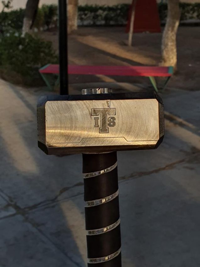
TABLE OF CONTENTS

TEAM MEMBERS ........................................................................................................................... 2
ABSTRACT...................................................................................................................................... 3
INTRODUCTION ............................................................................................................................. 4
HISTORICAL BACKGROUND ........................................................................................................... 5
HAMMER DESIGN .......................................................................................................................... 6
MODEL MANUFACTURE ................................................................................................................ 7
ALLOY SELECTION .......................................................................................................................... 8
CASTING APROACH ....................................................................................................................... 9
SIMULATION ............................................................................................................................... 11
MOULDING PROCESS................................................................................................................... 12
MELTING AND POURING PROCESS .............................................................................................. 13
MACHINING PROCESS AND FINAL DETAILS ................................................................................. 14
MICROSTRUCTURAL ANALYSIS AND HARDNESS TEST ................................................................. 15
THOR’S HAMMER RESULT ........................................................................................................... 17
ACKNOWLEDGMENTS AND CONCLUSIONS ................................................................................. 18
REFERENCES ................................................................................................................................ 18

TEAM MEMBERS

 José Raúl Sánchez Arredondo                   Silvia Guadalupe Ramos Sánchez                        Aranzazú Pineda Arias
Instituto Tecnológico De Saltillo              Instituto Tecnológico De Saltillo               Instituto Tecnológico De Saltillo
 Materials Engineering Degree                    Materials Engineering Degree                   Materials Engineering Degree

                     Mario Alberto García Reyna                          Jorge Alejandro Arellano De Hoyos
                   Instituto Tecnológico De Saltillo                       Instituto Tecnológico De Saltillo
                    Materials Engineering Degree                            Materials Engineering Degree
ABSTRACT

This document was prepared to be able to document the process that was carried out in the
realization of Thor's hammer in this competition, considering the theoretical and practical
knowledge that we have acquired throughout the career we are currently studying. as well
as the historical background to in this way be able to propose an optimal design which,
combined with the skills, allowed us to develop an efficient hammer with all the
characteristics and more importantly, that it fulfills its function as well as being aesthetically
pleasing.

The document describes from the design and simulation of the casting process, going
through the melting and casting process until reaching the results that allowed us to present
information about the properties that we present on a microstructural analysis.

In the same way, the subsequent manufacturing processes are mentioned, such as the
engraved , machining and the addition of the leather in the hammer handle, as well as the
information of the alloy from which it was made, also in this document it is highlighted the
participation of the people involved in the project as well as the consultants who helped us
make this possible.

Key Words: Metal casting; Thor’s Hammer; Project; Casting; Melting and pouring; Design
Process; Alloy.

INTRODUCTION

In the present project organized by the Steel Founders’ Society of America (SFSA) for the Cast
in Steel 2021 competition, the manufacturing process was developed from the design of a
model of Thor´s Hammer following the establishes specifications. Thor’s Hammer must be
20 inches maximum and 6 pounds maximum weight and be as close to the original model as
possible.

The steel has been present in our lives for a long time and has brought with it important
technological, scientific, and economical advances, so this metal, as well as its alloys, are the
most used in the foundry industry.

The development of the project that is presented below, gave us the opportunity to prove
the skills and knowledge that as students we have acquired throughout our university, from
the design of the model, the selection of the alloy, the molding techniques and casting
systems and everything involved in the casting process to obtain a hammer with the best
properties that fulfill its function.
HISTORICAL BACKGROUND

Thor is a god associated with thunder, storms, and strength, he is the
Asgard protector and the hammer was his weapon called "Mjolnir", it
was not an ordinary weapon, whenever Thor use it with an enemy it
returned to his hands like a boomerang. The hammer was used in
formal ceremonies like births, funerals, and marriages to give his
blessing.

Historian Hilda Roderick Davidson provides an excellent explication of
the hammer.

   "It would seem indeed as though the power of the thunder god,
                                                                 Figure 1. The hammer is made of a
 symbolized by his hammer, extended over all that had to do with the
                                                                 very rare material called Uru. The
                    well-being of the community."                handle is covered with a leather
                                                                 which ensures that it is
Mjolnir is mentioned as a club, an ax, and a hammer. It had many unbreakable.
magical characteristics, such as being able to hit as hard as Thor
wanted, from a light touch to a terrible blow that would destroy mountains. It was also said
that thunder and lightning were the result of the hammer blow and that the hammer had
the ability to shrink enough to be stored in a tunic and then enlarge to be used in combat.

Stones found in Denmark and southern Sweden bear the inscription of a hammer to invoke
divine protection. Sometimes accompanying the engraving of the hammer are inscriptions
where they ask Thor's help to and protection. For example, A Viking stone in Denmark has
the inscription, "May Thor sanctify this tomb."

A precedent for these Thor's hammers used as amulets in the Viking era was recorded during
the period of the great migrations, among the Germans, who took the Thor's amulets as
symbols of strength.

Similar symbols have been found in the Alpine area of northern Italy, where this symbol was
engraved on the lintel of the main door. Its object was the protection of the home.

The use of the Mjolnir has not disappeared despite the Christian presence in Nordic lands for
more than a thousand years, however the Scandinavian sailors continue to carry a Mjolnir as
protection against the dangers of the sea.

The hammer is surrounded by the 24 runes of the Futhark alphabet. and even in the movies
the inscription " who wields this hammer, if it's worthy of it, will possess the power of Thor"
has become popular thanks to american movies.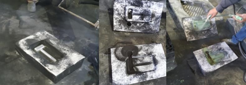
HAMMER DESIGN

Although there are a lot of types of graphic designs of Thor's hammer, we decided to make
the popular culture design featured in the movies and this is because it is a very ergonomic
and stylish design.

We paid a lot of attention to the design because it is one of the most important step of the
process, this is because if there is a defect in it, this defect will be found in the model, the
mold and the final piece if it is not detected in time, also the selection of the software is
very important since it is necessary to take into account the necessary characteristics when
designing the part and avoid future complications.

The design was made considering in the final form that we would have a partition line and if
it would be necessary to consider the exit angles so that the piece was easy to remove,
reaching the conclusion that they would not be necessary due to its geometry.

First, the sketch was made by hand to be able to specify the measures according to the
weight by the call considering the density of the established material, it was designed initially
using AutoCAD software but this design was reviewed by our adviser and we had the need
to resize it, once this was done, we made the decision to change it to a SolidWorks design in
order to refine details and also because this is the format we used to simulate the casting in
Magma Soft

          Figure 2. Initial AutoCAD design                  Figure 3. Final 3D view

The SolidWorks Design helps us to calculate the correct measures and calculate more
accurately the volume of the hammer. In the 2nd figure we present our previous designs and,
in the 3rd , and 4th we present the final design.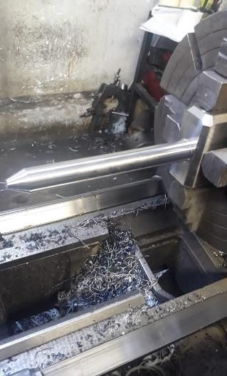
Figure 4. Detailed drawing of the final SolidWorks design

MODEL MANUFACTURE

Once we finished our design, we proceeded to the manufacture of the model which was
made of wood, it was worked in two sections, the head, and the handle.

For the elaboration of the head, the wood was cut in a rectangular shape and the
measurements were marked on it with a small surplus so that when we started the sanding
process the measurements were not affected, after cutting the section that we marked to
give the angular shape of the corners the circle was drilled in the upper part of the head to
be able to fit the handle.

For the elaboration of the handle, a piece of wood was taken which was carefully worked on
a wood lathe with due dimensional control, once it was ready, it proceeded to fit it to the
head of the hammer and it was glued with industrial wood adhesive, once this was done,
measures were taken again to ensure their control.
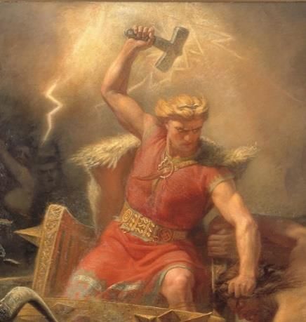
Figure 5. Final Wood model                    Figure 6-7. Model manufacture process

ALLOY SELECTION

The selection of the alloy was based on the previous research we carried out to give us an
idea of what type of steel would be feasible to use, which is why we decided that AISI grade
S steel would be a good option.

After we made the selection, we proceeded to speak with our external advisor to see how
feasible it would be to use it. Thanks to the support provided, we were able to get the
material from the foundry that supported us.

AISI S7 steel is a tool grade steel with high toughness and shock resistant. This has been used
for many years due to its good properties. It reaches 58/60 HRC hardness and can be air-
cooled exhibiting minimal distortion when tempered, offers high compressive strength,
maintains good toughness and is very versatile for cold and warm work applications and is
easy machined in the annealed state, this being approximately 75%.

Within its typical applications we can find that it is applied in tools for chisels, dies and
punches as well as blades for cutting scrap metal.

is composed on average (%) by:

                                 Figure 8. chemical composition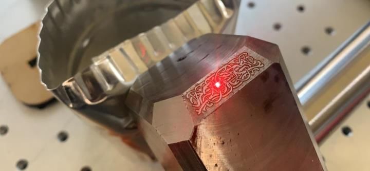
Among its physical properties it should be noted that it has a modulus of elasticity of 207
GPa, a density of 7830 kg / m3 and a thermal conductivity of 28.5 W / m ° K.

When we are talking about material properties, its mechanical behavior should not be
excluded, the tempering temperature is 955 ° c (1750 ° F) and its impact resistance is 169 J,
these last values were obtained from a Charpy notch impact test C.

SISA S7 steel can be nitrided coated with titanium, hard chromium, or nickel coating,
however it is not usually nitrided since the heat treatment carried out before nitriding
generates lower hardness than normal.

CASTING APROACH

First, we consider 2 different options, the first one was investment casting and the second
one was sand casting.

As we know Investment casting is an industrial process based on lost-wax casting, beeswax
was used to form patterns necessary for the casting process. Today, more advanced waxes,
refractory materials and specialist alloys are typically used for making patterns.

The following steps describe the indirect process, which can take two to seven days to
complete.

   1. Produce a master pattern.
   2. Create a mold.
   3. Produce wax patterns.
   4. Assemble wax patterns.
   5. Apply investment materials.
   6. Dewax
   7. Burnout preheating
   8. Pouring
   9. Divesting
   10. Finishing

We consider the disadvantages, for example the main disadvantage was the overall cost,
especially for short-run productions, also the fact that investment casting requires longer
production cycles compared to sand casting, so we proceed to consider our 2nd option, and
this was the one that we choose.
The Sand casting is the most widely used casting process, the steps in the process can be
resumed in 6 steps.

   1.   Mold making
   2.   Clamping
   3.   Pouring
   4.   Cooling
   5.   Removal
   6.   Trimming

We consider all the disadvantages too, for example the possible porosity, but we choose this
casting process because we can work with a lot of variety of materials and the low tooling
and equipment cost, also we know that if we work carefully, we can have the result we were
expecting for.

After deciding which method to use we start to work in the casting design for the molten
steel to pour into the mold.

We use again the SolidWorks software, we stablished the measures for the pouring cup, the
sprue, the runner, and the gate.

We decide to use a circular pouring cup and a circular runner, this due to the design of our
hammer, our first concern was about the circular runner because we thought that this could
cause a turbulent flow, this was the main reason that we decide to create a simulation on
Magma Soft.

                              Figure 9. Pouring cup and runner design
SIMULATION
The simulation was made in the Magma Software (version 5.4.1) with our university
computer laboratory help. Using the magma software, we selected the parameters as green
sand casting, manganese steel (ASTM 128 Grade C), the pouring section at the top of the
riser/feeder, the initial temperature of casting was 1600°C and the pouring temperature
1500°C.
Figure 10.
Casting CAD design in Magma.
Finally, when the all the parameters were selected, we proceed to start the simulation of the
pouring process. It shows us how does the liquid melt will be entering and solidifying inside
of the mold (figure 10 a). At the end of the process, another interest to see was the possible
defects that the hammer would have at the real practice with those conditions. The defects,
as porosity, are shown at the top of the feeder/riser in figure 10 b.
A)B)
Figure 10.
a) Pouring simulation, and b) Porosity section by Magma Software version 5.4.1.
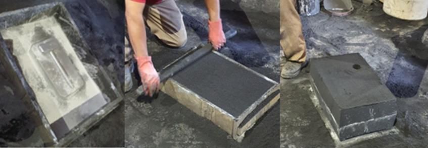
MOULDING PROCESS
Once the model was ready, we contacted our external advisor to establish a date to proceed
with the molding.
As the wooden model was not cut by the established partition line, the elaboration of
wooden model plates was considered to make more easily mold the cope and drag part
without having to cut the original model, after it the plate was made, we proceeded to start
the process, this begins by placing the plate and sprinkling it inside with a release agent, after
adding the sand into the molding box to compact it.
followed by this, the box was carefully turned over and the plate was extracted leaving the
impression of the model, to make the cope box, the model was placed in the cavity and then
the sand was added and compacted, once this was completed the boxes were separated and
the model was removed, then the casting system was made to finish by adding a layer of
paint for molds in green which prevents the metal from penetrating into the sand, in addition
to giving it a good surface.Figure 11 .
Molding Process
MELTING AND POURING PROCESS
At this stage, the induction furnace was preheated 2 hours before the pouring and reaching
approximately 1530°C at the time a chemical composition was made for further
modifications, also the casting ladle was preheated to avoid a thermal shock. Getting the
right composition then the pouring process get started. First, the company proceed to feed
their production and finally our hammer with 5 second of pouring time (shown in figure 12).
The process started with a load of:
C= 1.18% Si= 1.50% Mn= 13.10%
Cr= 2.13% P= 0.09% S= 0.62% Fe= 81.68%
in an induction furnace which fed the previously heated casting pot to proceed to casting
into the sand mold, and pouring temperature was 1475 °C.
Figure 12. Melting process.MACHINING PROCESS AND FINAL DETAILS
After the hammer was removed from the mold, the casting system was cut to give it a quick
subsequent cleaning to remove the remains of sand. This was followed by a machining
process (with milling and lathering machines) to obtain a better surface finish.
Figure 13. Hammer after being cut and cleaned. Figure 14. Milling and Lathering process
At the end of the process, we notice that the clamping jaws had been marked and in the
same way the presence of recovers came to light, but for reasons of time and other situations
beyond our control we did not have the opportunity to repeat the melting and pouring
process.
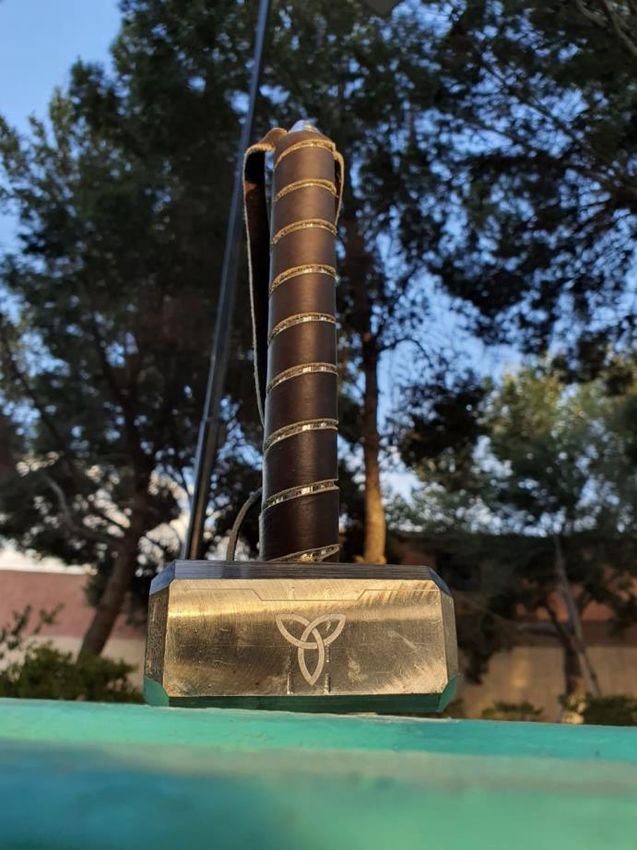
As final details, a laser engraving of the runes present in the design of the hammer was given
on the edges as well as the logo of our educational institution, later a spiral shape coating
with a leather was added on the handle of the hammer so that it would stick more to design.
Figure 15. Final Details.MICROSTRUCTURAL ANALYSIS AND HARDNESS TEST MATERIALS • ASTM A128 Steel specimen • Cutter • 80-2000 abrasive sandpaper • Thick cloth • Thin cloth • Alumina 1, .3, .05 • Liquid alumina 1, .3, .05 • Microscope SECTIONING PROCESS First, we choose the right sample to cut. The specimen was sectioned by the cutter machine that was in the laboratory. The first thing that was done was to adjust the specimen with tweezers until it was fixed in the support to prevent it from moving, Afterwards, the cut was carried out by closing the cutter cover to prevent sparks or a piece of material from flying out when the abrasive disc contacted the piece always taking care of the speed to avoid any failure or damage cause because of it. GRINDING This stage of the procedure was carried out with abrasive meshes on a two-disc automatic Semi grinding machine, starting with the 80 mesh by applying adequate pressure on the disc while it had to be wet with water. The revolutions that were used were from 400 to 450. When we finished with the first mesh, we passed to a higher one, considering that all the lines the sample had were directed to one specific side. At this stage there were no difficulties to conclude with an adequate surface, there were no alterations in the sample. POLISHING This was done to eliminate the fine scratches that were left after grinding the piece looking for a mirror effect. The method that we used was manually and we used a green cloth and powdered alumina, creating a mixture with water. the way the polishing was done was by making small circles with the sample on the paste with a uniform force, also another movement could be the shape of eights for a more efficient polishing.
Figure 16. Mechanical Grinder   Figure 17. Mechanical cutter with   Figure 18. Sample
                                              abrasive disc.               Preparation

For the hardness we use an indentation hardness test that we performed
at our university lab, first we check that the hardness taster was
calibrated, we did this using the patterns. The scale we used was HRC
with a load of KgF with a 1/16 ball indenter.

We took 4 measures.

1.- 53.9

2.- 54.5

3.- 54.6

4.- 53.4

these 4 measures gave us an average of 54.1 HRC, it means 543 HBN.             Figure 19. Hardness Tester

RESULTS
We obtain the results of micrographs in different magnifications. In figure 19, at 10x it shows
austenitic grains with the presence of second phase compounds that must be dissolved in
the austenitic matrix in the solubilizing heat treatment to obtain a homogeneous structure.
In figure 20 at 10x, it shows the microstructural behavior of the austenitic manganese steel,
because of the elevated temperatures of the treatment produced some decarburization
surface in low percentage. Also being etched (figure 20 and figure 21 at 100x) it shows
presence of the second phase compounds (showed as black areas) at the grain boundaries
(showed in the bright area in figure 21) such as Cr7C3, Fe3C and (FeMn4)xC, they are in a very
low proportion so cannot affect that much on the mechanical properties. Obtaining good
resistance in the hammer when doing destructive tests, and also a good percentage of Brinell
Hardness in 543 HBN.
Figure 20. Micrography, without etching Figure 22. Micrography, etching
Figure 21. Micrography, etching 10X
10X 100X
THOR’S HAMMER RESULTACKNOWLEDGMENTS AND CONCLUSIONS
When we accept this challenge instead of thinking about it as a competition, we saw the
opportunity to live this experience as a learning experience not only in terms of knowledge,
but also in the teamwork that we have been developing in the last months to be directly
involved in the foundry industry.
Thanks to this challenge, we have been able to test the knowledge we have acquired
throughout our career as well as the development of new skills that allow us to grow
personally and professionally, helping our training as future engineers.
In the past months we have worked on the process of Thor's hammer from the creative part
of the design to the manufacturing and the result of it, having the opportunity to take
advantage of the skills that each team member offers to fulfill the established objectives of
the Project.
Also, we want to offer especial thanks to the engineers Ing. José Antonio Lazcano, Ing.
Roberto Arredondo, Ing. Karina Diaz, Mr. Manuel, Mr. Samuel, and all the group team inside
of SEMSA foundry for helping us and show us the way of how the stages of the process will
take part to have a final casting piece with the required characteristics of this steel. We are
very thankful also for having the doors open to use their installations and for always having
a great attitude to help!
To our internal advisor Dr. Efraín Almanza for give us the support and provide us all the tools
we needed to make possible this project.
REFERENCES
[1] Higuera, O., Monsalvaje, M., & Gonzales, H., september 2018, “Cooling Kinetics Effect on
Abrasive Wear Behaviour of an ASTM A128 Steel”, Contemporary Engineering Sciences,
ResearchGate.
[2] Servicio Industrial SISA, S.A. de C.V.2018,Acero para golpe y choque.You can also read