SOLARROOF CHEMSET ANCHOR STUD - CODE-COMPLIANT PLANNING AND INSTALLATION GUIDE V1.0 COMPLYING WITH AS/NZS1170.2-2011 AMDT 2-2016 - CLENERGY
←
→
Page content transcription
If your browser does not render page correctly, please read the page content below
SolarRoof™ ChemSet™ Anchor Stud
Code-Compliant Planning and Installation Guide V1.0
Complying with AS/NZS1170.2-2011 AMDT 2-2016
Contents

    1. Introduction                                                             01
    2. Planning                                                                 02
    2.1 Determine Concrete Compressive Strength                                 02
    2.2 Determine Anchor Stud Specifications                                    02
    2.3 Determine the Wind Region of your Installation Site                     02
    2.4 Determine the Terrain Category                                          03
    2.5 Verify Atmospheric Corrosivity Zone of Installation Site                03
    2.6 Determine the Installation Height, Installation Area and                04
         Maximum Interface Spacing
    2.7 Verify Maximum Rail End Overhang                                        04
    2.8 Acquire PV Modules Clamping Zone Information                            04
    3. Tools and Components                                                     05
    3.1 Tools                                                                   05
    3.2 Components                                                              05
    4. System Overview                                                          07
    4.1 Overview of PV-ezRack SolarRoof on Concrete Roofs                       07
    4.2 Precautions during Stainless Steel Fastener Installation                09
    4.2.1 General installation instructions:                                    09
    4.2.2 Safe Torques                                                          09
    5. Installation Instruction                                                 10
    5.1 ChemSet™ Anchor Stud Installation                                       11
    5.2 Tin Interface Installation                                              12
    5.3 Tilt Legs Installation                                                  12
    5.4 Rail Installation                                                       13
    5.5 ComT Installation                                                       14
    6. Certification Letter and Interface Spacing Table                         16
    7. Warranty                                                                 18

Installation Guide_ PV-ezRack SolarRoof ChemSet Anchor Stud V1.0 (March 2021)

    Unit 1, 10 Duerdin St, Clayton VIC 3168, Australia
    Tel: +61 3 9239 8088 Fax: +61 3 9239 8024
    E-mail: tech@clenergy.com.au www.clenergy.com.au
Introduction

1. Introduction

ChemSet™ Anchor Studs are made from                                             •Recycling: Recycle: according to the local relative
quality Grade 5.8 carbon steel to get the most                                  statute.
out of adhesive tensile capacities and meets
Australian Standards. Assembly with Clenergy                                    •Removal: Reverse installation process.
Tin Interfaces and Tilt Legs, PV-ezRack®
SolarRoof™ ChemSet™ Anchor Stud offers                                          •Ensure that there are no less than two professionals
easy and fast PV installation on concrete roofs.                                working on panel installation.

Please review this manual thoroughly before                                     •Ensure the installation of related electrical
installing PV-ezRack® SolarRoof™ ChemSet™                                       equipment is performed by licenced electricians.
Anchor Stud. This manual provides:
                                                                                •Ensuring safe installation of all electrical aspects
1) Supporting documentation for building                                        of the PV array. This includes adequate earth
permit applications relating to PV-ezRack®                                      bonding of the PV array and PV-ezRack® SolarRoof™
SolarRoof™ ChemSet™ Anchor Stud Universal                                       components as required in AS/NZS 5033-2014
PV Module Mounting System,                                                      AMDT 2 2-2018.

2) Planning and installation instructions.                                      • Ensuring that the roof can support the array under
                                                                                  building live load conditions.
Health and Safety regulations. Please also pay
attention to any other relevant State or Federal                                • Ensuring that screws to fix interfaces have
regulations. Please check that you are using                                      adequate pull-out strength and shear capacities as
the latest version of the Installation Manual,                                    installed.
which you can obtain by contacting Clenergy
Australia via email on tech@clenergy.com.au                                     • Maintaining the waterproof integrity of the roof,
or contacting your local distributor in Australia.                                including selection of appropriate flashing.

The installer is solely responsible for:                                        •Verifying the compatibility of the installation
                                                                                  considering preventing electrochemical corrosion
•Complying with all applicable local or national                                  between dissimilar metals. This may occur between
 building codes, including any that may                                           structures and the building and between structures,
 supersede this manual.                                                           fasteners and PV modules, as detailed in AS/NZS
                                                                                  5033: 2014.
•Ensuring that PV-ezRack and other products
 are appropriate for the installation and the                                   •Verifying atmospheric corrosivity zone of installation
 surrounding environment.                                                         site by referring to AS 4312-2008 or consulting
                                                                                  local construction business to determine
•Using only PV-ezRack parts and installer-                                        appropriate products and installations.
 supplied parts as specified by the PV-ezRack
 project plan. (substitution of parts may void the
 warranty and invalidate the letter of certification).

Installation Guide_ PV-ezRack SolarRoof ChemSet Anchor Stud V1.0 (March 2021)                                             page 01 of 19

     Unit 1, 10 Duerdin St, Clayton VIC 3168, Australia
     Tel: +61 3 9239 8088 Fax: +61 3 9239 8024
     E-mail: tech@clenergy.com.au www.clenergy.com.au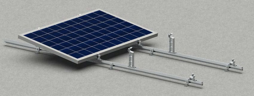
Planning

2. Planning

2.1 Determine Concrete Compressive Strength
The minimum concrete compressive strength of the roof slab to be 20MPa.

2.2 Determine Anchor Stud Specifications
The minimum pull-out capacity of the anchor studs should be 6.1kN to withstand the forces on the
mounting system. The corresponding anchor stud embedment to achieve this capacity should be
determined from manufacturer’s datasheet.

For instance, when using Ramset ChemSet™ Anchor Stud, a minimum embedment of 80mm into the
concrete slab is required to achieve 6.1kN minimum pull-out capacity.

2.3 Determine the Wind Region of your Installation Site

Region Definition:                                                              • Some areas are designated Region B (52 m/s).
                                                                                  Local authorities will advise if this applies in your
Wind regions are pre-defined for the whole of                                     area.
Australia by the Australian Standard 1170.2.
The Wind Region is an independent factor of                                     • Region C areas (64 m/s) are generally referred to
surrounding topography or buildings.                                              as Cyclonic and are generally limited to northern
• Most of Australia is designated Region A which                                  coastal areas. Most Region C zones end 100km
  indicates a Regional Wind Velocity of 43 m/s with                               inland.
  wind average recurrence of 200 years.                                         • Region D (79 m/s) is Australia's most extreme
                                                                                  Cyclonic Region, located between the town of
                                                                                  Carnarvon and Pardoo Station in Western
                                                                                  Australia.
Installation Guide_ PV-ezRack SolarRoof ChemSet Anchor Stud V1.0 (March 2021)                                                 page 02 of 19

    Unit 1, 10 Duerdin St, Clayton VIC 3168, Australia
    Tel: +61 3 9239 8088 Fax: +61 3 9239 8024
    E-mail: tech@clenergy.com.au www.clenergy.com.au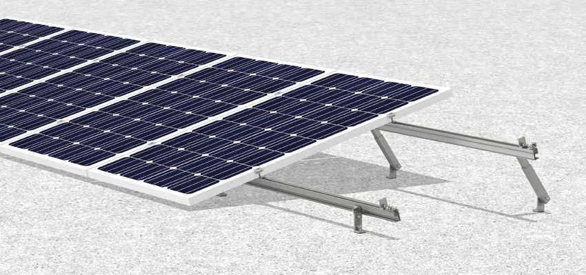
Planning

2.4 Determine the Terrain Category

You will need to determine the terrain category to ensure the installation meets the required standard.

Terrain Category 1 (TC1) – Very exposed open terrain with few or no obstructions and enclosed, limited-
sized water surfaces at serviceability and ultimate wind speeds in all wind regions, e.g. flat, treeless,
poorly grassed plains; rivers, canals and lakes; and enclosed bays extending less than 10km in the wind
direction.

Terrain Category 1.5 (TC1.5) – Open water surfaces subjected to shoaling waves at serviceability and
ultimate wind speeds in all win regions, e.g. near-shore ocean water; larger unenclosed bays on seas and
oceans; lakes; and enclosed bays extending greater than 10km in the wind direction. The terrain height
multipliers for this terrain category shall be obtained by the linear interpolation between the values for the
TC1 and TC2.

Terrain Category 2 (TC2) – Open terrain, including grassland, with well-scattered obstructions having
heights generally from 1.5m to 5m, with no more than two obstructions per hectare, e.g. farmland and
cleared subdivisions with isolated trees and uncut grass.

Terrain Category 2.5 (TC2.5) – Terrain with a few trees or isolated obstructions. This category is
intermediate between TC2 and TC3 and represents the terrain in developing outer urban areas with
scattered houses, or larger acreage developments with fewer than ten buildings per hectare. The terrain-
height multipliers for this terrain category shall be obtained by linear interpolation between the values for
the TC2 and TC3.

Terrain Category 3 (TC3) – Terrain with numerous closely spaced obstructions having heights generally
from 3m to 10m. The minimum density of obstructions shall be at least the equivalent of 10 house sized
obstructions per hectare, e.g. suburban housing or light industrial estates.

Terrain Category 4 (TC4) – Terrain with numerous larger, high (10m to 30m tall) and closely-spaced
constructions buildings, such as large city centers and well-developed industrial complexes.

If your installation site is not at TC 2, 2.5 or 3, please contact Clenergy to obtain a project specific
engineering certificate to support your installation.

2.5 Verify Atmospheric Corrosivity Zone of Installation Site

Please refer to “AS 4312-2008 Atmospheric Corrosivity Zones in Australia” or consult local construction
business to verify corrosivity category of installation site to determine appropriate products and interface
spacing. When standard products are installed in high corrosivity zones, like C4/C5, interface spacing
reduction factor need to be applied. Please refer to the generic notes of Certification Letter for the details.

Installation Guide_ PV-ezRack SolarRoof ChemSet Anchor Stud V1.0 (March 2021)                         page 03 of 19

     Unit 1, 10 Duerdin St, Clayton VIC 3168, Australia
     Tel: +61 3 9239 8088 Fax: +61 3 9239 8024
     E-mail: tech@clenergy.com.au www.clenergy.com.au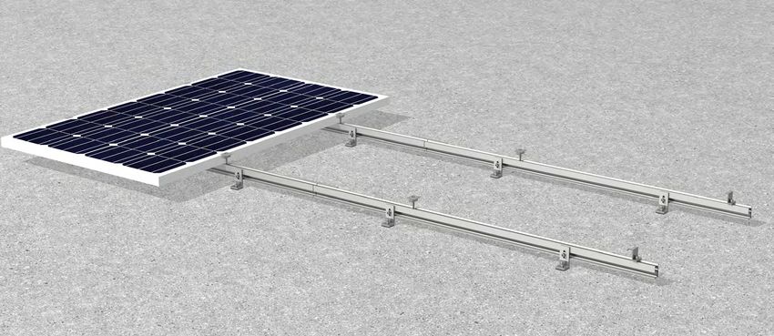
Planning

2.6 Determine the Installation Height, Installation Area and Maximum Interface Spacing

The installation height, area and interface spacing depend on the setup of the racking system.
Please refer to the generic certificates below based on the chosen mounting system setup:
      Product
    [Solar Roof
                                                                                Maximum Interface Spacing, Installation
     System +                        Generic Certificate
                                                                                          Height and Area
   Anchor Stud]

                                      Tin and Tile Certificate
 ChemSet™ Flush
                                         CL-088-S-REV H
                                                                                 The Generic Certificates on 2nd Column contains the
 ChemSet™ Tilt –                     Penetrative Tilt Certificate               installation height, area and spacings for the flush, tilt
 Adjustable Tilt Legs                        CL-530-S                           and commercial tilt (ComT) systems, which applies to
                                                                                   ChemSet™ Flush and Tilt systems, respectively.
 ChemSet™ Tilt –             Penetrative Commercial Tilt Certificate
 Commercial Tilt                          00150-REVB

2.7 Verify Maximum Rail End Overhang
Rail end overhang should be not over 40% of the interface spacing. For example, if the interface
spacing is 1500mm, the Rail end overhang can be up to 600mm only.

2.8 Acquire PV Modules Clamping Zone Information
It is recommended to acquire PV modules clamping zone info. from PV modules manufacturer, which
can help to plan interfaces positions on the roof and rails orientation and positions.

Installation Guide_ PV-ezRack SolarRoof ChemSet Anchor Stud V1.0 (March 2021)                                                         page 04 of 19

    Unit 1, 10 Duerdin St, Clayton VIC 3168, Australia
    Tel: +61 3 9239 8088 Fax: +61 3 9239 8024
    E-mail: tech@clenergy.com.au www.clenergy.com.au
Tools and Components

3. Tools and Components
3.1 Tools
                                                                           Tools

         Screw Driver                               Torque Spanner                        Spanner                     5m Tape
(for M8 Hexagon Socket Screw)

     ChemSet™ Anchoring Kit                         String & Marker Pen

3.2 Components
                                                                   Component list
                                                             - Manufacturer: Clenergy -

          ER-EC-ST                                 ER-IC-ST                          C-U/30/46-G              C-U/30/46
          End Clamp                               Inter Clamp                       Universal Clamp        Universal Clamp
                                                                                    with Grounding

     ER-EC-DU35/40                           ER-EC-DU40/46                             ER-R-ECO               ER-SP-ECO
  End Clamp, Dual 35 or                   End Clamp, Dual 40 or                         ECO Rail          Splice for ECO Rail
         40mm                                    46mm

            ER-I-05                              ER-I-05/CM                        ER-I-05A/EZC/ECO        ER-TL-10/15/PS
         Tin Interface                     Tin Interface with Click                Tin Interface A with    ER-TL-15/30/PS
                                                   Module                          ezClick connection     Adjustable Tilt legs,
                                                                                                             preassembly
Installation Guide_ PV-ezRack SolarRoof ChemSet Anchor Stud V1.0 (March 2021)                                             page 05 of 19

     Unit 1, 10 Duerdin St, Clayton VIC 3168, Australia
     Tel: +61 3 9239 8088 Fax: +61 3 9239 8024
     E-mail: tech@clenergy.com.au www.clenergy.com.au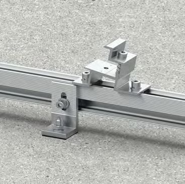
Tools and Components

                                                                    Component list

                                                             - Manufacturer: Clenergy -

     TL-10/15/L/PS                            ER-TL-5/PS                       FL-COMT/Z/G/10             RL-COMT/Z/G/10
     TL-15/30/L/PS                           ER-TL-10/PS                     Front Leg Assembly,     Rear Leg Assembly, 10°, with
Adjustable Tilt Legs with                   Fixed Tilt Legs,                10°, with Z-Module and    Z-Module and Grounding
  L-feet, preassembly                        preassembly                        Grounding Pins                  Pins

       EZ-GC-ST                                    EZ-GL-ST
     Grounding clip                              Grounding Lug

                                                             - Manufacturer: Ramset* -

ChemSet™ Anchor                             Anchoring Adhesive*
Stud* M8x110mm

*Non-Clenergy components are to be sourced externally. The technical specifications of these
components can vary one manufacturer to the other.

In order to source anchor studs with similar specification, please refer to section 2.2 for information on
the required technical specifications.

Installation Guide_ PV-ezRack SolarRoof ChemSet Anchor Stud V1.0 (March 2021)                                           page 06 of 19

    Unit 1, 10 Duerdin St, Clayton VIC 3168, Australia
    Tel: +61 3 9239 8088 Fax: +61 3 9239 8024
    E-mail: tech@clenergy.com.au www.clenergy.com.au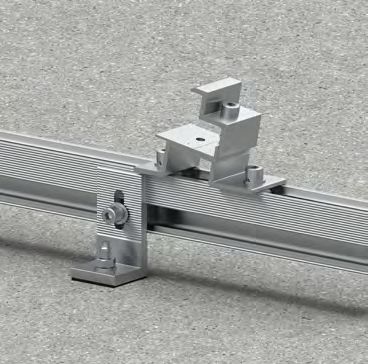
System Overview

4. System Overview
4.1 Overview of PV-ezRack SolarRoof
- With Tin Interface

                                                                       2                                                              4

                                                                   3                                              1                   5

 1 End Clamp               2 Inter Clamp              3 ECO Rail                4 Tin interface   5 Anchor Stud

- With Tilt Legs

                                                                                            2
                                                                                                            1

                                                                                                      4
                                                                       3
                                                                                                                                 5
                                                                                                                      4

 1 End Clamp                  2 Inter Clamp                3 ECO Rail               4 Tilt Legs   5 Anchor Stud

Installation Guide_ PV-ezRack SolarRoof ChemSet Anchor Stud V1.0 (March 2021)                                         page 07 of 19

     Unit 1, 10 Duerdin St, Clayton VIC 3168, Australia
     Tel: +61 3 9239 8088 Fax: +61 3 9239 8024
     E-mail: tech@clenergy.com.au www.clenergy.com.au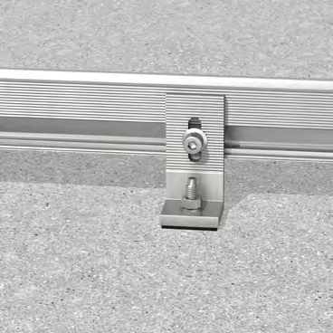
System Overview

- With ComT

- With ComT

                                                                                               2

                                                                                    3

 1 Front Leg Assembly                   2 Rear Leg Assembly                     3 ECO Rail   4 Tin interface
5 Anchor Stud
                                                                                                                           1

                                                                                                               4
                                                                                                                   5

- With ComT East-West

                                                                                                   2

                                                                                              3

                                                                                                                                       1

                                                                                                                   4
 1 Front Leg Assembly                   2 Rear Leg Assembly                     3 ECO Rail   4 Tin interface           5
 5 Anchor Stud

Installation Guide_ PV-ezRack SolarRoof ChemSet Anchor Stud V1.0 (March 2021)                                          page 08 of 19

    Unit 1, 10 Duerdin St, Clayton VIC 3168, Australia
    Tel: +61 3 9239 8088 Fax: +61 3 9239 8024
    E-mail: tech@clenergy.com.au www.clenergy.com.au
System Overview
4.2 Precautions during Stainless Steel Fastener Installation
Improper operation may lead to deadlock of Nuts and Bolts. The steps below should be applied to stainless
steel nut and bolt assembly to reduce this risk.
4.2.1 General installation instructions:
(1) Apply force to fasteners in the direction of thread
(2) Apply force uniformly, to maintain the required torque
(3) Professional tools and tool belts are recommended
(4) In some cases, fasteners could be seized over time. As an option, if want to avoid galling or seizing of thread, apply
lubricant (grease or 40# engine oil) to fasteners prior to tightening.
4.2.2 Safe Torques
Please refer to safe torques defined in this guide. When fixing mid and end clamps, if the torques range specified by
the panel manfuacturer is different, it should be used instead. In case power tools are required, Clenergy recommends
the use of low speed only. High speed and impact drivers increase the risk of bolt galling (deadlock) If deadlock
occurs and you need to cut fasteners, ensure that there is no load on the fastener before you cut it. Avoid damaging
the anodized or galvanized surfaces.
Installation Guide_ PV-ezRack SolarRoof ChemSet Anchor Stud V1.0 (March 2021) page 09 of 19
Unit 1, 10 Duerdin St, Clayton VIC 3168, Australia
Tel: +61 3 9239 8088 Fax: +61 3 9239 8024
E-mail: tech@clenergy.com.au www.clenergy.com.auInstallation Instruction
5. Installation Instructions
The installation instructions vary based on the mounting system setup for the PV system.
Please refer to the navigation guide below for corresponding to the relevant sections of the installation
process in the following pages:
I. ChemSet™ Anchor Stud Installation
This step is common for any PV mounting system setup, explained in section 5.1.
II. Choice of Mounting System Interface
This varies based on the panel orientation of the PV system as follows:
a.Solar Roof Flush [detailed in section 5.2]
Panels are flush to the roof surface.
Tin Interfaces and Anchor Studs are utilised for this setup.
b.Solar Roof Adjustable Tilt [detailed in section 5.3]
Panels are tilted to the roof surface using adjustable tilt legs.
Tilt legs and Anchor Studs are utilised for this setup.
c.Solar Roof ComT [detailed in section 5.5]
Panels are tilted to the roof surface using commercial tilt legs.
Commercial Tilt [ComT] legs and Anchor Studs are utilised for this setup.
III. Rail Installation
Based on the chosen interface, the rail installation to interface varies:
a.Flush and Adjustable Tilt Leg systems – Please visit section 5.4 for details.
b.Commercial Tilt systems – Please visit section 5.5 for details.
IV. PV Module Installation
The PV modules are clamped based on the chosen mounting system:
a.Flush and Adjustable Tilt Leg systems – Please refer to our PV-ezRack® Grounding System
manual for details.
b.Commercial Tilt systems – Please visit section 5.5 for details.
V. System Grounding
Please refer to our PV-ezRack® Grounding System manual for information on our mounting system
grounding process.
Installation Guide_ PV-ezRack SolarRoof ChemSet Anchor Stud V1.0 (March 2021) page 10 of 19
Unit 1, 10 Duerdin St, Clayton VIC 3168, Australia
Tel: +61 3 9239 8088 Fax: +61 3 9239 8024
E-mail: tech@clenergy.com.au www.clenergy.com.auInstallation Instruction
5.1 ChemSet™ Anchor Stud Installation
5.1.1 Drill a hole with a diameter of 10mm and a depth
between 80 and 90mm.
5.1.2 Remove dust and debris by brushing and blowing
3 times each as shown in Figure 5.1A (If hole is wet or
flooded, remove excess water with wet/dry vacuum).
Figure 5.1A
5.1.3 Screw mixing nozzle onto cartridge and dispense
2-3 trigger pulls of adhesive to wait until colour is green
/ grey with no streaks
5.1.4 Insert mixing nozzle to bottom of hole. Fill hole
with adhesive to 3/4 the hole depth slowly, ensuring no
air pockets form as shown in Figure 5.1B.
Figure 5.1B
5.1.5 Insert Ramset™ ChemSet™ Anchor Stud/rebar to
bottom of hole while turning as shown in Figure 5.1B.
5.1.6 Wait until adhesive has fully cured before loading
as shown in Figure 5.1C.
Figure 5.1C
Installation Guide_ PV-ezRack SolarRoof ChemSet Anchor Stud V1.0 (March 2021) page 11 of 19
Unit 1, 10 Duerdin St, Clayton VIC 3168, Australia
Tel: +61 3 9239 8088 Fax: +61 3 9239 8024
E-mail: tech@clenergy.com.au www.clenergy.com.auInstallation Instruction
Note: Load should not be applied to anchor
until the adhesive has sufficiently cured as
specified in Figure 5.1D.
Figure 5.1D
5.2 Tin Interface Installation
Connect and adjust tin foot position on the
anchor stud. Tighten with washer and nut as per
manufacturer’s instruction.
The interface base should sit flat on the roof
surface. For any required clearance between
interface base and roof surface, please contact
engineering@clenergy.com.au.
Figure 5.2A
5.3 Tilt Legs Installation
5.3.1 Front Leg Installation:
Connect and adjust front tilt leg position on
the anchor stud, as shown in Figures 5.3A
and 5.3B. Tighten with washer and nut as per
manufacturer’s instructions.
Figure 5.3A
Figure 5.3B
Installation Guide_ PV-ezRack SolarRoof ChemSet Anchor Stud V1.0 (March 2021) page 12 of 19
Unit 1, 10 Duerdin St, Clayton VIC 3168, Australia
Tel: +61 3 9239 8088 Fax: +61 3 9239 8024
E-mail: tech@clenergy.com.au www.clenergy.com.auInstallation Instruction
5.3.2 Rear Leg Installation:
According to the installation plan, after confirming
the length L of the Rear Leg, fasten washer, nut and
M8*12 bolts as shown in Figures 5.3C and 5.3D.
Two Ramset™ ChemSet™ Anchor Studs are used
to install rear leg.
Recommended torque for M8*12 bolts is 16~20 Figure 5.3C
N·m
The tilt leg base should sit flat on the roof surface.
For any required clearance between interface base
and roof surface, please contact
engineering@clenergy.com.au.
Figure 5.3D
5.4 Rail Installation
5.4.1 To connect several rails together, slide
half of the splice into the rear side of the
rail. Fasten the first M8 Bolt using an Allen
key, and slide the next rail into the splice as
shown in Figure 5.4A. Tighten the second M8
Bolt using an Allen key. The total rail length
is recommended not to be over 30 meters
considering rails thermal expansion problem.
Splice provides the electrical connection
between the 2 rails through the pressure bolts.
This eliminates the need of using 2 earthing
lugs Figure 5.4A
Recommended torque is 10 ~12 N·m.
5.4.2 After confirming the position of rail, fasten
with Tin Interface or Front and Rear Leg, as
shown in Figure 5.4B.
Recommended torque for M8 bolts is 16~20
N·m.
Figure 5.4B
Installation Guide_ PV-ezRack SolarRoof ChemSet Anchor Stud V1.0 (March 2021) page 13 of 19
Unit 1, 10 Duerdin St, Clayton VIC 3168, Australia
Tel: +61 3 9239 8088 Fax: +61 3 9239 8024
E-mail: tech@clenergy.com.au www.clenergy.com.auInstallation Instruction
5.5 ComT Installation
5.5.1 Fix the Front Leg into the top channel of ECO Rail, then fasten the Front Leg after the position is
adjusted properly as shown in Figures 5.5A and 5.5B
Recommended torque for M8 bolts is 16-20 N·m.
Figure 5.5A Figure 5.5B
5.5.2 Fix the Rear Leg into the top channel of ECO Rail, then fasten the Rear Leg after the position is
adjusted properly as shown in Figures 5.5C, 5.5D and 5.5E.
Recommended torques: M8 Bolt:16-20 N·m.
Figure 5.5C
Figure 5.5D South/North facing solution Figure 5.5E East-West facing solution
Installation Guide_ PV-ezRack SolarRoof ChemSet Anchor Stud V1.0 (March 2021) page 14 of 19
Unit 1, 10 Duerdin St, Clayton VIC 3168, Australia
Tel: +61 3 9239 8088 Fax: +61 3 9239 8024
E-mail: tech@clenergy.com.au www.clenergy.com.auInstallation Instruction
Figure 5.5F
5.5.3 Place the PV Modules on the Front and Rear
Leg as shown in Figure 5.5F. The outside edge
of the frame of the PV Modules must overlap the
marking lines on the Front and Rear Legs as shown
in Figure 5.5G. The pins of Front and Rear legs
are used for creating earthing continuity from PV
modules to both legs.
Figure 5.5G
5.5.4 Fix the clamp on the Rear Leg shown in
Figure 5.6H and fasten the clamps of Front and
Rear legs till the PV Modules are properly installed
in Figure 5.5I. Recommended torques: M8 Bolt: 16-
20 N·m.
Figure 5.5H
5.5.5 Repeat the above steps to install other Front
and Rear Legs, and PV modules.
Figure 5.5I
Installation Guide_ PV-ezRack SolarRoof ChemSet Anchor Stud V1.0 (March 2021) page 15 of 19
Unit 1, 10 Duerdin St, Clayton VIC 3168, Australia
Tel: +61 3 9239 8088 Fax: +61 3 9239 8024
E-mail: tech@clenergy.com.au www.clenergy.com.auCertification Letter and
Interface Spacing Table
Installation Guide_ PV-ezRack SolarRoof ChemSet Anchor Stud V1.0 (March 2021) page 16 of 19
Unit 1, 10 Duerdin St, Clayton VIC 3168, Australia
Tel: +61 3 9239 8088 Fax: +61 3 9239 8024
E-mail: tech@clenergy.com.au www.clenergy.com.auPV-ezRACK® 10 Year Product Warranty
As the manufacturer of quality solar mounting systems, Clenergy Australia provides a warranty for all PV-ezRack products it supplies in Australia and New
Zealand (“Products”). The warranty provided by Clenergy Australia is subject to the conditions contained in this document (“Warranty”). No other warranty
provision implied or otherwise is to be assumed. Your Warranty coverage is in accordance with this document.
Product Warranty Table for Installations in Corrosivity Category 1, 2, 3, 4 and 5 (ISO 9223)
Product Warranty
Standard or
# Product Material Customized Corrosivity
Corrosivity Corrosivity
Product Category 1,
Category 4 Category 5
2 and 3
6005CL-T5 mill finish Standard 10 years 10 years* 10 years*
Aluminium 6005-T5 anodized to 10 microns Standard 10 years 10 years* 10 years*
1
Components 6005-T5 anodized to 15 microns Customized 10 years 10 years 10 years*
6005-T5 anodized to 20 microns Customized 10 years 10 years 10 years
Galvanized Steel
2 Galvanized Steel at 85 microns in average Standard 10 years 10 years Not warranted
Components
Stainless Steel
3 SUS304 Standard 10 years 10 years 10 years
Components
Fasteners (bolts/ SUS304 Standard 10 years 10 years 10 years
4
nuts/washers) SUS316 Customized 10 years 10 years 10 years
Buildex Screws for
5 Carbon Steel SAE 1022 with Climaseal 3 Finish Standard 10 years 10 years** 10 years**
Tile Interface
Buildex Screws for
6 Carbon Steel SAE 1022 with Climaseal 3 Finish Standard 10 years Not warranted
Tin Interface
* Subject to interface spacing reduction as advised by Clenergy Australia. Please contact us for more details.
**The screws under tile interface are assumed to be installed a category 1, 2 or 3 micro-climate within the roof structure.
Warranty Scope:
Your solar mounting Product has been manufactured to high standards, however, should any manufacturing defect arise, please contact Clenergy
Australia. We will arrange for an inspection of the affected Product(s) to determine the extent of the problem.
Details are provided below as to the extent of your Warranty coverage and any exclusions that may apply. Please read these provisions carefully to ensure
you receive the appropriate assistance and support in a timely manner. Please also contact Clenergy Australia if any part of this Warranty is unclear, or
you wish to discuss your rights and remedies under this Warranty.
If your Product fails during the Warranty periods set out in the Warranty table above due to a defect in:
(a) materials and/or workmanship on and from the date of the Product’s delivery; or
(b) structural integrity on and from the date of the Product’s installation,
Clenergy Australia will at its election either repair or resupply the defective Product provided that:
• The Product was installed correctly by a Clean Energy Council (“CEC”) accredited or equivalent accreditation installer, following the Clenergy installation
manual provided at time of purchase.
• The Product has been maintained correctly in accordance with section “Care of your Product” below.
Warranty Conditions:
• Any and all costs for repair or replacement outside the Warranty period are the responsibility of the customer.
• Where Clenergy attends a site and finds that the Product is not faulty, the costs for the visit will be payable by the customer.
• Defective Products shall be uninstalled and/or reinstalled at the customer´s expense and risk.
• Under certain conditions, the Warranty can be extended to more than 10 years at an extra cost, available upon request.
Warranty Exclusions:
• Product finish (natural surface oxidation) or any natural impairment or surface corrosion that does not compromise the structural integrity.
• Products sold or installed outside of Australia and New Zealand unless approved previously in writing by Clenergy Australia.
• Damage caused by transport, mishandling, incorrect storage, improper loading or willful conduct.
• Any Product not correctly installed in accordance with our installation manual, or any specific design instruction or special conditions as advised by
Clenergy Australia.
• Damage caused by the Product being modified in any way unless previously agreed to in writing by Clenergy Australia.
• The use of the Product for purposes other than the mounting of PV solar panels.
• Installations where the environment is excluded in the “Products Warranty Table” above, and for galvanized steel ground system Products, where the pH
level is outside the range of 6-8, unless agreed to in writing by Clenergy Australia prior to installation.
Installation Guide_ PV-ezRack SolarRoof ChemSet Anchor Stud V1.0 (March 2021) page 18
17 of 19
Unit 1, 10 Duerdin St, Clayton VIC 3168, Australia
Tel: +61 3 9239 8088 Fax: +61 3 9239 8024
E-mail: tech@clenergy.com.au www.clenergy.com.auPV-ezRACK® 10 Year Product Warranty
• Damage caused by extreme weather conditions or any other natural or man-made event outside of our control.
• Damage caused by attachments not designed or approved for connection to the Product.
• Damage caused by lightning strikes or excessive currents through the earthing/grounding clamps, clips or lugs.
Our Products may come with guarantees that cannot be excluded under the Australian Consumer Law. You may be entitled under statute to a replacement
or refund for a major defect in the Products. You may also be entitled under statute to have the products repaired for any defect which does not amount to
a major defect. The benefits given by this Warranty are in addition to any statutory rights and remedies you may have under Australian law.
Product Care:
Clenergy Products are designed to be durable with minimal care, however it is important that you maintain your mounting Product in accordance with
proper practices. This includes regular maintenance and inspection to avoid damage.
The aluminum components are made from either AL 6005CL-T5 or AL6005-T5 and may also have a clear anodization. The aluminum may undergo some
surface oxidization in service. Please note that this is normal and part of the natural ageing process. The result may even be beneficial to the longevity of
the Product, as the oxidization can provide additional protection against degradation by pollution and atmospheric corrosion.
• The torque values of fastener connections on mounting system must be checked annually and corrected if needed in accordance with Clenergy
Australia’s installation manual.
• Regular cleaning to remove any soil or other possible contaminants must also be performed. Cleaning should be performed in accordance with
guidelines recommended by the Galvanizers Association of Australia (GAA) (for Products supplied in Australia) or the Galvanizers Association of New
Zealand (GANZ) (for Products supplied in New Zealand) or any other similar organisations (as applicable). When using tin interfaces for installation
works, screws not exposed to frequent rain should be washed down with fresh water at least every 6 months.
• You should not use harsh chemicals or highly abrasive materials that may damage Product surfaces. Use only cleaners that are designed for aluminium
and always wash them off with clean water afterwards. Steel components should be inspected before and after installation and any damage to the
galvanizing should be treated immediately to prevent rusting. It is normal for galvanized Products to develop a surface barrier (the ‘patina’), which helps
to protect the surface from contaminants in the atmosphere and does not adversely affect the Product.
• You should also ensure that if the Product is stored prior to installing that it is not contaminated by contact with rusty items or other impurities such as
dirt and chemicals. Should this occur, you must clean the Product and make any repairs using approved methods such as galvanized paint and antirust
treatments immediately before installation.
Installation Guide_ PV-ezRack SolarRoof ChemSet Anchor Stud V1.0 (March 2021) page 18
19 of 19
Unit 1, 10 Duerdin St, Clayton VIC 3168, Australia
Tel: +61 3 9239 8088 Fax: +61 3 9239 8024
E-mail: tech@clenergy.com.au www.clenergy.com.auClenergy Australia Clenergy Thailand
1/10 Duerdin Street, Clayton VIC 3168 Australia 9/2, 5th Floor, Vorasin Building, Soi Yasoob 2, Viphavadee-Rungsit
Tel: +61 3 9239 8088 Fax: +61 3 9239 8024 Road, Chomphon Sub-district, Chatuchak District, Bangkok 10900
E-mail: sales@clenergy.com.au Tel: +66 (0) 2 277 5201, +66 (0) 6 3228-0200
www.clenergy.com.au E-mail: sales_th@clenergy.com, support_th@clenergy.com
www.clenergythailand.com
Clenergy China
999-1009 Min’an Rd, Huoju Hi-tech Ind. Dev. Zone Clenergy Singapore
Xiang’an District 361101, Xiamen, Fujian, China 24 Raffles Place #28-01 Clifford Centre Singapore 048621
Tel: +86 592 311 0088 Fax: +86 592 599 5028 Tel: +65 9743 1425
E-mail: sales@clenergy.com.cn E-mail: vincent.chan@clenergy.com
www.clenergy.com.cn
Clenergy Malaysia
Clenergy EMEA Tel: +86 18750231005
Esplanade 41, 20354 Hamburg, Germany E-mail: sales_em@clenergy.com
Tel: +49 (0) 40 3562 389 00
E-mail: sales.emea@clenergy.com Clenergy Vietnam
Tel: +86 592 3110095
Clenergy Japan E-mail: sales_vietnam@clenergy.com;
Nittochi Yamashita Building 5th Floor susie.chen@clenergy.com
23 Yamashita-cho, Yokohama, 231-0023 Japan
Tel: +81 45 228 8226 Fax: +81 45 228 8316 Clenergy Korea
E-mail: sales@clenergy.co.jp Tel: +8210-4684-8088
www.clenergy.jp
E-mail: sales.kr@clenergy.com
Clenergy Philippines
145 Yakal St., San Antonio village, Makati City, Philippines
Tel: +63 977 8407240
E-mail: sales_ph@clenergy.com
Worldwide Network
www.clenergy.ph
Germany
Japan
South Korea
China
Warranty Thailand Philippines
Vietnam
Singapore
Clenergy Installation Guide_PV-ezRack SolarRoof
ChemSet Anchor Stud V1.0 (March 2021)
AustraliaYou can also read