Yale Smart Home Alarm Manual - The smarter way to protect your home
←
→
Page content transcription
If your browser does not render page correctly, please read the page content below

Conexis L1

           Yale Smart Home
           Alarm Manual•
           SR-310 • SR-320 • SR-330 • SR-340

ASSA ABLOY Group brand

                         The smarter way to protect your home•
smart
       Living

Control your home
security from your
smartphone

     The smarter way to protect your home•
2
Introduction

Contents
1. Location planning                                                    4
2. Un-pack & power devices                                              6
3. Initial set-up                                                     11
4. Mounting devices                                                   13
5. Using the system                                                   18
6. Default settings                                                   21
7. Adding & Using devices                                             22
8. Changing batteries                                                 26
9. Troubleshooting                                                    31
10. Specifications 		                                                 33

  For more information on this product and       The 2 year guarantee for this
  Yale Smart Living Range visit                  product is active from the
                                             2   date of purchase (A copy of
  www.yale.co.uk/smart-living
  Consumer Support:                              this guarantee is available on
  www.yale.co.uk/help                            our website).

                                                                                  3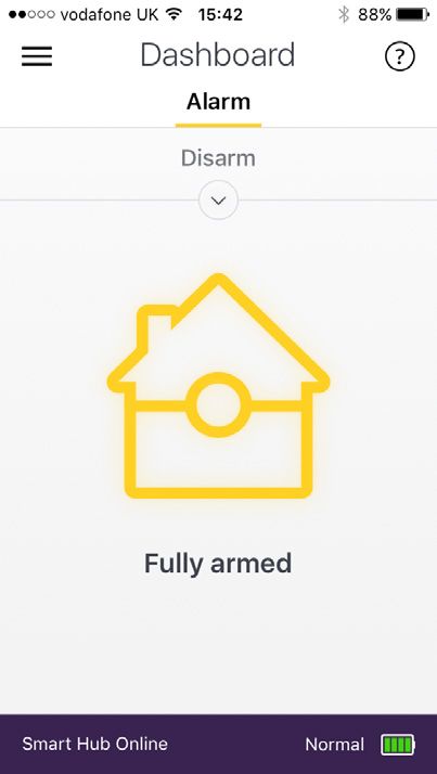
Location Planning•

    Plan device locations check devices range
                                        (12)
                                              before     mounting.
                                                (GB) Installation - (IT) Installazione - (DE) Installation - (NO) Installasjon - (SE
                                                                               (DK) Installation.
                                                                           7
                                                                       1                                 Key Pad
                                                                                                               2                                  b

    Operating 30m Range                                                                                  • The Key Pad should be
                                                                                                            accessible from a protected
    All devices must be within 30 metres of the Smart Hub and                                               entry/exit point
    must not be mounted on or near large metal objects. Avoid                                            • Ensure that the Key Pad is
    obvious sources of electrical interference such as fridges and                                          not visible from the outside of
    microwave ovens.                                                                                        the premises.

                                                                       3

                                                                                                                                              a

                                                                                                      Ø 3.5mm

                                                                                                                                              d

                                                                       4

                                                                                                         a
                                                                                       Ø 5mm
                                                                                   b

                                                                                               c

                                                                       5                                                 6

                                                                                                   Panic Button
                                                                                                   The Panic Button can activate your alarm
                                                                                                   immediately - even when the system is
                                                                                                   disarmed.
                                                                                             • Keep out of reach of children
                                                                                   • Keep hidden from view, but easily accessible.

    Information and illustrations are subject to change within this
    document. Yale reserves the right to alter the specification and
    product design at anytime without notice. Yale® is a registered
    trademark. © 2017 ASSA ABLOY. All rights reserved.

4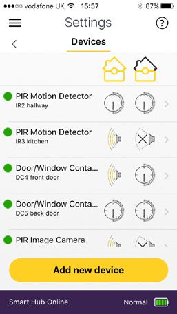
(GB) Step by step index -
                                                                                                                                                                                (03)

                                                                                        1
                                                                                       Accessories vary depending on kit

                                  Smoke Detector
                                                                                                                                                                                    External Siren
                            arn
                    tery Le
                 Bat Off>
                   n
              r

                                                                              Mount on a ceiling in main                                                                            Mount as high as possible, out of

    • Mount 1.8m - 2.1m above floor level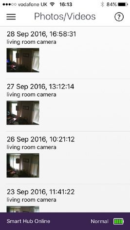
Unpacking the devices•
                                                                                                    ar   n
                                                                                              ry Le
                                                                                       BantteOff>

                                           er
                                        Pow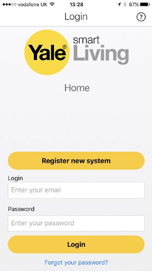
(GB) Installation - (IT) Installazione - (DE) Installation - (NO) Installasjon -
                                   (DK) Installation.
      Keypad
                                                                                                  Remove battery strips (1

                                                                         Panic button A
                                                 Yale
                                                                         Panic button B
                                                                         LED
                                                  1      2        3
                                                                         Learn button=
                                                  4      5        6      Press 8 and 9 together
                              Away                7      8        9

 ) Installazione - (DE)0 Installation - (NO) Installasjon - (SE) Ins
                                 /                                       Disarm
                                                                         HomeArm

                                      Test your planned location of components (2
      See page 16 for Key pad installation.

                         Remove battery strips (1
      PIR
                                                                      Yale

                                         Status
                                         LED                          Press button to test connection (3

                                              Learn/Test button                           Cover
                                                                                          screw
                                                                  (GB) Installation - (IT) Installazione - (DE) Installation
                                                                  (DK) Installation.

      Door Contact                            8 9                                                                   Remove battery strips (
ocation of components (2
                                                      LED

                                                                      Learn/Test
                                      Yale

                     Sensor                                           button

                                                                      Gap no more
                     Magnet                                           than 10mm

                  6
button to test connection
                        Test(3your planned location of components (2

                                                                                                                                    7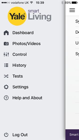
a

            Unpacking the devices•                                                                                                                           Ø 5mm
                                                                                                                                                                     c

                                                                                                                                                      (21)

            External Siren
                                          (GB) Installation - (IT) Installazione - (DE) Installation - (NO) Installasjon - (SE) Installation -
                                          (DK) Installation.
                                                                                                                                                 7
                                                                                                                                                     2.4                     5
            WARNING                      1                                                        1.2                             a

            The Siren is very loud! Take care not to activate                                                       b                                                            b

            the Siren tamper switch unnecessarily.

                                         3

               (GB) Installation - (IT) Installazione - (DE) Installation - (NO) Installasjon - (SE) Installation -
               (DK) Installation.                         b                a

            PIR Image Camera                                                                                                                     d                           5
               				c
                                             Ø 5mm              Remove battery strips (1

                                                                          Learn/Test button

                                         4                                               5                              a         6
                                                                          Flash light
                                                                                              b

                                                                          Camera
                                                       Learn: Hold for 10 seconds                                                                    (11)
 ) Installazione Test your
                 - (DE)    planned location
                        Installation          of components
                                                       Test: Hold for 1 second
                                     - (NO) Installasjon - (SE)(2Installation -

            PIR Video Camera                                                                                                      5
             Remove battery strips (1

                                                                           Flash light
                                   Press button to test connection (3

                                                                           Camera

                                                                           Learn/Test button
                                                    Learn: Hold for 10 seconds
                                                    Test: Hold for 1 second
ocation of components (2

            Power Switch
            Plug in to mains socket.
                     8 9

button to test connection (3

                                                                                                                            On/Off, Test &
                                                                                                                            Learn button

                                                                                                  Learn: Hold for 10 seconds
                                                                                                  Power On/Off: Press & release
                                                                                                  Test: Press & release

        8             6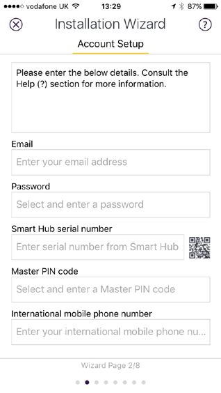
3 x 1.5v AA
                       3 x 1.5v AA
                   (Lithium)
                        (Lithium)

                  3 x 1.5v AA
 SR-PVC SR-PVC
Key Fob            (Lithium)

          1.                         2.                  3.
                                          CR 2032
SR-PVC                                    CR 2032

                                          CR 2032

          SR-KF

Smoke
 SR-KF Detector

                                           3 x 1.5v AA

SR-KF                                     3 x 1.5v AA

          SR-SD
                                          3 x 1.5v AA
 SR-SD                                         CR 2032

Panic Button
                                               CR 2032
SR-SD

          SR-PB
                                               CR 2032

 SR-PB

SR-PB

                                                              9
Download the app•
                     (08)
 Please ensure all devices
                       (DE) Appare   powered              and
                       (GB) App download - (IT) Scarica l'App -
                                Download - (NO) Nedlasting       operational
                                                             av App                       at- this point.
                                                                    - (SE) Installera appen
                                    (DK) Installer APP.
                                3

 (08)

          Download          the -Yale
                                 Yale     Home        App
                 (GB) App download - (IT) Scarica l'App -
             (DE) App Download    (NO) Smart  Living
                                       Nedlasting     Home
                                                  av App - (SE) Installera appen -
             (DK) Installer APP.
             3
          Internet Connection: Required on
                                                                                                            iOS 9 +          Android 4.2 +
                   Yale Smart Living Home
                                                            IOS 9.0 +

                                                          Android 4.2 +

        First time registration
                         IOS 9.0 +

        Follow the set-up instructions in the app.

                                     Android 4.2 +

                                                                Serial No.

                                             Serial No.
                                                                                        Please Note:
                                                                                     Panel Serial NumberSerial
                                                                                                         can beNo.
                                                                                     found on the Smart Hub sticker.

                              Please register the hub within one hour of power up, otherwise app ‘authentication error’ will appear
                              – re-boot the hub (including switching off / on the back-up battery) and start the process again if
                              necessary.

                Recording your set-up information
                  E-mail used to set up system:
                  Smart Security Hub 2.0 serial number
                  Phone number used for notifications:
                  Keypad PIN Code for Disarm/Arm (default 1234):
                  Keypad code for keypad setting (default 0000):

10
Setting up devices•
Adding new devices (Optional: Use it only if you have extra devices outside the kit)
All devices in the kit are linked to the Smart Hub. If you want to add more devices, you can do this by using the “Add new device”
section in the Smart Living Home app.
Go to the app menu
Setting > Alarm Setting > Devices and then press Add New Device button
1
Enter Learn Mode
2
Learn in Devices
Press the learn button on the device you leant to add then see diagrams below. The Smart Hub will beep (single or multiple
dependent on device) when a new device is registered. You will then see your new device in your device List within the home app.
Learn/ Test
button Learn/Test
Press & hold button
for 3 seconds One single
press.
Learn/Test
button Learn/Test
One single button
press.
EF-PETPIR One single
press.
Learn/Test button
One single press.
Learn/Test
Ensure you button
initialise your Press 8 and 9
keypad before together
you learn it in.
(See page 17)
LED Learn/Test button
One single press.
For the following accessories, please hold the Learn button for 10 seconds, before releasing to enter Learn mode.
Learn/Test button If the accessory doesn’t learn in, remove the batteries for 5 seconds, then replace
Hold for 3 seconds and try relearning within 3 minutes.
SR-PVC must be learned in with the
tamper screw removed so that the tamper
is open. Sensor will not learn with tamper
closed.
SR-PC SR-PVC Learn/Test button SR-PS Learn/Test button
Hold for 3 seconds Hold for 3 seconds
3 Exit Learn Mode:
Press Stop learning mode on the app
11(09)
(GB) Setting up - (IT) Configurazione - (DE) Einstellung -
(NO) Tilkobling og montering av alarmsentralen - (SE) Driftsättning -
Range Test•
(DK) Opsætning.
4
1
Check Accessories Range
1.) Place each device in the location where you wish to mount them.
er
Bantte
ar n
Pow
LAN
Before mounting each device. Please check the system with a simple range test.
Login to your Yale Home App. Select “Tests”, “Device List” then select “Walk Test”.
2 the devices in the desired location and press the Test/Learn
Hold 3 button on the accessories. (see page 9)
Router
If the sensor signal reached the Smart Hub, it will show in the device list on your app.
NOT INCLUDED
4
a
When you are happy that all your devices can communicate with the Smart Hub, please proceed to mounting the
accessories. Lea
rn
y
b
tery ter
er
Batn Off>
O
Before you mount a device use the device a
n Of ryMounting Devices•
PIR Motion Detector 1 2
b
a
3 a
b
~1.8m
2.1m
Ø 3.5mm
4
d
a
b
Ø 5mm
c
5 6
Key Pad 1 2 b
3
a
Ø 3.5mm
d
4
a
Ø 5mm
b
c
5 6
13Mounting Devices•
Door/Window Contact
(14)
(GB) Installation - (IT) Installazione - (DE) Installation - (NO) Installa
(DK) Installation.
7
1 2
a
1. The sensor should be on the frame while the magnet should be on the door/window.
Testing 3 4
The gap between the magnet and sensor should
be no more than 10mm when closed. Test to see
whether the magnet is in range of the sensor: before
mounting hold the magnet and sensor in place and
then pull them apart. If the sensor LED lights up it
implies the two items are within range. max 10mm
5
or
Clean the mounting surface with a suitable degreaser agent and mount using the adhesive pads
Please note that some surfaces may be unsuitable for mounting using the adhesive pads. Please use
screwmounting in these cases.
5
or
6 7
b
6 7
b
a
a
14Mounting Devices•
PIR Camera
b
1 2
c
a
3 a
b
Ø 3.5 mm
~1.8m
2.1m
4
b
d
a
c
Ø 5 mm
5 6
b
a
15Mounting Devices•
Mounting the External Siren (21)
(GB) Installation - (IT) Installazione - (DE) Installation - (NO) Installasjon - (SE) (21)Installation -
(GB) Installation - (IT) Installazione - (DE) Installation - (NO) Installasjon - (SE) Installation -
(DK) Installation.
The tamper spring is fully compressed when the siren is mounted. If there is a gap, pack with a
(DK) Installation.
suitable spacing material.
(21) 7
(GB) Installation - (IT) Installazione - (DE) Installation - (NO) Installasjon - (SE) Installation - 7
(DK) Installation.
1 2 a
1 7
Powering up 2 will
the siren a
1 1.2 a
b
automatically disable the siren
b
tamper for three hour period. b
3
3
2.
b a b a
3 d
d
c
Ø 5mm c
Ø 5mm
b a
4 5 a 6
b 4 5 a 6
d
b
c
Ø 5mm
3.4 4.5 a 6
b
161
Mounting Devices•
Pair / Test button
Panic Button
(IT) Associazione/test - (DE) Verbinden/Testen -
(NO) Tilkobling/Test - (SE) Para/Testa - (DK) Tilslut/test
1.1 2.
(GB) Installation - (IT) Installazione - (DE) Installation - (NO) Installasjon - (SE) Installation -
(DK) Installation. Ø 5mm
1 23.
Smoke
PairDetector
/ Test button (15)
(GB) Installation - (IT) Installazione - (DE) Installation - (NO) Installasjon - (SE) Installation -
(DK) Installation.
(IT) Associazione/test - (DE) Verbinden/Testen - 7
(NO) Tilkobling/Test - (SE) Para/Testa - (DK) Tilslut/test
1 2
3
Pair / Test button
(IT) Associazione/test - (DE) Verbinden/Testen -
(NO) Tilkobling/Test - (SE) Para/Testa - (DK) Tilslut/test
3
1 1 17Using the System•
Arming and Disarming your Alarm
Using the Yale Home App
Swipe Swipe down to Swipe down to
part arm fully arm
Changing your Key Pad PIN
The default Key Pad PIN is 1234. You can set up to 10 sets of 4 digit PIN numbers in the app:
18Using the System•
Configuring Device Behaviour
In your device list, go in to the settings for each device and select the required setting.
Setting up Part Armed Mode Disarmed Part-Armed Armed
Burglar
Part Armed mode is usually used to protect the ground floor when you are upstairs in bed.
Key
Home Omit
Disarmed Part-Armed Disarmed
Armed Part-Armed Armed
Burglar Burglar
Sensor
Disarmed
Home Access Part-Armed Ignored Armed
Burglar
Home Omit Home Omit
Entry Instant Siren
Home Access Home Omit
Home Access
Entry Home Access Triggers
Entry Countdown
Entry
19Using the System• Adding Alert Notifications You can add/delete email addresses that will be alerted when the alarm is triggered. You can choose to have ALL events (or Burglar only) reported via email. Hint: our report email will use the email address of: report@yalehomesystem.co.uk Save this email address as your VIP (Apple iOS) or Priority (Android) email and assign a special ringtone to it. You can also add SMS alerts to specified mobile numbers (burglar events only) 20
Default Settings•
                                                                                                                               Disarmed         Part-Armed
                                                                                                        Burglar

 All devices (except SR-PC and SR-
                                                                                                                                Key
 PVC) are pre-set to “entry” mode.                                                                      Home Omit
                                                                                                                 Disarmed     Part-Armed          Armed
 When the system is first armed, users will have 30
                                                                                         Disarmed    Part-Armed      Armed
                                                                Burglar                  Burglar
 seconds to exit the building. If the system is already
                                                                                                                                Sensor
 armed, triggering any sensors will cause an entry                                                       Disarmed
                                                                                                        Home  Access   Part-ArmedIgnoredArmed
                                                                               Burglar
 countdown to begin.                                            Home Omit                Home Omit

 SR-PC/SR-PVC’s default setting is “Burglar only”, i.e.                                                 Entry                Instant Siren
 immediate triggering during full arm and sleep during          Home Access    Home Omit
                                                                                      Home Access
 Part Arm. This is done to conserve battery life.

 You can change the device behaviour and length of the
                                                                Entry          Home Access                                     Triggers
                                                                                       Entry                                  Countdown
 entry timer within the home app.

                                                                               Entry

  Supervision off as default (recommended).
         Please note that having supervision enabled could reduce the battey life of your devices.

         This feature should only be used by a professional installer to check for outage and malfunctions with
         your devices. Incorrect usage would lead to a supervision failure message showing on the app.

         With the exception of the PIR Image Camera, PIR Video Camera and Smoke Detector (these always
         have supervision turned on), the other devices you will need to have supervision manually enabled on
         the device if required.
         Supervision can be enabled via Settings > System Settings > General Configuration.

   Jamming and interference                                               If jamming and interference is of concern, please
   detection (default on).                                                enable via “Controller” -> “Panel Setting”

                                                                                                                                           21
Adding & using devices•
Key Fob Key Pad
Initialisation
IMPORTANT: If you purchase a Key Pad seperately to your
kit, you will need to initialise it before you learn it in for use
/ with your Smart Hub.
Panic
Panic button A
Yale
Panic button B
Part Arm
LED
1 2 3
Learn button=
4 5 6 Press 8 and 9 together
Away 7 8 9
/ Disarm
0 HomeArm
Part arm
• Use the key fob to remotely arm, part arm or
disarm your alarm when within 30m range of
your Smart Hub. 1 Press ‘Panic button A’ followed by factory
• To add a Key Fob, see page 9. default Key Pad code ‘0000’.
• Pressing the panic button on the key fob will 2 The LED will now flash slowly indicating it is in
immediately sound the alarm. test (programming) mode.
• To cancel the Panic alarm you will need to 3 Press ‘Panic button A’ followed by the ‘7’ key
enter your PIN code on your Key Pad. to set the Key Pad into slave mode.
4 Quit test mode by pressing the disarm key
twice.
5 You are now ready to learn this in to your
system (see page 9).
22Adding & Using Devices•
Manually requesting PIR Images
During an alarm, the PIR Image Camera will send
images to your phone. You can also manually
request these images in the ‘control’ section of the
app by pressing the image icon next to the device
in the contol list. Still images take an average of 15
seconds before showing on your phone. Click on
“image” to view images.
Note: Up to 50 images can be kept in the Yale
Server (the oldest images are automatically deleted
to make space). Users are advised to delete
unwanted images.
Take Photo
View Photo
23Adding & Using Devices• CHANGE
BATTERY
atterie - (DE) Batteriewechsel - (NO) Batteribytte -
Reset Key Pad Code
Reset to factory default (0000) using the following steps:
1. Unscrew 2. Remove
CR 2032
CHANGE
BATTERY
SR-KP
3. Hold down number 3 at the same time as inserting
the new battery.
CR 2032
CR 2032
4. Replace cover
SR-DC
5. Initiliase your Key Pad. See previous page 9.
6. Learn this into your system.
CR 2032 2 x 1.5v AA
Disarmed + PIN+CODE
PIN CODE
Panic button
Panic button
Part Armed >3sec.<
>3sec.<
SR-PC
Press thePress
2 panic
thebuttons
2 panictogether for
buttons together for
Armed 3 seconds to activate
3 seconds to aactivate
panic alarm.
a panic alarm.
3 x 1.5v AAA
2 x 1.5v AA
Using your Panic Alarm
+
• Press the panic buttons together for
PIN3 CODE
seconds to activate
the alarm.
• Deactivate a panic event by pressing the disarm button Panic button
followed by your PIN code.
SR-PIR / PETPIR >3sec.<
If there is a system fault, you will need to press the Arm/
Home Arm button for a second time to “force arm” the
system.
3 x 1.5v AAA Press the 2 panic buttons together for
3 seconds to activate a panic alarm.
24Adding & Using Devices•
Smoke Detector
Smoke Detection
When smoke is detected the device will activate for a minimum of 10 seconds with a two
tone
(GB) Installation - (IT) Installazione alarm
- (DE) and flashing
Installation LED. - (SE) Installation -
- (NO) Installasjon
(15)
(DK) Installation.
7
1 2
Pressing the test button when in an alarm condition will silence the alarm for 10 minutes. It
will automatically resume smoke detection again after this period.
Pair / Test button
Testing
(IT) Associazione/test - (DE) Verbinden/Testen -
(NO) Tilkobling/Test - (SE) Para/Testa - (DK) Tilslut/test
3 Smoke Detector testing should be done on a regular monthly basis. Pressing the test button will make
(GB) How does it work - (IT) Come funziona - (DE) Wie es
the LED flash, the audible sounder chime and will send a test signal to the Smart Hub when
(NO) Hvordan the- (SE)
virker det button is det - (DK) H
Hur fungerar
released. If nothing happens after pressing the test button, it indicates the batteries
SR-KF
will need changing (see
page 16).
Recalibration
TheupSmoke
(GB) Setting Detector -might
- (IT) Configurazione need recalibrating
(DE) Einstellung - after time to ensure it is working
(09)
at its optimum. This is done
by pressing
(NO) Tilkobling andavholding
og montering the test
alarmsentralen - (SE)button until- the LED flashes and beeps after 10 seconds. The Detector will
Driftsättning
(DK) Opsætning.
then start its self calibration routine. 4
Radio 868MHz
11
Panic Button
SR-PB
>
Activate an Alarm LAN
Powe
r
ttery
Ban Of
Lear
n
Press and hold the red button for at least 3 seconds to activate a panic alarm.Radio 10
Pair / Test button
secs
868MHz
(IT) Associazione/test - (DE) Verbinden/Testen - SR-EIR
2 Silence an Alarm
(NO) Tilkobling/Test - (SE) Para/Testa - (DK) Tilslut/test
3
2.3m
1 Press and hold down the red button for 10 seconds.
Router
NOT INCLUDED
Silencing the alarm with the Panic Button does not reset the system. If the alarm is armed prior to activation,
the system will re-arm after being silenced with the Panic Button.
Resetting the system after a Panic Alarm 110°
he system will require a reset at the Smart Hub after being silenced with the Radio
T Panic Button. To reset the
868MHz
Smart Hub unplug the AC power (a) and turn the battery switch off for 10 seconds. Turn the battery switched
back on and plug in theØAC5mmpower again.
4
a
(a)
n b
tery
ar
ery Le
er
BanttOff>
PowChanging Batteries•
Always use the correct type of batteries as replacements because any other battery type can cause
problems with the operation of the system. Ensure the correct steps are taken when changing
batteries in tamper protected devices.
Low Battery Indicator
The hub will start to emit an intermittant beep to indicate that the batteries need changing on one of your
devices.
The hub will continue to beep until the batteries on this device have been replaced, or low battery device is
put into bypass mode. Please note that bypass mode disables the device, and if disabled this device will no
longer be triggered when the alrm is armed.
(GB) Changing batteries - (IT) Sostituzione batterie - (DE) Batteriewechsel - (NO) Batteribytte -
(SE) Batteribyte - (DK) Batteriskift.
The App will also display a low battery message under the relevant device when batteries are running low.
CHANGE
BATTERY
CR 2032
CR 2032
When a device first shows the low battery signal in the app, it has enough capacity to operate for approx 1
month before complete exhaustion.
Always make sure the system is disarmed before changing any batteries. We recommend you follow the
battery wizard within the app when changing the batteries.
2 x 1.5v AA
3 x 1.5v AAA
26atus (24)
SR-EIR
(GB) Changing batteries - (IT) Sostituzione batterie - (DE) Batteriewechsel - (NO) Batteribytte -
(SE) Batteribyte - (DK) Batteriskift.
tato
tatus Changing Batteries
teries - (IT) Sostituzione batterie - (DE) Batteriewechsel•- (NO) Batteribytte -
tus
DK) Batteriskift.
3 x 1.5v AAA
(21)
ering (GB) Installation - (IT) Installazione - (DE) Installation - (NO) Installasjon - (SE) Installation -
us External (DK)Siren Battery Change
Installation.
3 x 1.5vlow
When the batteries start getting 7 arming
AAAthe Siren will produce a series of audible pips and flashes when
and disarming.
1 SR-RS
2 a
MODE b
á Pannello Note: Take care not to confuse a
low battery warning with a tamper warning.
2 x AA
(Lithium 3.6V)
Modus Tamper Warning: Series of beeps when armed, silent when disarmed.
Mode Low Battery: Series of audible pips when armed and disarmed.
tus SR-SR
SR-EIR
lstand
2 x AA
Lithium 3.6V) 2. > Settings
1. Disarm
3 > Devices
> External Siren
> Change battery
3.
4 x 1.5v D
(DE) Reset - (NO) Tilbakestill - (SE) Återställning - (DK) Nulstil .
b a
SR-SR
tery
Bant Off>
earn
5. 4 x 1.5v D Done
Turn on. Check
the siren beeps &
flashes. Replace the cover
Warning: After the batteries have been inserted, the tamper
will become active after three hours.
27BATTERY
Changing Batteries• CHANGE
BATTERY
(22)
(GB) Changing batteries - (IT) Sostituzione batterie - (DE) Batteriewechsel - (NO) Batteribytte - CR 2032
Door/Window Contact Battery Change
(SE) Batteribyte - (DK) Batteriskift. CR 2032
When the battery is low the LED will light up when the door/window is opened.
CR 2032
Note: Door/Window Contact case tamper conditions are also indicated by a lit LED, check the tamper before
changing the battery.
CHANGE
SR-KP BATTERY
SR-KP
SR-KP
To change the battery:
CR 2032
CR 2032 CR 2032
CR 2032
(22)
1. Disarm 2. (GB)
Unscrew
Changing 3. R- emove
batteries
SR-DC (IT) Sostituzione 4. Remove
cap batterie battery
- (DE) Batteriewechsel -5. Insert
(NO) new -
Batteribytte 6. Refit.
SR-KP (SE) Batteribyte - (DK) Batteriskift.
SR-DC top case. battery
SR-DC
CR 2032 2 x 1.5v AA
Please ensure battery
is inserted correctly. 2 x 1.5v AA
2 x 1.5v AA
CHANGE
SR-DC SR-PC BATTERY
PIR BatterySR-PC
Change
2 x 1.5v AA 3 x 1.5v AAA
SR-PC
When the battery is low the LED will flash when any motion is detected. The batteries are changed as
CR 2032
follows:
3 x 1.5v AAA
SR-PC 3 x 1.5v AAA
SR-PIR / PETPIR
EF-PIR
3 x 1.5v AAA
SR-KP Alkaline
Ensure tamper spring is fully
CR 2032 depressed when re-fitting the PIR to
1. Disarm 2. SR-PIR /3. PETPIR 3. Insert 4. Refit. the back case. If this has not been
SR-PIR /Remove
Unscrew
SR-PIR / PETPIR PETPIR new done correctly this will be indicated by a
& remove Batteries Batteries
top case flashing LED on the PIR.
SR-DC
SR-PC
2 x 1.5v AA
Alkaline
1. Disarm
SR-PC 2. 3. Remove old & insert 4. Refit.
Unscrew new Batteries
& remove
top case Please be careful 3 x 1.5v AAA
when removing case
as cable is very
delicate.
SR-PIR / PETPIR
28Changing Batteries•
(GB) Changing batteries - (IT) Sostituzione batterie - (DE) Batteriewechsel - (NO) Batteribytte -
(SE) Batteribyte - (DK) Batteriskift.
(23)
SR-PVC
(23)
(GB) Changing batteries - (IT) Sostituzione batterie - (DE) Batteriewechsel - (NO) Batteribytte -
(SE) Batteribyte - (DK) Batteriskift.
3 x 1.5v AA
(Lithium)
1. Disarm 2. Unscrew 3. Remove & 4. Refit.
& remove replace Batteries
SR-PVC top case
3 x 1.5v AA
(Lithium)
Key Fob Battery Change
CR 2032
SR-PVC
When the battery is low the LED will glow dimly when any key is pressed. The battery is changed as follows:
CR 2032
(22)
(GB) Changing batteries - (IT) Sostituzione batterie - (DE) Batteriewechsel - (NO) Batteribytte -
SR-KF (SE) Batteribyte - (DK) Batteriskift.
(22)
1. 2. (GB) Changing batteries
3. - (IT) Sostituzione batterie
4. - (DE) Batteriewechsel - (NO) Batteribytte -
Disarm
SR-KF Unscrew &
(SE) Batteribyte Remove
- (DK) Batteriskift. Replace cover
remove & replace
battery 3 x 1.5v AA
3 x 1.5v AA
Press any key and check that the LED lights. If the LED lights the new battery installation is successful.
CHANGE
BATTERY
CHANGE
BATTERY
Key Pad Battery
SR-SD Change
SR-SD
When the battery is low the LED will flash when any key is pressed. The battery is changed as follows:
CR 2032 CR 2032
CR 2032 CR 2032
1. Disarm SR-KP
2. Unscrew & 3. Remove old 4. Insert new 5. Replace cover.
SR-KP remove cover battery battery (slot under
SR-PB 2 tabs) & click in
place. CR 2032
SR-PB
Press a number key and check that the LED lights. If the LED lights the new battery installation is
CR 2032
successful.
SR-DC
SR-DC
2 x 1.5v AA 29(GB) Changing batteries - (IT) Sostituzione batterie - (DE) Batteriewechsel - (NO) Batteribytte -
(SE) Batteribyte - (DK) Batteriskift. CR 2032
Changing Batteries•
Smoke Detector Battery
3 x 1.5v AA Change
SR-KF (Lithium)
When the battery is low the LED will flash accompanied by a low volume beep once every 30 seconds.
SR-PVC
3 x 1.5v AA
CR 2032
SR-SD
1. 2. Remove 3.Insert 4.
Rotate anti- old new Fit & rotate
clockwise to batteries batteries clockwise to lock.
remove
CR 2032
SR-KF
Press the test button and check that the LED lights and the sounder chimes to confirm the new battery
installation is successful.
3 x 1.5v AA
SR-PB
Panic Button Battery Change
When the battery is low the LED will glow dimly when the button is pressed. The battery is changed as
follows:
SR-SD
CR 2032
SR-PB 1. Unscrew 2. Open case 3. Remove 4. Insert new
old battery battery & replace
cover.
Press the button and check that the LED lights. If the LED lights the new battery installation is
successful.
30Troubleshooting•
External Siren • After changing the
dip switch, turn off the
Siren produces a 3 second alarm power for 30 seconds,
then turn the power on
when disarmed again for the changes to
• There has been a previous alarm and there might take effect.
be an intruder still in the premises.
Siren produces a series of audible pips Door/Window Contact
when armed or disarmed Door/Window Contact LED lights up
• If the Siren produces a series of pips when arming • Batteries are low or the tamper switch has been
and disarming this indicates low batteries. Check disturbed. Check that the tamper switch spring is
your app for confirmation of battery status. making contact with the mounting surface. If the
• If the Siren produces a series of pips only when tamper switch is OK, please change the battery
arming this indicates a tamper fault. Check that (see page 15).
the Siren cover is firmly secured and the tamper (14)
spring on the back of the Siren is fully depressed
Door/Window Contact does not respond
(GB) Installation - (IT) Installazione - (DE) Installation - (N
(DK) Installation.
when in contact with the wall. If not use suitable 7
packing material to fill the gap (refer to page 9 for to opening when jumper is in the test
1 2
diagram). position
• Batteries are completely exhausted. Change the
Siren produces an interrupted tone when battery
sounding an alarm (see page 15). 3 4
• Low battery warning. Check your app for battery • The magnet is too far
status. Change batteries (see page 15). away from the sensor.
Check that the gap
Siren does not respond to Arming or between the sensor
max 10mm
and magnet is not
Disarming greater than 10mm.
5
or
• Siren batteries may be completely exhausted.
Check your app for confirmation of battery status. PIR Motion Detector
See instructions for changing batteries on page
15. PIR does not respond to motion
• Siren may not be learnt-in. If Siren produces a • Previous motion may have triggered the PIR
tamper alarm when the cover is removed and the sleep timer, and is preventing subsequent motion
Siren is OK, learn-in the Siren (see page 7). 6
detection. Arm the system and the vacate 7
• Siren may not be in range of the Smart Hub. protected area for at least 60 seconds before
Ensure these are within 30m of each other and testing. By pressing the learn/test button the PIR
b
relocate devices if required. LED will light up and detect motion for the first
minute.
Adding the External Siren
PIR Motion Detector is slow to respond
a
• Ensure the dip switch positions are as shown
in the diagram. If the switches are in the wrong • This is normal. The PIR Motion Detector has
position, please change accordingly sophisticated false alarm filtering to filter out
random fluctuations, and responds to genuine
motion across field of view, the PIR is less
sensitive, when walking directly towards it.
31(GB) Setting up - (IT) Configurazione - (DE) Einstellung -
(NO) Tilkobling og montering av alarmsentralen - (SE) Driftsättning -
(DK) Opsætning.
4
Troubleshooting•
PIR Motion Detector gives false alarms Smart Hub LED 2 (Warning LED)
• Check pets have no access to the protected area.
• Check that the PIR Motion Detector is not GB - Network
IT - Rete
pointed at sources of heat or moving objects, e.g. DE - Netzwerk
NO - Nettverk
fluttering curtains. SE - Nätverk HOME SERVER
DK - Netværk
• Check that the PIR Motion Detector is not
mounted above convector heaters or pointing GB - Fault Status
directly at windows. IT - Guasto Stato
DE - Fehlerstatus
NO - Feil Status
SE - Felindikering
It is possible to arm the system with DK - Fejlstatus
“open” Door/Window Contact GB - PANEL MODE
(i.e. windows open).
IT - Modalitá Pannello
DE - Panel-Modus
NO - Panel Mode
SE - Larmstatus
DK - Panel tilstand
You will be prompted in the App when trying to
arm with your door/window open.
PIR Motion Detector LED flashes
(GB) Reset - (IT) Reset - (DE) Reset - (NO) Tilbakestill - (SE) Återställning - (DK) Nulstil .
ry
BantteOff>
• Batteries are low or the tamper switch is
tery Le
Batn Off>Specifications•
All devices Radio 2.4GHz
Power supply 2 x AA 1.5V alkaline batteries
Environmental Conditions Movement detection range 110°
-10°C to 40°C, relative humidity 70% non-
condensing for all units except the external Siren. PIR Video Camera
Siren: -20°C to 50°C, relative humidity 95% non- Alarm processing Microprocessor controlled dual
condensing edge sequential pulse count with pulse length
discrimination
Radio operational range Radio 2.4GHz
30m in a typical domestic installation, range can vary Power supply 3 x AA Lithium batteries.
depending on building construction, device positions Motion Detector range 12 metres 110O
and RF environment
Housings ABS/polycarbonate Smoke Detector
Radio 868MHz FM
Smart Hub 2.0 Power supply 4.5V, 3 x AA alkaline batteties
Siren Output 100dBA sound Tested to EN54
pressure @ 1m minimum
Zones 20 radio devices
Key Fob
Radio system 868MHz FM, 2.4GHz Radio 868MHz FM
Power supply Plug top adaptor type, input 230VAC Power supply 3V, CR2032 lithium coin cell battery.
50Hz, output 9VDC, 1A, tested to EN 60 950
Rechargeable battery Ni-MH, 4.8V 600mAH, Key Pad
charge time 72hrs, standby Radio 868MHz FM
time 10hrs Power supply 3V, CR2032 lithium coin cell battery.
External Siren Panic Button
Radio 868MHz FM
Siren Output 104dBA sound
Power supply 3V, CR2032 lithium coin cell battery.
pressure @ 1m minimum
Radio 868MHz FM Special notes on compatibility:
Power supply 6V, 4 x D alkaline batteries.
This alarm system is NOT compatible with HSA6000
PIR Motion Detector series and HSA3000 series accessories. Please
note the prefix “EF” or “SR” on the front of the part
Alarm processing Microprocessor controlled dual number to indicate compatibility.
edge sequential pulse count with pulse length
discrimination The phone feature and remote notifications require
Radio 868MHz FM our central server. Yale does not guarantee limitless
Power supply 4.5V, 3 x AAA alkaline batteries. and future availability of our free server. We would
Motion Detector range 12 metres 110O contact individual users via e-mail should this
situation change.
Door/Window Contact In the unlikely event of server disconnection, the
Radio 868MHz FM alarm system will continue to function (arm/disarm)
Power supply 3V, CR2032 lithium coin cell battery using the supplied Key Pad accessory.
PIR Image Camera
Alarm processing Microprocessor controlled dual
edge sequential pulse count with pulse length
discrimination
33Notes 34
Notes

        35
Conexis L1
Hereby, ASSA ABLOY Ltd., School Street, Willenhall, West Midlands, England Wv13 3PW declares
that the radio equipment type SR-310, SR-320, SR-330, SR-340 is in compliance with Directive
2014/53/EU. The full text of the EU declaration of conformity is available at the following internet
address: www.yale.co.uk/declaration-of-conformity
SSA ABLOY Group brand
NoPb
WEEE THE YALE BRAND, with its unparalleled global reach and
Note: Waste electrical products range of products, reassures more people in more countries
and batteries should not be than any other consumer locking solution.
disposed of with household waste.
Please recycle where facilities exist. THE ASSA ABLOY GROUP is the world’s leading
Check with your local authority or manufacturer and supplier of locking solutions, dedicated to
retailer for recycling advice. satisfying end-user needs for security, safety and convenience.
/YaleUK /YaleSecurity /YaleSecurityUK Issue No. 2A
The smarter way to protect your home•You can also read