MICROTIMER - Operating instruction - Operating timer - Holtkamp Electronics GmbH
←
→
Page content transcription
If your browser does not render page correctly, please read the page content below
MICROTIMER
   Operating timer

Operating instruction

Holtkamp Electronics MICROTIMER                                           techn. stand 04.2016                                                                      4156_01.2021

                                                                                                                    S ü d s t r a ß e 4 0 / D- 4 9 0 8 4 O s n a b r ü c k
                                                                                                                    info@holtkamp.de / www.holtkamp.de

                      EU-Konformitätserklärung / European Union conformity explanation

   Für das nachfolgend bezeichnete Erzeugnis / For the following designated product
                                                          Zeitsteuerung vom Typ / Time control type

                                        MICROTIMER II und alle Varianten / and all variants
                               mit Notaus-Timer (110%)-Funktion / with emergency stop timer (110%) function

   wird hiermit bestätigt, dass die Bauart, in der von uns in Verkehr gebrachten Ausführung, den unten genannten Normen
   entspricht.
   It is hereby confirmed, that the construction in that execution brought by us in traffic corresponds to the standards specified
   down.

   Diese Erklärung gilt für alle Geräte, die nach den beiliegenden technischen Unterlagen, welche Bestandteile dieser Erklärung
   sind, hergestellt werden.
   This explanation applies to all devices, after the enclosed technical documents, which are components of this explanation,
   are manufactured.

   Einschlägige EG-Richtlinien / Relevant EC guidelines
   RoHS-Richtlinie 2011/65/EU / RoHS Directive 2011/65/EU

   1. 2014/35/EU (Niederspannungsrichtlinie)
      2014/35/EU (low-voltage guideline)

   2. 2014/30/EU (EMV-Richtlinie)
      2014/30/EU (EMC guideline)

   Angewendete harmonisierte Normen:
   Applied harmonized standards:

        EN 60335-1 von 08/2020 (Sicherheit)
        EN 60335-1 from 08/2020 (security)
        EN 61000-6-3 von 09/2011 (Emissionen)
        EN 61000-6-3 from 09/2011 (emissions)
        EN 55032 Kl. B von 02/2016 (Emissionen)
        EN 55032 Kl. B from 02/2016 (emissions)
        EN 61000-3, Teil 2 + 3 von 12/2019 und 07/2020 (Emissionen)
        EN 61000-3, part 2 + 3 from 12/2019 and 07/2020 (emissions)
        EN 61000-6-2 von 11/2019 (Immunität)
        EN 61000-6-2 from 11/2019 (immunity)

   Diese Erklärung ist bindend für den Hersteller
   This declaration is binding on the manufacturer

   Holtkamp Electronics GmbH
   Südstraße 40 in 49084 Osnabrück
   abgegeben durch:
   Signature:
   M. Hashemizadeh (EMV-Beauftragter)

   ..........................................
   Osnabrück, den 05.02.2021

   Telefon: +49 541 97120-0, Fax: +49 541 97120-40
   Geschäftsführung: Magnus Michael; Sitz der Gesellschaft: Osnabrück, AG Osnabrück HRB 213567
   Banken: Deutsche Bank Osnabrück, IBAN: DE28 2657 0090 0039 5251 00; SWIFT/BIC: DEUTDE3B265

   Die Lieferung erfolgt zu unseren Allgemeinen Verkaufs- und Lieferbedingungen mit Stand April 2020. Es gelten unsere Einkaufsbedingungen mit Stand Januar 2020.

                                                                                            -2-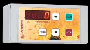
Holtkamp Electronics MICROTIMER                                                   techn. stand 04.2016                                                                                  4156_01.2021

                                                                                             Content
1    Legal information.......................................................................................................................................................................... 4
2    Warranty		           ................................................................................................................................................................................. 4
3    Safety notices............................................................................................................................................................................... 4
4    Notes on cleaning and maintenance.......................................................................................................................................... 4
5    Device specific data..................................................................................................................................................................... 4
6    General technical data................................................................................................................................................................. 4
7    Illustration of the device.............................................................................................................................................................. 5
8    Technical data and electrical connection..........................................................................................................................................5
9    Specifications .............................................................................................................................................................................. 6
10 Programming and statistic menu................................................................................................................................................ 7
     10.1      Statistic menu (bookkeeping).............................................................................................................................................. 8
     10.2      General programming menu (times)................................................................................................................................... 9
     10.3      Configuration menu............................................................................................................................................................. 9
11 Operation of the MICROTIMER.................................................................................................................................................. 12
Index				............................................................................................................................................................................... 14

Important: For safe and proper use, read the instructions for use and further product-related documents carefully and keep
it for later use!

For errors, technical errors, printing errors and incompleteness, we assume no liability.

                                                                                                -3-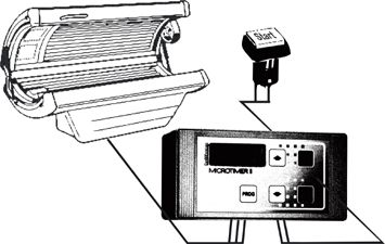
Holtkamp Electronics MICROTIMER                                        techn. stand 04.2016                                               4156_01.2021

1        Legal information                                                          2         Warranty
All rights reserved. No part of this manual may not be reproduced
or copied in any form without permission of Holtkamp Electronics                    The function of the device is guaranteed for 12 months from the date
GmbH. The rights for contained software in control and memory                       of sale (invoice date counts). The warranty is limited exclusively to
blocks are exclusively from the manufacturer. The reading and                       technical defects of the device, further claims can not be recognized.
copying of the program content is strictly prohibited.                              Furthermore, our General Terms and Conditions apply, as of April
The Holtkamp Electronics GmbH is not liable to the purchaser                        2020 - see also homepage: www.holtkamp.de. Any liability expi-
of this product or third parties for damages, losses, costs or ex-                  res in case of tampering with the device.
penses caused by the buyer or any third party due to accident,
misuse or unauthorized alterations, repairs or improvements.
The Holtkamp Electronics GmbH shall remain liable for any loss,
costs, disruptions or consequential damages that result from the
use of the control.
The technical data are up to date. Misprints, errors and modi-
fications excepted. Older manuals are no longer valid with the
publication of this manual.

3        Safety notices
The time control are built according to the prior art and the reco-                 Do provide for the safe and environmentally friendly disposal of
gnized safety rules.                                                                plastic parts and electronic replacement parts! The manufactu-
Nevertheless, its use threats to life and limb of the user or third                 rer is not liable for damage caused by improper use. The user
parties, or cause damage to the device or other equipment du-                       bears the risk. Intended use also includes compliance with the
ring use. Use the device only in perfect condition, and intended,                   operating instructions and compliance with the inspection and
safety and the risk of danger, in compliance with the instruction                   maintenance conditions.
manual! Do immediately eliminate particular disorders, which
may affect safety! Always keep the operating instructions directly
to the time control! Note, in addition to the user guide, the gene-
rally applicable legal and other mandatory regulations relevant to                            ATTENTION:
accident prevention and environmental protection!                                             The installation must be performed by authorized pers-
Perform no changes and/or modifications to the time control wi-                               onnel!
thout approval of the manufacturer! Spare parts must meet the                                 Therefore, make sure that the installation is carried out
requirements specified by the manufacturer. This is guaranteed                                by an electronics specialist! Since this is a stationary
only for original spare parts. Do observe the in the user manual                              device with main-side fixed connection, a circuit brea-
specified or prescribed deadlines for recurring maintenance in-                               ker must be installed on the installation side!
tervals!

4        Notes on cleaning and maintenance
The plastic housing can be cleaned with a damp cloth and wa-
ter-soluble cleaning agent. Never use thinner, gasoline, acetone
or abrasive cleaning agents.

5        Device specific data
 Software version
 (The display appears it for a short time, 2 seconds after activate)

 Serial-Number (written on the type plate)
 Commission
 Trader

6        General technical data
The Holtkamp MICROTIMER is particularly designed for the per-                       The MICROTIMER is connection and installation-compatibly to
sonnel-served timing of sun beds. It was revised fundamentally                      the MICROTIMER of the 1. Generation. It is developed compac-
and offers the following innovations                                                tly, transformer, relay and electronics is completely on a printed
    ● Safety disconnection (110%-emergency stop timer) with                         circuit board.
      specially relays: If the microprocessor should fail or should
      stick the main relay, the sun bed is switched off safely.
    ● Improved and clearer menu guidance.

                                                                                  -4-
Holtkamp Electronics MICROTIMER techn. stand 04.2016 4156_01.2021
Single device Installed equipment
Installation frame
MICROTIMER 82502 MICROTIMER 8150
Material casing Polycarbonate plastic
Material front panel Plastic ABS
Color casing Light-grey RAL 7035
Color foil keyboard Light-grey, Yellow, Red, Green
Dimension mm:
a) Casing h 80 x w 160 x d 62
b) framework size 6er h 250 x w 390 4er h 180 x w 390
c) clipping of Installed
h 70 x w 150 x d45
equipment
Installation depth 75 mm min. 50 mm
Electrical Data* 230 V or 24 V, 50 Hz 230 V or 24 V, 50 Hz
Switched power 6,3 A by cos phi = 1 6,3 A by cos phi = 1
Power consumption 2,3 VA per single device 2,3 VA per single device
* Please indicate when ordering! Technical changes as well as technical advancements reserved.2
7 Illustration of the device
1 2 3
1 red display with four digits
2 UP button
3 START button
4 PROG button
5 DOWN button
6 STOP button
4 5 6
8 Technical data and electrical connection
Connection only considering the VDE regulations of a
specialist to accomplish leave!
Back of the MICROTIMER printed circuit board:
remote/clean
PE N L over-run main
-5-Holtkamp Electronics MICROTIMER techn. stand 04.2016 4156_01.2021
Connections
a) Version 230 V (standard) Over run: potential free contacts of follow-up relay, switched pow-
PE: Earth wire er max. 250 V / 6,3 A by cos phi = 1p
N und L: 230 VAC / 50-60 Hz supply of voltage (ca. 3 VA)
b) Version 24 V (special equipment) If with the relay contacts the contactors are addressed,
PE: Earth wire the contactor coils with a RC combination must be
bridged. Otherwise when switching off the sparks
N and L: 24 VAC / 50-60 Hz supply of voltage (ca. 3 VA)
at the relay contacts can develop, which can lead to loss
c) Generally (230 V and 24 V) the equipment!
Main: potential free contacts of main relay, switched power
max. 250 V / 6,3 A by cos phi = 1 Remote/cleaning: Connection for floating remote start and/or
cleaning button (this connection included
harmless safe voltage leads!)
8.1 Electrical connection
The electrical connection can only be carried out by the local
VDE regulations. With a permanent connection, an all pole mains
separator with at least 3 mm contact gap must be used. Before
starting the electric circuit must be disconnected. Shut down the
mains input by activating the separator switch, remove the fuse
or release the main safety fuse. Mains and low voltage cable
must be spaced apart. Low voltage cables should be generally
spaced as screened cables.
ATTENTION:
The installation must be performed by authorized pers-
onnel!
Therefore, make sure that the installation is carried out
by an electronics specialist! Since this is a stationary
device with main-side fixed connection, a circuit brea- Control cable and remote start connection have to be
kept away from each other!
ker must be installed on the installation side!
9 Specifications
MICROTIMER 8150 MICROTIMER 8250
Single device - in the plastic housing -
Installed equipment for 4/6er framework -
controls 1 device
Pre-run time
Main time (1 min. – 999 min.)
Over-run time
Maximum time
LED display (real time indication)
Programming overr foil keyboards
electronic customer counter
electronic operating hour counter
electronic service hour counter
Remote start
Enforcement remote start
Main time change lock
Timer lock
Switching to memory mode
Power failure memory
3 codes for access authorization
-6-Holtkamp Electronics MICROTIMER techn. stand 04.2016 4156_01.2021
MICROTIMER 8150 MICROTIMER 8250
Mounting kit -
Connection possibility for cleaning button
Safety shutdown 110%
4er framework -
6er framework -
Blind access cover
-
(for blank field framework)
standard equipment
10 Programming and statistic menu
There are altogether 3 menus, which can be protected with ac-
cess codes from unauthorized access:
With the distribution are programmed all 3 access codes on
"0", with it all menus are freely accessible.
● Statistic menu (access code 3, 2 or 1 necessarily): Here are
the customer and the operation hour counters etc. If the access code 3 to “0” programmed, this code
with1 and 2 is always out of operation (even if these are
● General programming menu (access code 3 or 2 neces-
not programmed on "0")! If code 2 on "0" program-
sarily): Here the times are programmed (time delay, main
med, the code is 1 out of operation.
time etc.)
● Configuration menu (access code 3 necessarily):
Here main read functions of the MICROTIMERS are speci-
fied. Configuration menu
Gen. programming menu
Statistic menu ● 3 Code numbers
● Pre-run time
● Special functions
● Main time
● Customer counter ● Maximum time
● Operating hours counter ● Run-out time
● Service hours counter ● Service intervals
Access authority with
Code no. 3
Access authority with
Code no. 2 or 3
Access authority with
Code no. 1 or 2 or 3
If access code 2 is programmed, it is possible to delete the coun- For all menus applies:
ter on the Menu1 only under the input with the access code 2
(or access code 3). With this personnel can read off the coun- With the programming button "PROG" the menus are reached:
ters, but not delete. ● after a unique operation of the Statistic menu
● after a twice operation of the General programming menu
Following to uncontrolled programming can have not
● after a threefold operation of the Configuration menu
desired functions. In particular, the unplanned input of
the access codes entails a blocking of the programming ● appears after a four times operation again the Statistic
menu, so that does not arrive anymore into the menu, menu
with- out knowing the entered access code.
-7-Holtkamp Electronics MICROTIMER techn. stand 04.2016 4156_01.2021
With the START button are the menu options of the current selec-
ted menu paged through. A short operated is pages forward, a
long is pages (approx. 0,3 seconds) backward. From the current
selected menu are the menu point number and the programming
value are in the change indicatedt.
Automatic repeat function: If the START button is pressed lon- With the STOP button the menus will leave. It happens also, if for
ger than 850 ms, the menu options are scrolled automatically. a while no more button is pressed (automatic menu completion).
Was the button in advance pressed for a long time backwards,
then the Autorepeat taken place backwards.
With the UP button are increased the indicated value of the cur-
After the completion of the menus the START and STOP
button, the UP and DOWN button still all blocked during
rent menu option in the configuration menu and in the program- 2 seconds long this is in order to prevent inadvertent star-
ming menu, reduced it with the DOWN button. If these two but- ting/stopping/changing of the main time.
tons are pressed at the same time in the Statistic menu, the
indicated value is deleted.
10.1 Statistic menu (bookkeeping)
The appeal of this menu takes place through pressures the UP and DOWN button are pressed at the same time, the indica-
PROG button. ted value is deleted. Only one pressed DOWN button, the mode
With the START button the menu options are paged through. A of operation and the software-version number are indicated
manipulation for a short time leafs forward, a longer backwards (mode of operation is always 6, left in the display).
In the shown rectangles the symbol indicated is specified in the
display, the announcement effected witch can be programmed
change with the value:
Enter access code 1, 2 or 3 Daily customer counter
1Cd
- This menu option appears only, if code
1, 2 and 3 to a value is unequally "0"
bC-
(C = Customers)
- This menu option appears only, if in the
programmed and were entered none configuration menu the menu option of
of these codes, sees configuration "daily counters" is activated.).
menu! - Continues to count always around 1, if
- With code 1 the menu can be only dele- main time is started. See also option
ted. Exception: The daily counters can "oS1" in the configuration menu
be deleted also with code 1
Daily operating hour counter Total customers counter
bbE-
- This menu option appears only, if in the
configuration menu the menu option of
bC
(C = Customers)
- Continues to count always around 1, if
"daily counters" is activated. the main time is started. See also option
- Counts during the cyclic duration of the oS1 in the configuration menu.
main relay (max. 9999 Std.)
- If is pressed and held the up button,
instead of the hour number the minutes
and seconds of the started hour are in-
dicated, separated with a decimal point
(max.59.59).
Total operation hour counter Service hour counter 1
bbE
- Counts during the cyclic duration of the
main relay (max. 9999 Std.)
b51
- This menu option appears only, if gene-
rally programming the menu option
- If is pressed and held the up button, "service interval of 1" is unequally to "0"
instead of the hour number the minutes programmed to a value.
and seconds of the started hour are in- - Counts parallel to the operation hour
dicated, separated with a decimal point counter. If a given value is reached (see
(max.59.59). to service interval 1 generally program-
ming menu), flashes in the retirement
of the MICROTIMERS, as well as if this
menu option is appeal for, the decimal
point of the display unit place, with
which the service staff is requested for
maintenance of the sun bed and reset-
ting the service hour counter
-8-Holtkamp Electronics MICROTIMER techn. stand 04.2016 4156_01.2021
Service hour counter 2 Service hour counter 3
b52
- see Service hour counter 1
b52
- see Service hour counter 1
10.2 General programming menu (times)
The appeal of this menu takes place through (if necessary 2 A manipulation for a short time leafs forward, a longer backwards.
times) pressures of the PROG button. With the UP button the indicated value increased, it reduced with
With the START button the menu options are paged through the DOWN button.
In the shown rectangles the symbol is specified and indicated
in the display, the announcement effected the change with the
value which can be programmed:
Enter access code 2 or 3 Pre-run time
2Cd
- This menu option appears only, if code
2 and 3 to a value unequally "0" is pro-
u
- This menu option appears only, if in the
configuration menu is adjusted the opti-
grammed and were entered none of the- on "oFS2" to "0".
se codes, see configuration menu! - Signal delay: 0:00 to 9:59 min in second
steps adjustable. If adjusted to "0" no
lead the time.
Main time Maximum time border
h
- Tanning time, from 0:01 to the maximum
time border adjustable (to formatting
oh
- Upper limit for the main time, if the tan-
ning were begun with the START button
the announcement see configuration and afterwards with UP and DOWN but-
menu, option oSE and oSA). ton the given main time is changed (or
if the main time with repeated manipu-
lation of the START button is increa-
sed.
If the maximum time border is adjusted to “0", then it is out of (to formatting the announcement see configuration menu, option
operation! "oSE" and "oSA".)
Here the maximally permitted tanning time must be en-
tered, those the sun bed manufacturer indicates!!!
Ventilator Run-out time Service interval 1
able
n
- 0:00 to 9:59 min. in second steps adjust-
Si1 - If service hour counter 1 in the statistic
menu present achieved the value given
here, the case of service occurred.
Adjustable of "0" until "9999" hours in
hour steps (if on "0", then out of operati-
on)
Service interval 2 … 3
- analogue Serviceinterval 1
10.3 Configuration menu
The reach it, the menu takes place through (if necessary 3 times) A manipulation for a short time leafs forward, a longer backwards.
pressure the PROG button. With the UP button the indicated value increased, it reduced with
With the START button the menu options are paged through. the DOWN button.
In the shown rectangles the symbol is specified and indicated
in the display, the announcement effected the change with the
value which can be programmed:
Enter access code 3 Option "1-second pulse"
3Cd
- This menu option appears only, if the
code to a value unequally "0" is prog-
oSE
(adjustable to "1" or "0" )
- 1: Expiration of main time course is ac-
rammed and were entered none of these celerated around factor 60 (1-second
codes, see also this menu under "Cd3". pulse)
- 0: Expiration of main time course nor-
mally (minutes pulse)
- Dependently from this option the main
time is shoed and the display either as
amount of minute or as amount of se-
cond.
- Independently of this attitude all opera-
ting and service hour counter always
count in hour/minutes (see statistics
menu)
-9-Holtkamp Electronics MICROTIMER techn. stand 04.2016 4156_01.2021
Option "Clock format indicate" Option „Memory allows"
oUF
(adjustable to "1" or "0")
- 1: Indicate to the main time effected in
oSP
(adjustable to "1" or "0")
- 1: repeated tapping on the START but-
the clock format: 0:00 to 9:59 hours mi- ton adds the adjusted main time o (that
nutes (if option oSE = 0) and/or minu- is possible only during the time delay
te/seconds (if "oSE" = 1) and the first minute of the main time).
- 0: Indicate to the main time effected in The time delay can be broken off only
the simply format: 0 to 999 minutes by remote START button.
(if option "oSE" = 0) and/or seconds - 0: main time is loaded only once, se-
(if "oSE" = 1). cond operation of the START button ter-
minates the time delay and starts the
main time immediately
Option "Remote start" Option "Enforcement remote start"
oFS
(adjustable to "1" or "0")
- 1: With operated of the remote start
oFS2
(adjustable to "1" or "0")
- 1: Definition by cases:
button: Abort of the time delay and a) Option "oFS" is likewise adjusted to
start of the main time. "1": the main time starts only after ope-
- 0: main time starts either at expiration of rated of the remote start button. Time
the time delay or with operated of delay and start by START button at the
START button at the equipment. equipment are out of operation.
After the start the display shows so long
“FS” alternating with the main time, un-
til the remote start button is pressed.
b) Option "oFS" is adjusted to "0":
the main time starts immediately after
operated of the START button at the
equipment.
- 0: Sun bed can be started also by
START button, the time delay thereby is
broken off
Option "Cleaning time” Option "HQL time“
oPu
(adjustable to "1" or "0")
- 1: after use of the sun bed the start of
oHOL
(adjustable to "1" or "0")
- 1: The main time can be loaded with the
a further main time is blocked until tho- START button during the after cooling
se was operated cleaning button. In the time but no started (cooling phase for
display flashing "PU" appears. HQL emitters). At course of the time de-
- 0: after use of the sun bed a further, lay or after remote start the possibly still
main time can be unconditionally running off after cooling time is indicated
started. in the display in change with the main
time, the main time starts only at their
expiration.
- 0: The sun bed can be already started
again during the after cooling time.
Option "Memory for power failure" Option "Released the up and down
onAS
(adjustable to "1" or "0")
- 1: If is a mains failure the timer returns
oAA
counting button after start"
(adjustable to "1" or "0")
to operating condition: - 1: the main time can be changed after
- If the failure during the time delay, then the start for a while
the time delay is deleted and the main - 0: the main time cannot be changed af-
time can be started by operated of the ter the start
START button or remote start button.
- If the failure during the main time, the
main time can be continued by opera-
ted of START button or Remote start
button.
- If the failure during the Run-out time,
then the Run-out time starts automati-
cally and the follow-up relay tightens.
Generally applied: With the STOP but-
ton the enterprise can be broken off.
- 0: started delay, main and after cooling
time go lost with the mains failure.
- 10 -Holtkamp Electronics MICROTIMER techn. stand 04.2016 4156_01.2021
Option "Pre-run time stop” Option "Follow-up relay“
oUS
- This point have only an implication, if a
Pre-run time is adjusted and the points
oUr
(adjustable to "1" or "0")
- 1: after cooling relay switches on at the
„oSP“ = 0 and „oAA“ = 1 are adjusted beginning of the time delay and is cont-
in the general programming menu. inuous switched on to the end of the
In that case the Pre-run time runs at the after cooling time
first not after the start. With the UP and - 0: after cooling relay switches on at the
DOWN button you can change the main beginning of the time delay and is cont-
time. The Pre-run time begins with repe- inuous switched on to the end of the
ated exertion of the START button. after cooling time
If you push the START button a third
once, the Pre-run time is broken off and
the main time starts now.
Option "Customers counter counts Option "Daily counter"
o51
when saving only 1 time"
(adjustable to "1" or "0")
otA
(adjustable to "1" or "0")
- 1: In the statistic menu some counter
- 1: If the main time is added by a repe- appear double (daily and total counter
ated exertion of the START button (see parallel. The daily counter can be read
option "oSP"), the customer counter off and deleted daily).
(see statistic menu) counts only 1 time. - 0: In the statistic menu each only coun-
- 0: If the main time is added by a repea- ter appears simple (total counter).
ted operated of the START button, the
customer counter continues counting
with each addition by 1
Access code 1 (for Statistic menu) Access code 2 (for General program-
Cd1
- Adjustable of "0”... “9999".
If a value is adjusted here between "1”…
Cd2
ming menu and statistic menu)
- Adjustable of "0”... “9999".
“9999", the counters of the statistic If a value is adjusted here between "1”...
menu only can be appeal for and viewed “9999", the general programming menu
(not to be deleted, with exception of the only can be appeal for, if this code is
daily counter), if this code is entered entered there.
there. (Alternatively also the access code 3
(Alternatively also the access codes 2 or can be entered there!).
3 can be entered there!). This code releases the deletion of the
counters in the statistic menu.
Access code 3 (Configuration menu,
Cd3
general programming menu and stati-
stic menu)
- Adjustable of "0”... “9999".
If a value s adjusted here between "1”...
“9999", the configuration menu only can
be appeal for, if this code is entered the-
re. This code releases the general pro-
gramming menu as well as the deletion
of the counters in the statistic menu
- 11 -Holtkamp Electronics MICROTIMER techn. stand 04.2016 4156_01.2021
11 Operation of the MICROTIMER
Course of a tanning ● By press of the START button timing with the programmed
The operational sequence described here can be changed by current values is started. Delay and main time appear in
some attitudes in the configuration menu. The following example the display (time delay only if does not program on "0").
works with the attitudes, which are programmed by the factory
with the distribution of the MICROTIMERS:
Example (START button pressed):
h 5.
Short indicate: = main time 5 minutes
u 2.00
After that: = backwards running Pre-run time 2:00 minutes
After expiration of the
Pre-run time: h 5. = backwards running main time, decimal point flashes
main time: n 3.00
After expiration of the = backwards running Run-out time 3:00 minutes
● With the UP and/or DOWN button can be changed the pre- ● The operating of the STOP button breaks lead and main
programmed main time for the current tanning (only during time off, not however the after cooling phase.
the Pre-run time and the first minute of the main time).
Happens during the Pre-run time, the main time is short-
ly indicated. This function can be blocked in the configurati
on menu!
● The Pre-run time can be broken off by renewed pressing of
the START button or by the remote start button. This func-
tion can be blocked in the configuration menu!
12 By malfunctions
The MICROTIMER shows error messages on the display during
faulty operation and at further opportunities. The error messages
are indicated usually 3 seconds long flashing:
Error code Possible causes
EEPROM memory of the device defectively, errors with reading
E03
EEPROM conductive strips or other construction units defectively
EEPROM memory of the device defectively, run time errors with writing,
E04
EEPROM conductive strips or other construction units defectively
This function is blocked, because the access code necessary for it was not entered,
E47
or a wrong code was entered!
- 12 -Holtkamp Electronics MICROTIMER techn. stand 04.2016 4156_01.2021
- 13 -Holtkamp Electronics MICROTIMER techn. stand 04.2016 4156_01.2021
Index
Symbole O
1-second pulse 9 Operating hour counter, daily 8
Operation 12
A Operation hour counter, total 8
Access code 1 11
P
Access code 1, 2 or 3 8
Access code 2 11 Pre-run time 9
Access code 2 or 3 9 Pre-run time stop 11
Access code 3 9, 11 Programming 7
C R
Cleaning 4 Released the up and down counting button after start 10
Cleaning time 10 Remote start 10
Clock format indicate 10
Configuration menu 9 S
Connections 6 Safety notices 4
Content 3 Service hour counter 1 8
Course of a tanning 12 Service hour counter 2 9
Customer counter, daily 8 Service hour counter 3 9
Customers counter 11 Service interval 1 9
Customers counter, total 8 Service interval 2 … 3 9
Specifications 6
D
Specific data 4
Daily counter 11 Statistic menu 8
Daily customer counter 8 Statistic Menu 7
Daily operating hour counter 8
T
E
Technical data 5
Electrical connection 5, 6 Total customers counter 8
Enforcement remote start 10 Total operation hour counter 8
Enter access code 8
Enter access code 2 or 3 9 V
Enter access code 3 9 Ventilator Run-out time 9
Error code 12
W
F
Warranty 4
Follow-up relay 11
G
General programming menu 9
General technical data 4
H
HQL time 10
I
Illustration of the device 5
L
Legal information 4
M
Maintenance 4
Main time 9
Malfunctions 12
Maximum time border 9
Memory allows 10
Memory for power failure 10
- 14 -Holtkamp Electronics MICROTIMER techn. stand 04.2016 4156_01.2021
- 15 -For technical information during our business hours:
Monday - Thursday 8.00 a.m. - 16.00 p.m. and Friday 8.00 a.m. - 13.00 p.m. choose:
+49 541 97120-0
or visit our homepage:
www.holtkamp.de
Technical Stand 09.2019 / We reserve the right to technical changes in the production and technical developments.
4156_01.2021
Südstraße 40, D-49084 Osnabrück
Phone: +49 541 97120-0
info@holtkamp.deYou can also read