Operating and Assembly Instructions Incremental Hollow Shaft Encoder FGH 6
←
→
Page content transcription
If your browser does not render page correctly, please read the page content below
English

 Operating and Assembly Instructions
 Incremental Hollow Shaft Encoder FGH 6

 Read the operating and assembly instructions prior to assembly,
 starting installation and handling!
 Keep for future reference!

Translation of the original Operating and Assembly Instructions   FGH6_MANUAL-en_R14(2021-01-28)ID77280.docx
ID 77280

Incremental Hollow Shaft Encoder FGH 6

Trademark
Brand names and product names are trademarks or registered trademarks of their respective owner.
Protected trademarks bearing a ™ or ® symbol are not always depicted as such in the manual.
However, the statutory rights of the respective owners remain unaffected.

Manufacturer / publisher
Johannes Hubner
Fabrik elektrischer Maschinen GmbH
Siemensstraße 7
35394 Giessen
Germany
Phone:                        +49 641 7969 0
Fax:                          +49 641 73645
E-Mail:                       info@huebner-giessen.com
Internet:                     www.huebner-giessen.com

The manual has been drawn up with the utmost care and attention. Nevertheless, we cannot exclude
the possibility of errors in form and content. It is strictly forbidden to reproduce this publication or parts
of this publication in any form or by any means without the prior written permission of Johannes
Hubner Fabrik elektrischer Maschinen GmbH.
Subject to errors and changes due to technical improvements.

Copyright © Johannes Hubner Fabrik elektrischer Maschinen GmbH.
All rights reserved.

2                                                                      FGH6_MANUAL-en_R14(2021-01-28)ID77280.docx
Incremental Hollow Shaft Encoder FGH 6

Table of contents

1 General...................................................................................................................................... 5
    1.1   Information about the operating and assembly instructions ..................................................................5
    1.2   Scope of delivery ....................................................................................................................................5
    1.3   Explanation of symbols ..........................................................................................................................5
    1.4   Disclaimer...............................................................................................................................................6
    1.5   Copyright ................................................................................................................................................6
    1.6   Guarantee terms ....................................................................................................................................6
    1.7   Customer service ...................................................................................................................................6

2 Safety ........................................................................................................................................ 6
    2.1   Responsibility of the owner ....................................................................................................................6
    2.2   Intended use ..........................................................................................................................................6
    2.3   Non- intended use ..................................................................................................................................7
    2.4   Personal protective equipment ..............................................................................................................7
    2.5   Personnel ...............................................................................................................................................7
    2.6   Special dangers ......................................................................................................................................7
      2.6.1       Electrical current .........................................................................................................................7
      2.6.2       Rotating shafts ............................................................................................................................7
      2.6.3       Safeguarding against restart ....................................................................................................7
3 Technical Data .......................................................................................................................... 8
    3.1   Type plate...............................................................................................................................................8
    3.2   Electrical and mechanical data ...............................................................................................................9
    3.3   Type code............................................................................................................................................ 11

4 Transport, packaging and storage .........................................................................................12
    4.1   Safety instructions for transport .......................................................................................................... 12
    4.2   Incoming goods inspection.................................................................................................................. 12
    4.3   Packaging / (disposal) ......................................................................................................................... 12
    4.4   Storage of packages (devices) ........................................................................................................... 12

5 Installation and commissioning .............................................................................................12
    5.1   Safety instructions ............................................................................................................................... 12
    5.2   Mounting of the hollow shaft encoder (mechanically) ......................................................................... 13
      5.2.1 Assembly instruction for hollow shaft devices .................................................................... 13
      5.2.2 Assembly of a hollow shaft encoder FGH 6 and additionally a further encoder in
      construction type B5 onto the NDE of the FGH 6 ............................................................................ 14
    5.3   Connecting the hollow shaft encoder .................................................................................................. 15
      5.3.1       Connections ............................................................................................................................. 15
      5.3.3       Technical notes........................................................................................................................ 16
6 Disassembly ............................................................................................................................16
    6.1   Safety instructions ............................................................................................................................... 16
    6.2   Disassembly of the encoder ................................................................................................................ 16

7 Faults .......................................................................................................................................17
    7.1   Faults table .......................................................................................................................................... 17

8 Testing .....................................................................................................................................18

3                                                                                                FGH6_MANUAL-en_R14(2021-01-28)ID77280.docx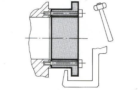
Incremental Hollow Shaft Encoder FGH 6

    8.1   Safety instructions ............................................................................................................................... 18
    8.2   Maintenance information ..................................................................................................................... 18
    8.3   Quality control plan ............................................................................................................................. 18

9 Disposal ...................................................................................................................................18
    9.1   Disposal procedure ............................................................................................................................. 18

10 Dimension drawings ...............................................................................................................19
11 Connection Diagrams .............................................................................................................32
12 Mounting instructions for coupling .......................................................................................34

4                                                                                             FGH6_MANUAL-en_R14(2021-01-28)ID77280.docx
Incremental Hollow Shaft Encoder FGH 6
1 General
1.1 Information about the operating and assembly instructions
This operating manual provides important instructions for working with the device. It must be carefully
read prior to starting all tasks, and the instructions contained herein must be followed.
In addition, applicable local regulations for the prevention of industrial accidents and general safety
regulations must be complied with.
1.2 Scope of delivery
Incremental Hollow Shaft Encoder FGH 6, operating and assembly instructions.
1.3 Explanation of symbols
Warnings are indicated by symbols in this operating manual. The warnings are introduced by signal
words that express the scope of the hazard.
The warnings must be strictly heeded; you must act prudently to prevent accidents, personal injury, and
property damage.
WARNING!
Indicates a possible dangerous situation that can result in death or serious injury if it
is not avoided.
CAUTION!
Indicates a possible dangerous situation that can result in minor injury if it is not
avoided.
CAUTION!
Indicates a possible dangerous situation that can result in material damage if it is not
avoided.
NOTES!
Indicates useful tips and recommendations as well as information for efficient and
trouble-free operation.
NOTES!
Mounting and disassembly by means of a hammer or similar tools is not permitted
(warranty void).
DANGER!
Life threatening danger due to electric shock!
Indicates life-threatening situation due to electric shock. If the safety instructions are
not complied with there is danger of serious injury or death. The work that must be
executed should only be performed by a qualified electrician.
5 FGH6_MANUAL-en_R14(2021-01-28)ID77280.docxIncremental Hollow Shaft Encoder FGH 6
1.4 Disclaimer
All information and instructions in this operating manual have been provided under due consideration of
applicable guidelines, as well as our many years of experience.
The manufacturer assumes no liability for damages due to:
Failure to follow the instructions in the manual
Non-intended use
Deployment of untrained personnel
Opening of the device or conversions of the device
In all other aspects the obligations agreed in the delivery contract as well as the delivery conditions of
the manufacturer apply.
1.5 Copyright
NOTE!
Content information, text, drawings, graphics, and other representations are protected
by copyright and are subject to commercial property rights.
It is strictly forbidden to make copies of any kind or by any means for any purpose other
than in conjunction with using the device without the prior written agreement of the
manufacturer. Any copyright infringements will be prosecuted
1.6 Guarantee terms
The guarantee terms are provided in the manufacturer´s terms and conditions.
1.7 Customer service
For technical information personnel are available that can be reached per telephone, fax, email, or via
the Internet, see manufacturer´s address on page 2.
2 Safety
This section provides an overview of all the important safety aspects that ensure
protection of personnel, as well as safe and trouble-free device operation.
If these safety instructions are not complied with significant hazard can occur.
2.1 Responsibility of the owner
The device is used in commercial applications. Consequently the owner of the device is subject to the
legal occupational safety obligations and subject to the safety, accident prevention and environmental
protection regulations that are applicable for the device´s area of implementation.
2.2 Intended use
The device has been designed and constructed exclusively for the intended use described here.
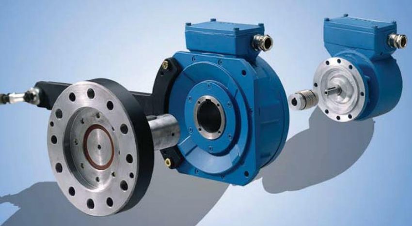
Series FGH 6 incremental hollow-shaft encoders are used for measurement of rotations, for instance of
electrical and mechanical drives and shafts.
Claims of any type due to damage arising from non-intended use are excluded; the owner bears sole
responsibility for non-intended use.
6 FGH6_MANUAL-en_R14(2021-01-28)ID77280.docxIncremental Hollow Shaft Encoder FGH 6
2.3 Non- intended use
The device may not be used in explosion-threatened areas.
On the device no other mechanical load may be exercised except his dead weight and the oscillations
without fail appearing during the company and pushes.
Examples of inadmissible mechanical charges (incomplete listing):
Connection of transport or lifting means in the device, e.g., load hook for raising of an engine.
Connection of packaging parts in the device, e.g., instep belts, tarpaulin, etc.
Use of the device as a step, e.g., for going up of a person on an engine.
2.4 Personal protective equipment
For tasks such as assembly, disassembly or commissioning the use of personal protective equipment
such as safety footwear and protective work clothing is required.
The regulations specified by the owner and that are locally specified apply.
2.5 Personnel
Only skilled technical staff is allowed to perform installation, mounting, disassembly and
commissioning work.
2.6 Special dangers
Residual risks that have been determined based on a risk analysis are cited below.
2.6.1 Electrical current
DANGER!
Life threatening danger due to electrical shock!
There is an imminent life-threatening hazard if live parts are touched. Damage to
insulation or to specific components can pose a life-threatening hazard.
Therefore:
Immediately switch off the device and have it repaired if there is damage to the
insulation of the power supply.
De-energize the electrical equipment and ensure that all components are connected,
for all tasks on the electrical equipment.
Keep moisture away from live parts. Moisture can cause short circuits.
2.6.2 Rotating shafts
WARNING!
Danger of injury due to rotating shafts!
Touching rotating shafts can cause serious injuries.
Therefore:
Do not reach into moving parts/shafts or handle moving parts/shafts during operation.
Do not open covers during operation. Prior to opening the covers ensure that all parts
have come to a standstill.
2.6.3 Safeguarding against restart
DANGER!
Life-threatening danger if restarted without authorization!
When correcting faults there is danger of the power supply being switched on without
authorization.
This poses a life-threatening hazard for persons in the danger zone.
Therefore:
Prior to starting work switch off the system and safeguard it from being switched on
again.
7 FGH6_MANUAL-en_R14(2021-01-28)ID77280.docxIncremental Hollow Shaft Encoder FGH 6
3 Technical Data
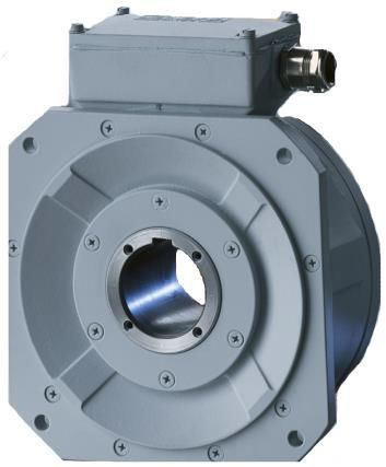
3.1 Type plate
Type plate example:
The type plate is located on the side of the housing and contains the following information:
Manufacturer, address
Type
CE-mark
Serial number (S/N)
Year of construction
Pulse rate
Degree of protection
Supply voltage
8 FGH6_MANUAL-en_R14(2021-01-28)ID77280.docxIncremental Hollow Shaft Encoder FGH 6
3.2 Electrical and mechanical data
Pulse rates Value
Preferred pulse rates
1024, 2000
(nickel disks)
Pulse rates available 512, 1000, 1200, 1800, 2048, 2500
Connection data
Supply voltage 12 … 30 V DC (Option: 5 VDC)
No load-current approx. 100 mA at 30 V (without Option)
Differential line-driver, resistant to sustained short-
Outputs
circuit, current limited, short-circuit.
Pulse height (HTL) approx. as supply voltage
Internal resistance 50 Ω per output
Pulse height (TTL) 5 V to RS 422
Slew rate 50 V / µs
Pulse duty factor 1:1±5%
to 50 KHz < 3 %
Square wave displacement 0°, 90°
to 150 KHz < 5 %
Max. frequency 0 to 100 kHz. (to 150 kHz on request)
Encoder temperature ranges
Standard 0°C … + 70°C
Special temperature -25°C … + 85°C
Special output voltage 5V (TTL)
Pulse height 5V, RS422 compatible (TIA/EIA-Standard)
Supply voltage 12 … 30 V DC
Protection class Sealing Mechanical Description Breakaway
DIN EN 60529 speed torque
IP 54 Special seal ≤ 4000 rpm Protection against approx. 30 to 50
dust and water Ncm
spray
IP 66 Radial shaft seal ≤ 1500 rpm Protection against approx. 60 Ncm
only drive side dust and water
spray
IP 66 Radial shaft seal ≤ 1100 rpm Protection against approx. 70 Ncm
both sides dust and water
spray
Weight Type K 6 kg
Type KK 6,8 kg
9 FGH6_MANUAL-en_R14(2021-01-28)ID77280.docxIncremental Hollow Shaft Encoder FGH 6
Signal outputs
Basic version (n = pulses/revolution).
One pulse channel (basic) with n direct square
wave pulses, corresponding to the segment
division and LED monitoring output. (optional
conditional).
Option 90
2nd pulse channel as basic version, bit with 90°
electrical phase shift.
Option N / N2
Marker pulse, mechanically fixed. One square
wave pulse per revolution.
Option G
Additional inverted output signals for basic and
90° channels, marker pulse plus LED check.
Option F
With 2 or 4 times as many pulses as basic
version, No direction of motion can be derived
from the multiple number of pulses
Option B Output
Fast and precise sensing of rotational direction L R
at each edge of the basic and 90° channels. cw 0 1 Option
Prerequisite: Option 90° ccw 1 0 B, B2
Still stand 0 0 Option B2
Option B2
As option B, but with standstill sensing.
Option V
Electronic pulse doubling of basic and 90°
channels by multiple evaluation.
Option L2
Power output up to 150 mA for basic channel,
90° channel and the corresponding inverted
signals.
Option J
Reduced rotational frequency modulation by
means of optically adjusted pulse disk
Option J50
Specially adjusted pulse disc.
Rotational vibration < 50 seconds of arc.
Option S
Electronic overspeed switch with 2 programmable
switching outputs, EGS4 version (see operating and
assembly instructions EGS 4).
10 FGH6_MANUAL-en_R14(2021-01-28)ID77280.docxIncremental Hollow Shaft Encoder FGH 6
3.3 Type code
90 G /50P
Incremental
Hollow Shaft Encoder
Synthetic bushing
Series
Connection
K: Terminal box
S: Industrial plug
R: 12 pole. round plug
C: 2 m connection cable
L: fiber optics- technic
2x connection = redundant Encoder
or Encoder with Option S
e.G.. KK = 2 terminal boxes
Pulses per revolution
Basic signal output
Basic channel 0° (A)
Pulse channel 90° (B)
Each with inverted signals
Reference pulse with
inverted signal
2 F: Option 2F
4 F: Option 4F
B: Option B
B2: Option B2
S: Option S EGS® 4 Technic 2nd terminal box
L2: Option L2
V: Option V
J: Option J and J50 can be combined with V
Drive shaft connection
P: keyway
S: pressure sleeve
C: taper
11 FGH6_MANUAL-en_R14(2021-01-28)ID77280.docxIncremental Hollow Shaft Encoder FGH 6
4 Transport, packaging and storage
4.1 Safety instructions for transport
CAUTION!
Improper transport can cause property damage!
4.2 Incoming goods inspection
Check delivery immediately upon receipt for completeness and possible transport damage.
Inform the forwarder directly on receipt of the goods about existing transport damages (prepare pictures
for evidence).
4.3 Packaging / (disposal)
The packaging is not taken back and must be disposed of in accordance with the respective statutory
regulations and local guidelines.
4.4 Storage of packages (devices)
Protect from moisture
Keep packed goods dry and protected against moisture.
Protect from heat
Protect packaged goods from heat over 40°C and direct sunlight.
If stored for longer periods (> 6 months) we recommend sealing the devices in foil, possibly with a
desiccant.
Attention:
Turn encoder shafts every 6 months 10 times to prevent a possible hardening of the
grease-filling of the ball bearings, which may lead to the destruction of the device.
5 Installation and commissioning
5.1 Safety instructions
Personnel
Installation and commissioning must be carried out by skilled technical staff only.
It is essential to observe safety instructions of chapter 2 before starting any tasks
(installation/testing) on the device.
12 FGH6_MANUAL-en_R14(2021-01-28)ID77280.docxIncremental Hollow Shaft Encoder FGH 6
5.2 Mounting of the hollow shaft encoder (mechanically)
Mounting and disassembly by means of a hammer or similar tools is not permitted (warranty void).
5.2.1 Assembly instruction for hollow shaft devices
1. Mount the adapter flange and align precisely with dial gauge; if necessary optimize the alignment
with ball pressure adjusting screws.
2. Secure the ball pressure screws with Loctite. Remove pressure screws that are not used, or
likewise secure them with a thread-lock lacquer. Max. tightening torque for M12 approximately 25
Nm; for M16 approximately 35 Nm.
1
Fig. 1 Fig. 2
The hollow shafts have tapped holes on both sides at the front. For removal use screws to attach the
mounting sleeve (Fig. 1), and the use a puller to draw off the unit. A suitable mounting sleeve is
recommended for each plant area (specify on ordering).
Remove hollow shaft encoders using mounting sleeve only.
NOTE!
The radial deviation of the shaft (Fig. 2 Pos. 1) should not exceed 0,05 mm.
3. Use feather keys in accordance with DIN 6885.
4. Mount the torque bracket/torque arm on the housing.
NOTE!
Comply with the information provided in the supplemental data sheet entitled
“Mounting Accuracy of hollow shaft encoders”.
5. Check the mounting position relative to the terminal box, adjust if necessary.
6. Push the device onto the shaft that has been lightly greased.
CAUTION!
Danger of damage to shaft and hollow shaft encoder if improperly handled.
Ensure that there are no hard impacts on hollow shaft and housing.
Use the mounting sleeve.
13 FGH6_MANUAL-en_R14(2021-01-28)ID77280.docxIncremental Hollow Shaft Encoder FGH 6
7. Secure the device with axial tightening plate and 4x M5 x 16-DIN 912 fastening screws.
8. Fastening Axial tightening disc with 4x M4 x 20-DIN 912 fastening screws on the adapter shaft.
9. Tighten the fastening screws on the link head of the torque bracket. Fix the nuts in place with
locknuts.
10. Check the attached torque brackets: The link rod must be easy to turn within the link head, and the
link heads should not tilt. If this instruction is not followed there is a danger of bearing damage.
11. Connect the cabling in the terminal box ( see chapter 12, connection diagrams).
5.2.2 Assembly of a hollow shaft encoder FGH 6 and additionally a further encoder in construction
type B5 onto the NDE of the FGH 6
Assembly with metal bellows coupling:
1. Mount the adapter shaft onto the motor shaft.
2. Put the coupling (metal bellows coupling) on adapter shaft extension and fix the encoder with
a set screw.
3. Put the hollow shaft encoder FGH 6 onto the shaft that has been lightly greased and fix with
suitable axial tightening disc and screw. Details see chapter 5.2.1.
4. Put the to be coupled encoder onto the B14 flange of the hollow shaft encoder FGH 6.
Put the shaft carefully in the coupling bore. (Attention: The bore in the B 14 flange must show in
the direction of the set screw). Slide the rear encoder up to the mechanical stop and tighten it
with suitable screws.
Tighten the rear set screw of the coupling through the access of the B14 flange.
Then close the access with a lock screw.
See dimension drawing HM 14 M 108191.
14 FGH6_MANUAL-en_R14(2021-01-28)ID77280.docxIncremental Hollow Shaft Encoder FGH 6
5.3 Connecting the hollow shaft encoder
5.3.1 Connections
Cable glands are closed with a stopper to protect the devices on transport and storage.
Cable connections:
Have to be executed according to the encoder type.
Connection diagrams have to be considered!
Use of connection cables with diameter of min. 14 mm – max. 15 mm is essential to ensure the protection
class. Cable outlet should show preferably downwards.
5.3.2 Connection with integrated EGS® 4 technology in the second terminal box (option S)
The connections for the EGS® 4 technology are accommodated in the second terminal box of the hollow
shaft encoder.
Important instruction
For the function of the hollow shaft encoder, the voltage supply for the EGS® 4
technology in the second terminal box is also to be connected.
Wiring arrangement and shielding:
(EMC measurement)
The cable shielding must be connected on both sides.
The shield of the signal cable is directly connected to the housing of the encoder by the cable gland.
The common guidelines for EMI concerned cable routing have to be considered!
Sample Figure
Captive fastening
screws Terminal box
Print-wedges with
operating whip
Cable gland with
Terminal boxes seal plastic pins
Important instruction
The encoder can only be connected by competent persons.
Closing the terminal box cover
Check the seal of the terminal box cover, clean it if soiled. Then duly close the cover.
Cable must not be pinched
Attention with open terminal boxes.
Moisture should not get into the terminal box when connecting the cable.
15 FGH6_MANUAL-en_R14(2021-01-28)ID77280.docxIncremental Hollow Shaft Encoder FGH 6
5.3.3 Technical notes
Ambient temperature
The max. permissible ambient temperature depends on speed and protection class (shaft sealing)
of the encoder as well as on frequency, signal cable length and mounting situation. See chapter 3.2
Protection class
To comply with the protection class the signal cable diameter must be appropriate to the cable gland!
See chapter 5.3.1
6 Disassembly
6.1 Safety instructions
Personnel
Only trained, specialized personnel should perform any disassembly.
Attention: Observe safety instructions in chapter 2 before starting any tasks.
(Installation/maintenance/disassembly)
6.2 Disassembly of the encoder
Disassembly of the hollow shaft encoder has to be done in reverse sequence to chapter 5.2.
16 FGH6_MANUAL-en_R14(2021-01-28)ID77280.docxIncremental Hollow Shaft Encoder FGH 6
7 Faults
7.1 Faults table
Faults Possible cause Remedy
Soiled terminal box gasket or Clean terminal box gasket and
seal surfaces seal surfaces
Damaged terminal box gasket Replace terminal box gasket
Moisture in the terminal box Cable gland/blanking plug not Tighten cable gland/blanking
tightened plug
Unsuitable cable for cable gland Use suitable cable and cable
glands
Supply voltage not connected Connect supply voltage
No output signals
Connection cable reversed Wire correctly
Unsuitable cable Use data cable with conductors
arranged as twisted pairs and
common shield
Output signals subject to
Cable shield not connected Connect cable shield at both
interference
ends
Cable routing not EMC Observe applicable EMC
compliant guidelines when routing cables
Signal end stage overloaded Check pin assignment; observe
connection diagram
Do not assign unused outputs
Signal interruptions
Outputs short-circuited Do not connect outputs with
supply voltage or GND
No function at hollow shaft Supply voltage for the EGS® 4 Connect the power supply for
encoders with EGS® 4 technology not connected in the the EGS® 4 technology in the
technology in the second second terminal box. second terminal box.
terminal box (option S)
Contact Hübner-Service (page 2) if none of the remedies listed above provides a solution)!
17 FGH6_MANUAL-en_R14(2021-01-28)ID77280.docxIncremental Hollow Shaft Encoder FGH 6
8 Testing
8.1 Safety instructions
Personnel
Skilled technical staff only are permitted to inspect the device and its installation.
Observe the safety instructions contained in chapter 2 when inspecting or working on
the device.
8.2 Maintenance information
The device is maintenance free. However the following tests are recommended to ensure optimal,
problem free operation.
8.3 Quality control plan
Interval Inspections
Inspect the coupling for damage and ensure it is free of play
Ensure the fastening screws are properly tightened
Yearly
Ensure cable connections and connection terminals are
securely seated
Following approx 16 000 … 20 Check deep groove ball bearings are running smoothly and
000 hours of operation / higher listen for running noises
levels of continuous load
9 Disposal
9.1 Disposal procedure
The manufacturer is not obliged to take back electronics waste. The device consists of hybrid
components, and in part must be disposed of as special waste (electronic scrap) according to country-
specific legislation.
Local municipal authorities or specialized disposal companies provide information on environmentally
responsible disposal.
18 FGH6_MANUAL-en_R14(2021-01-28)ID77280.docxIncremental Hollow Shaft Encoder FGH 6
10 Dimension drawings
Special dimension drawings on request or see Internet.
KK Redundant version with
FGH 6 KK…/50P/B14 HM 14 M 107720
B14 flange
19 FGH6_MANUAL-en_R14(2021-01-28)ID77280.docxIncremental Hollow Shaft Encoder FGH 6 FGH 6 KK…/50P KK redundant version HM 14 M 107722 20 FGH6_MANUAL-en_R14(2021-01-28)ID77280.docx
Incremental Hollow Shaft Encoder FGH 6

 FGH 6 K…/50P/B14         B 14-flange                 HM 14 M 107721

21                                      FGH6_MANUAL-en_R14(2021-01-28)ID77280.docx
Incremental Hollow Shaft Encoder FGH 6

 FGH 6 K.../50P                                   HM 14 M 107723

22                                  FGH6_MANUAL-en_R14(2021-01-28)ID77280.docx
Incremental Hollow Shaft Encoder FGH 6

                         KK redundant version with
 FGH 6 KK…/50P/B14                                             HM 14 M 107733
                     B14-flange and integrated Option S

23                                            FGH6_MANUAL-en_R14(2021-01-28)ID77280.docx
Incremental Hollow Shaft Encoder FGH 6
KK redundant version with
FGH 6 KK…/50P HM 14 M 107744
integrated Option S
24 FGH6_MANUAL-en_R14(2021-01-28)ID77280.docxIncremental Hollow Shaft Encoder FGH 6
KK redundant version with
FGHI 6 KK…/40P/B14 HM 14 M 107731
B14 flange
25 FGH6_MANUAL-en_R14(2021-01-28)ID77280.docxIncremental Hollow Shaft Encoder FGH 6
FGH 6 K / (KK) with coupled KK redundant version or with
HM 14 M 108189
encoder: integrated option S
26 FGH6_MANUAL-en_R14(2021-01-28)ID77280.docxIncremental Hollow Shaft Encoder FGH 6
FGH 6 K / (KK) …/50P / B14 KK redundant version or with
HM 14 M 108203
with coupled encoders: integrated option S
27 FGH6_MANUAL-en_R14(2021-01-28)ID77280.docxIncremental Hollow Shaft Encoder FGH 6
FGH 6 K / (KK)…/50P / B14 KK redundant version or with
HM 00 M 55 128-1
with coupled encoder: integrated option S
28 FGH6_MANUAL-en_R14(2021-01-28)ID77280.docxIncremental Hollow Shaft Encoder FGH 6
FGH 6 K / (KK) KK redundant version or with
HM 15 M 108379
Construction type B3 / B14: integrated option S
29 FGH6_MANUAL-en_R14(2021-01-28)ID77280.docxIncremental Hollow Shaft Encoder FGH 6
FGH 6 K / (KK) …/ 50P / B14 KK Redundant version or with
HM 03 M 55 762
encoder with adapter shaft: integrated option S
30 FGH6_MANUAL-en_R14(2021-01-28)ID77280.docxIncremental Hollow Shaft Encoder FGH 6
FGH 6 K / (KK) …/ 50P / B14 KK redundant version or with
HM 14 M 108191
encoder with adapter shaft and assembly integrated option S
31 FGH6_MANUAL-en_R14(2021-01-28)ID77280.docxIncremental Hollow Shaft Encoder FGH 6 11 Connection Diagrams FGH 6 Standard Terminal box FGH 6 Standard Connection cable 32 FGH6_MANUAL-en_R14(2021-01-28)ID77280.docx
Incremental Hollow Shaft Encoder FGH 6

FGH 6   Standard               12 – pole plug

FGH 6    Standard                EMC industrial plug

33                        FGH6_MANUAL-en_R14(2021-01-28)ID77280.docx
Incremental Hollow Shaft Encoder FGH 6

12 Mounting instructions for coupling

34                                         FGH6_MANUAL-en_R14(2021-01-28)ID77280.docx
You can also read