USING ENCODERS WITH THE SIMPLEBGC 32 CONTROLLERS - LAST EDIT DATE: 21. JAN. 2019 VERSION: 0.15 - BASECAM ELECTRONICS
←
→
Page content transcription
If your browser does not render page correctly, please read the page content below
Using encoders with the
     SimpleBGC 32 controllers

Last edit date: 21. Jan. 2019
Version: 0.15
© Basecamelectronics® 2013-2019

                CONTENTS

                1. General information...............................................................3
                2. Installing encoders.................................................................5
                3. Testing encoders..................................................................10
                4. Calibrating encoders............................................................11
                5. FAQ........................................................................................ 15

© Basecamelectronics® 2013-2017                                                                                     2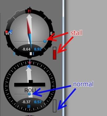
1. General information

   1. General information
   Using encoders with the SimpleBGC32 controller board gives the following advantages:
       1. Prevents motors from loosing synchronization and skipping steps.
       2. Provides full information about the position of a camera relative to a frame, that provides better
          model than 2nd IMU and makes use of 2nd IMU obsolete. This information extends the range of
          working positions and functionality of a gimbal.
       3. Can significantly decrease power consumption by using field-oriented control strategy to drive
          motors.
       4. Increases instant torque the same way.
       5. Provides possibility to get information about the camera balance and makes automatic balancing
          (with help of extra DC servomotors and moving counterweights).
       6. Allows to adjust camera position by hands.
       7.   Increase the precision of stabilization and the maximum speed of rotation that gimbal is able to
            compensate.
   Encoders give completely new feel of operating the system, and recommended to use in the professional-
   grade products.
   The stock firmware that comes with the regular SimpleBGC32 controllers does not support encoders. For
   using encoders, the special firmware is needed. You can get a trial or buy fully-functional encoder firmware
   here: http://www.basecamelectronics.com/encoders/
   Gimbal manufacturers, please contact us at info@basecamelectronics.com
   Note, that with this special firmware, all motors should have encoders installed! It is not possible to have
   one motor with encoder and other two without.

   List of supported encoders
   Below is the list of encoders supported by the SBGC32 gimbal controller. For the I2C_Drv and CAN_Drv
   modules, see their manuals to find models they support.
   AMT203 – absolute 12 bit capacitive technology, SPI interface
   AS5048A,B – absolute 14 bit on-axis magnetic, PWM, I2C or SPI interface
   MA3 – absolute on-axis magnetic. PWM 1kHz and 244Hz interfaces (10-12 bit resolution).
   Analog – potentiometer or any other type where analog output is proportional to the angle
   AS5600 – low-cost absolute 12 bit on-axis magnetic encoder with Analog, PWM 460Hz or I2C interface (for
   the I2C connection, address selection is not possible!)
   SBGC32_I2C_Drv or CAN_Drv expansion boards – acts as external motor driver combined with encoder
   interface, controlled over the I2C or CAN bus. More information can be found on our web page
   https://www.basecamelectronics.com.
   RLS Orbis (frw. ver.2.61+) – absolute off-axis (pass-throw) magnetic encoder. PWM 549Hz and SPI interfaces
   are supported.
   Zettlex IncOder (frw. ver. 2.68+, "Extended" and "Pro" boards only) – absolute off-axis high-precision encoder
   utilizing inductive technology, with the SPI interface and selectable 14..21 bit resolution.
   RLS AM4096 (frw. ver. 2.67b2+) – absolute 12 bit on-axis magnetic encoder with I2C interface.
   TLE5012B (frw. ver. 2.68+) - absolute 15 bit on-axis magnetic, SPI and PWM interfaces.
   Allegro A1335 (frw. ver. 2.68+) - absolute 12 bit on-axis magnetic, SPI and I2C interfaces.
   © Basecamelectronics® 2013-2017                                                                            3
1. General information

   Type of encoder can be selected during tuning process in the GUI.
   There is no big difference between 12bit and 14bit resolution, because encoders are not used in the
   closed-loop over speed and position, so high resolution is not strictly required. But a good linearity is
   important, especially if working together with the motors having big number of pole pairs.

   © Basecamelectronics® 2013-2017                                                                             4
2. Installing encoders
2. Installing encoders
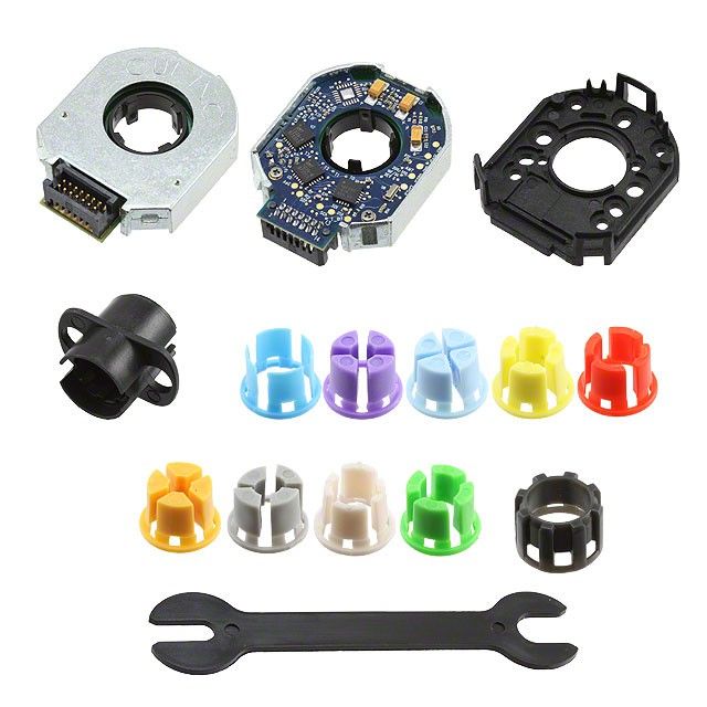
All on-axis magnetic encoders (like AS5048A,B) comes as an IC chip that should be soldered on the
custom-made PCB (our version is available here: https://www.basecamelectronics.com/as5048b/). This IC should
be placed below a specially polarized magnet, installed on the motor's shaft cup. Recommendations on
choosing magnet and positions tolerances can be found in a datasheet for the encoder.
For AS5048B connected to I2C bus, device address should be selected depending on motor where its
installed:
ROLL: 0x40 (A1=0, A2=0)
PITCH: 0X41 (A1=HIGH, A2=0)
YAW: 0X42 (A1=0, A2=HIGH)
Also you can assign address to axis later in the GUI.
The PWM connection option for the AS5048 gives less resolution (12bit compared to 14bit over I2С or SPI)
and can give less precision.
IMPORTANT NOTE: AS5048B is not compatible with the "High speed I2C" option!
AM4096 I2C encoder need to be configured for the I2C address. To do this, connect encoder to the main
controller, one encoder at a time. In the GUI, select encoder type "RLS AM4096 (I2C)" for the axis it relates
to, and select any unique address for it. The new "Encoder configuration tool" group will be shown in the
interface. Find an option "Set RLS AM4096 I2C address", select the same address from the provided set and
press the "ASSIGN" button. The new address will be assigned for this encoder and permanently stored in its
EEPROM. Disconnect configured encoder, connect next encoder and repeat the same steps, but assigning
different address to it.
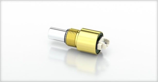
AMT203 encoder has a 8mm pass-throw hole and comes fully assembled with variety set of shaft adapters
and centering tool. When integrated inside motor, note that it is sensitive to electrical and magnetic fields.
Do not place it too close to stator windings or magnets of rotor!
© Basecamelectronics® 2013-2017 52. Installing encoders
MA3 magnetic encoder comes in 10 bit and 12 bit version (10bit has 1kHz refresh rate, 12bit has 244Hz
refresh rate). http://www.usdigital.com/products/encoders/absolute/rotary/shaft/MA3
Analog type may be a potentiometer, magnetic or other types with analog output, where voltage is linearly
proportional to the angle of rotation of the shaft. Analog encoders do not allow infinite 360 degree
rotation, because there are forbidden areas at both ends of its range. It is not recommended to use analog
type because of this limitation.
AS5600 magnetic encoder can be connected by its OUT pin, that is by default is configured as analog
output, and configured as “Analog” type in the GUI. Also, you can re-program it to the PWM output mode,
and choose “AS5600 PWM” type in the GUI. Note, that in the analog and PWM modes encoder does not
support full 360 degree of rotation, because it has hysteresis +-40 points near zero angle (1.75 degree).
HINT: For the PWM output mode, you have to program CONF register* by the I2C interface:
CONF = { WD(0) FTH(001) SF(11) }, { PWMF(10) OUTS(10) HYST(00) PM(00) } = {xx000111}, {10100000} = 0x07,
0xA0 - PWM at 460Hz, fastest response, no watchdog, no hysteresis, normal power mode.
After programming*, CONF should be written into the non-volatile memory. See AS5600 datasheet for details.
* If powered from 3.3V, 10uF buffer capacitor is required on VDD3V3 pin to ground to burn settings into OTP memory.
NOTE: starting from 2.60 firmware, AS5600 encoder will be automatically programmed into PWM mode, when
connected by the I2C interface first time and selected as "AS5600 (PWM)" in the GUI. Only 1 encoder at a time may be
connected by I2C. When programming is done, I2C lines may be disconnected. WARNING! Its impossible to use
encoder in analog mode after configuration is burned into OTP memory!
The best way is to connect it by the I2C interface – in this case it will support full 360 degree rotation.
IMPORTANT: only single AS5600 encoder may be present on I2C bus! To use more than one device of this
type, combine it with the I2C_Drv expansion modules, connect next two encoder to these modules and
using them as an external motor driver, connected to the main controller via common I2C bus. More
information on the I2C_Drv product page.
© Basecamelectronics® 2013-2017 62. Installing encoders
For the TLE512B SPI interface, link MOSI and MISO lines together and connect to the DATA line of the
encoder. It is required to add a series resistor 470 Ohm on the DATA line and 100 Ohm on the SCK line, as
recommended in the datasheet:
TLE512B MCU
MISO
470
DATA MOSI
100
SCK SCK
CSQ CS_x
Zettlex IncOder should be configured for the 5V supply, SPI interface and 14..21 bit resolution. For our
application, 14 bit is enough, but if more resolution is required, it can be increased up to 21 bit. Raw
encoder data can be read from our controller using Serial API (see CMD_REALTIME_DATA_CUSTOM
command). Encoder should be connected to the SPI port of MCU using special adapter
https://www.basecamelectronics.com/files/rs422_rs485_2spi.pdf
© Basecamelectronics® 2013-2017 72. Installing encoders
Connecting encoders to the SimpleBGC32 board
I2C encoders are connected parallel to the I2C IMU sensor for all board versions.
The "Pro" and "Extended" board versions have dedicated SPI/PWM inputs for the encoders. Check a
connection diagram on their product pages.
For the "Regular" or "Tiny" boards, pins for the SPI or PWM encoder connection are shared with the other
inputs. As the RC_ROLL input is occupied by the SPI bus, its alternative functions (Sum-PPM and serial) are
moved to the AUX3 input ("serial functions" are Spektrum, S-bus and SBGC Serial API interfaces).
NOTE: If the RC_ROLL input is not occupied by the SPI bus, starting from the firmware 2.60, you can return all serial
functions to it's origin: disable the check-box "Swap RC_SERIAL ↔UART2 ports" in the "Advanced" tab. But the Sum-
PPM input still stays on AUX3 in the encoder firmware.
SimpleBGC32 "Regular" or "Tiny" encoder connection
I2C GND
+5V GND
I2C encoder +5V
SDA
I2C
or
SBGC_I2C_Drv SCL SDA
SCL
GND
PWM GND
+5V
+5V
RC_ROLL
PWM_R
RC
RC_PITCH *
PWM_P
RC_YAW *
PWM_Y
FC_ROLL *
FC_PITCH
SPI GND
+5V
MISO AUX1 *
AUX
MOSI AUX2 *
SCK AUX3
CS_R
GND
CS_P
+3.3V
CS_Y
ADC
A1
Analog GND
A2
+3.3V
AS5048A A3
AS5048A OUT_R
AMT203
AMT203
(SPI) OUT_P
(SPI)
OUT_Y
* These pins acts as push-pull output in case of SPI connection.
Be careful and avoid short circuit or improper connection to other devices.
© Basecamelectronics® 2013-2017 82. Installing encoders
Tips on connection
• For a long SPI cable (more than 30cm) resistors on the SCK, MOSI line are strictly required! Use
33..60 Ohm resistor in the series on any output line (SCK, MOSI from the board side, MISO from the
encoder side). You can adjust their values more precisely by observing signal slope on the scope
on the receiver side. The signal should be sharp enough, without spikes caused by the reflections
(see picture below).
• The analog input is very sensitive to the EMI noise, so it's recommended to use a shielded cable in
case of long distance. But for big gimbals, its better to choose different type of encoder.
• For all PWM encoder types, it's better to setup them such way, that zero-crossing point (where raw
data crosses zero) is located far away from the normal working angles, because near this point
PWM signal can rapidly jitter between 0% and 100% duty cycle, that may cause problems with the
PWM capturing. Also, some models have a small hysteresis there that can cause problems, too.
Bad signal (direct connection) and good signal (with resistor in series)
© Basecamelectronics® 2013-2017 93. Testing encoders 3. Testing encoders Run the GUI and connect to the board loaded with the encoder-enabled firmware. Select encoder type in the “Encoders” tab, write settings and restart the controller. If encoders are connected and configured properly, you will see a raw data received from the encoders in the “Monitoring” tab: For some types of encoders you can request additional diagnostic information. Go to the "Debug" tab in the GUI and request system state: Error count available for all types of encoders, and shows how many read attempts were failed. If you see “DISABLED” for encoder type, it means that auto-checking at startup was failed. Generally it means that something wrong with connection or encoder is not working at all. © Basecamelectronics® 2013-2017 10
4. Calibrating encoders

   4. Calibrating encoders
   1. Calibrate electrical angle offset and direction
       •   Tune mechanics. Perfect balance is very important to make good calibration.
       •   IMPORTANT STEP! Enter the exact number of poles for each motor in the "Hardware" tab. The
           automatically detected number of poles may be incorrect. This information is very significant for a
           normal work of motor with encoder.
       •   Ensure that encoders provide correct data to a system and they are assigned to proper axis.
       •   Reset all calibration values in the “Encoders” tab to zero.
       •   Power on gimbal in "normal" position (frame is leveled, camera is leveled). Starting from firmware
           ver. 2.62b6, it is possible to calibrate encoders in other positions of a frame and a camera, if normal
           position is not possible – see below.
       •   Tune PID. Big precision of stabilization is not required at this moment, but oscillations and jitters
           are not allowed.
       •   Disable the "Follow" mode or any kind of RC control.
       •   Press the CALIB.EL FIELD button.
           ◦ Firmware ver prior to 2.60: you have about 20 seconds to tilt frame +-10..30 degrees VERY
                SLOWLY for each axis, several times for all axes. If any axis will loose sync, reset controller and
                restart calibration. Also you can tilt a camera instead of a frame by mean of RC controller, but
                very slowly, too.
           ◦ Firmware ver. after 2.60: you do not need to move frame. Just fix it or hold in hands firmly –
                calibration will be done automatically, each motor in series.
       •   On completion, the calibration data will be transferred to the GUI and encoders will start working.
       •   Check that the parameter “Encoder/motor gearing ratio” is equals to 1.0 or very close to this value.
           Otherwise, scale factors of encoder and motor do not match. It means that motor is not properly
           configured (check number of poles), or calibration is done improperly. More information is given in
           the "FAQ" section of this manual.
       •   There is a simple error checking is present: if estimated scale factor differs a lot from the specified
           value (1.0 by default), "Emergency stop" error will be generated and motors will be turned OFF. You
           need to check resulting values and accept them, or clear them and repeat calibration after
           restarting of a system.
       •   When the EL. FIELD OFFSET value is calibrated, motors start working in new field-oriented control
           (FOC) mode, where current consumption is near zero if system is balanced. In this mode, you can
           increase the POWER parameter significantly without risk of over-heating motor. Set Heating factor,
           Cooling factor to 0 to disable current limitation. But remember, that the long operation under stall
           condition may still overheat the motor or controller. To prevent it, you can setup heating-cooling
           model to allow big current in short time, but limit it at a stall condition after a while, or cut off
           power completely.

   This is a short video that shows procedure of calibration of encoders (for
   old version of firmware):
   http://www.youtube.com/watch?v=sAnWG2ipavE

   Checking calibration
   A “balance error” value (displayed in the GUI as blue ball on the angle
   panels) should be about neutral position for each axis during work, and go
   to its limits under pressure. This indicator shows shifts in the balance and
   may be used as reference to help balancing camera. Power indicator is
   © Basecamelectronics® 2013-2017                                                                          11
4. Calibrating encoders
zero in normal condition and goes to maximum at a stall condition, when motor resists to push.
Reusing of calibration data
You can use this data for other gimbals in batch, if encoder is mounted the same way, has the same offset
in data, and the motor EXACTLY matches the previous one (including mounting of rotor, stator, winding,
connection)
Backing-up a calibration data
Always make a EEPROM backup for each item you are sending to a customer (Menu "Board" – "Backup
manager..."). If system will accidentally loose all setting, or customer will brake something, it will be
useful to have an option to restore factory default settings and calibration, especially in case of
complicated calibration procedure that is hard to repeat.
2. Calibrate the offset parameter
• You may keep gimbal working or turn motors off, it does not matter. Stabilization is not required.
• Align the camera to a “normal” position relative to the frame, where all motors forms zero angle to
a frame.
• Press the CALIB. OFFSET button. Current angles read by encoders, will be set as zero offset.
• New settings will be written to EEPROM and transferred to the GUI.
• Now the white arrows on a gauge panel reflects the rotation of motors.
3. Calibrating encoders in an unusual position
Requires firmware version 2.62b6 and above.
It may be required to calibrate encoders in an unusual position, if system is designed for a certain order of
motors (the role of motors counted from the camera platform), that is not supported by the firmware, or
system has a very limited range of working angles. For example, we need to build a system with the order
of motors "CAM – YAW – PITCH – ROLL". But the nearest supported order is "CAM – YAW – ROLL – PITCH". It
is clear that this order can be converted to the desired order by rotating YAW motor 90 degrees. After the
encoder calibration will be done, we can simply set the "Follow offset YAW" parameter to +-90 degrees to
shift neutral/home point to desired position. But firstly, we need to calibrate encoders. It could be easily
done in the naturally supported position, i.e. "CAM – YAW – ROLL – PITCH". But suppose than YAW working
range is limited and system can not be put in this position. In fact, system will not start to work at all in
any position excepting normal, until encoders will be calibrated!
Below is a step-by-step recipe how to solve this problem:
1. Calibrate the encoder's "Offset" parameter in the desired position (but still motors should be 90-
degrees aligned, intermediate angles are not allowed). Do it by pressing "CALIB.OFFSET" button.
2. Change the value in the "Offset" field for the YAW axis manually, adding or subtracting 4096, that
equals to shifting offset by 90 degrees (we update YAW for our example case, in your case it may
be different axis). Restart system using menu command "Board" - "Execute action" - "Restart system".
3. Detect if encoder need to be inverted, or not. How to check: when the offset is calibrated, enable
the "Follow" mode for each axis. If system becomes completely unstable, most probably encoder is
inverted. To invert encoder, assign a special value "-32767" to the "El. field offset" parameter and
repeat steps 1, 2, i.e. calibrate offset and add 90 degree again.
4. System should start working properly at this moment, because now it can distribute torque to the
motors in any position of a frame.
5. Tune PIDs, ensure system is ready for the "El. field offset" calibration.
© Basecamelectronics® 2013-2017 124. Calibrating encoders
6. Calibrate the "El. field offset" parameters by pressing "CALIB. EL. FIELD" button, as described in the
section above.
Checking calibration
In the GUI, white arrows show the angle of each motor relative to a frame. They should point up when the
camera is in “home” position relative to a frame, that mean zero angle. When motors rotate, white arrows
move.
Notes on geared setup
Controller supports 2 types of gearing: encoder/motor and motor/frame. If gear ratio is not equal to 1.0 in
any of this cases, there is a potential problem with the detection of initial angles of motors at system
startup. In case of encoder/motor gearing is not equal to 1.0, it may be also a problem with the proper
electrical field offset detection. Use the following rules to let system to start properly:
• Hold the frame in normal position (where encoders was calibrated) at startup.
• Connect and configure 2nd IMU. If present, its data will be combined with the main IMU and used to
detect relative angle of each motor. But its impossible to detect YAW motor angle by this method,
because IMU's are not referenced globally by YAW axis.
• Chose the lowest gearing ratios, if possible. Remember that direct drive is the most optimal choice
for this application.
• Try to minimize back-lashes. Otherwise, it will be very hard to get good PID values and good
precision.
Settings, related to the operation of the system with encoders
Manual set time – if camera is rotated by hands and fixed in new position, firmware waits some time. If
camera is held during this time, new position is fixed as target position. Default value is 0.5 sec. To
disable this feature for any axis, set it to 0. In this case, camera resists against any external disturbance for
infinite time.
Firmware ver. 2.66+: this parameter is moved to the "Service" – "Force to new position by hands"
Heating factor, Cooling factor – these are settings for simple “Heat accumulation/decay model”. The power
applied to a motor, increases a virtual temperature of motor in the model, according to a heating factor.
When virtual temperature rises, it chops the output power. Cooling factor specify the rate of heat emitted
to the outer space, which decreases the virtual temperature. Tune these values to make model close to
real life. It lets to feed big power to motors for a short time without the risk of overheating them.
To control actual state of the model, you can check V_TEMP_x debug variables in the “Monitoring” tab. It
shows virtual “temperature”, where 0 means power is not limited at all, and 100 means power is completely
off. To test how model work, apply force to the motor to put it in the “locked” state and see how POWER_X
and V_TEMP_x graphs are evolved. Adjust model settings to provide safe motor temperature under full
load during a prolonged time.
Motor's magnetic linkage – this parameter is used to make more precise model of motor in the FOC
algorithm. Its depends on motor size, number of poles, number of turns in winding.
Starting from 2.60 version of firmware, this parameter was moved to the "Hardware" tab and can be
calibrated automatically. Refer to SBGC32 User Manual for more information.
Motor/frame gearing ratio – if a geared drive is used to drive any axis, set the gearing ratio value to this
field. Note that the encoder should be mounted directly on the motor's shaft, not on the frame's shaft!
© Basecamelectronics® 2013-2017 134. Calibrating encoders Encoder/motor gearing ratio - this parameter is used for analog type of encoder, to calibrate its sensitivity (scale factor). For all other encoder types mounted directly on motor's shaft, it should be disabled. If the encoder is not mounted directly, but the reduction gear is used, you have to specify the exact ratio of reduction in this field and enable it. If this field is disabled, it is used by the calibration routine to inform user about the estimated gearing ratio during the el. field offset calibration. It allows to detect possible problems, if the value differs a lot from the 1.0. Limits (min, max) – software limits applied to the allowed angle of a motor. If specified, when motor reaches this limits, it will be forced to return back to the allowed area. Set the software limits at least 10 degrees ahead of the hardware (mechanical) limits – this is the working range of the soft break algorithm. Additionally, these limits are used for inspection of a system: if the angle of any motor goes more than 20 degrees outside the given limits at startup, system generate an "emergency stop" error and does not start. This test may be disabled for a particular motor. Choosing motors To get maximum from you setup, its recommended to choose motors with the lower winding resistance compared to regular gimbal brushless motors that are present on the market. Most of them designed to work with constant high load and have too big resistance. Because normally full power is not applied to a motor, it can have less resistance and less size. Under external disturbance, such motor may take a higher current and give a greater torque, as a result. Under full load, the maximum voltage that is applied, is defined by the "POWER" parameter where 255 means ~70% of full battery voltage. To limit the amount of time when motor operates under full load, use the "heating-cooling model" that will chop the current after several seconds of work under full load. But the winding resistance should not be as low, as for regular brushless motors, where the stall condition is outside of the normal operation conditions. Instead, in our case, the stall condition should be considered as a normal mode of operation during prolonged period of time. By this parameter, gimbal motors may be compared to DC servo motors, used in robotics and industry. Also consider the max. current capabilities of a gimbal controller and a battery. It is recommended to use a buffer capacitor to protect battery from the high spikes of a current and to make a power supply more linear. Such spikes are caused be the PWM type of control and by the stabilization algorithm. © Basecamelectronics® 2013-2017 14
5. FAQ

  5. FAQ
  Could encoder be used on yaw only? (On aerial gimbal I am now using potentiometer on yaw, but would like
  to replace it with encoder, but not add too much complexity, i.e. not use encoder for pitch and roll) Would
  current boards support this kind of “simple” use in future (also other than test use)?
         Yes, starting from 2.56 ver. of regular firmware, it is possible to use single encoder on YAW motor
         only (you do not need to update to "encoder" license for this). Encoder is used to read motor angle
         only, with no changes to the motor control algorithm.
         If you are using encoder-enabled firmware, ALL axes should have encoders installed and
         configured.

  I have GB90 and GB85 motors. After reading the documentation I understand they might not be ideal to be
  used with the encoders. Will they work, what negative effect high resistance/inductance has?
          Encoders will work with them, but because of the big pole count, the precision of angle reading is
          more crucial. For example in case of a magnetic encoder type, pay attention to precise aligning of
          the magnet over encoder chip (see the recipe related to a non-linearity below).
         If inductance is high, KV factor is low. That mean that such motor will not compensate fast speed of
         rotation (speed is limited by Battery Voltage * KV), but it takes less current to provide the same
         torque level, that may be important for low-current Li-ion batteries. You may need to chose a higher
         voltage battery to get the maximum performance from this motor.

  What would be ideal resistance for GB90 motor?
         All depends on maximum current that controller may provide. For regular SimpleBGC32 boards,
         where current is limited by several Amps, their actual resistance 5-10 Ohm is good. For more
         powerful board, resistance 3-10 Ohm is more preferred to get maximum torque and high KV factor.
         The same is truth for any other motor.

  What kind of results are you getting with encoders? The biggest problem I have with my current handheld
  is jitters when gimbal is moved, especially on follow mode or with joystick, at certain (medium) speeds.
         All benefits of using encoders are listed in this document. But it will not help to overcome jitter, if
         its caused by the cogging effect that is a property of a motor – it remains with the encoders, too.
         The solution may be a choosing of different motor with the less cogging, or reducing the pole
         count (because frequency of jitter goes down and becomes closer to the area of reach of the PID
         loop), or replacing of the discrete rare-earth magnets by the uniform O-ring magnet.
         Note: the "Extended" and the "Pro" boards has a function to reduce cogging effect by building a look-up
         table during calibration.

  I calibrated encoders properly, but torque is much less than in the setup without encoders, even with the
  POWER parameter set to maximum.
           Case1: push to motor by hand. If the power indicator in the GUI does not go to maximum, it seems
           that heating-cooling model limits it. Set Cooling factor, Heating factor = 0 for all axes.

         Case2: under push, power indicator goes to maximum, but torque is still low. Repeat calibration. If
         does not help, see the next two recipes.

  © Basecamelectronics® 2013-2017                                                                        15
5. FAQ
I get the "Wrong gearing ratio" error during calibration
First of all, check that encoders provide consistent data and they are assigned to proper axes: in
the "Monitoring" tab look at the raw values from encoders ENC_RAW_xx. The rotation of a motor
changes the value of the encoder assigned to this axis with the rate 16384 per full turn. If it's not a
case, see the next recipe.
The "gearing ratio" value after calibration differs from 1.0 significantly.
or
Motor provides significantly less torque outside the neutral position where encoder was calibrated,
or
Stabilization works well only in neutral position and does not work when deflecting motor further.
1. Check that the "NUMBER OF POLES" parameter is set correctly. Even the error in 1 point will cause
wrong operation of FOC algorithm. Auto-detection may give wrong result, so enter this value
manually.
2. Another possible problem may be non-linearity of encoder reading, caused by a lot of reasons. In a
case of a magnetic encoder type, it may be a bad magnet or its wrong centering (aligning of a
magnet over chip), or soft iron located nearby. To check the linearity, in the "Monitoring" tab look at
the raw values from encoders – they should reflect the actual angles precisely. Rotate motor by
hands by the fixed angles (for example 45, 90 degrees), and observe that the increment of the value
is 2048 and 4096 points, correspondingly.
© Basecamelectronics® 2013-2017 16You can also read