5-DOF serial robot manipulator design, application and inverse kinematic solution through analytical method and simple search technique 5 ...
←
→
Page content transcription
If your browser does not render page correctly, please read the page content below
Pamukkale Univ Muh Bilim Derg, 26(2), 392-401, 2020

 Pamukkale Üniversitesi Mühendislik Bilimleri Dergisi
 Pamukkale University Journal of Engineering Sciences

 5-DOF serial robot manipulator design, application and inverse kinematic
 solution through analytical method and simple search technique
 5 serbestlik dereceli (SD) seri robot manipülatörü tasarımı, uygulaması ve
 analitik yöntem ve basit arama tekniği yoluyla ters kinematik çözümü
 Sabri UZUNER1* , Nihat AKKUS2 , Metin TOZ3
 1Department of Electronics and Automation, Cumayeri Vocational School, Duzce University, Duzce, Turkey.
 sabriuzuner@duzce.edu.tr
 2Department of Mechatronics, Faculty of Technology, University of Marmara, Istanbul, Turkey.
 nihat.akkus@marmara.edu.tr
 3Department of Computer, Faculty of Technology, Duzce University, Duzce, Turkey.
 metintoz@duzce.edu.tr

 Received/Geliş Tarihi: 01.03.2019 Revision/Düzeltme Tarihi: 06.07.2019 doi: 10.5505/pajes.2019.95881
 Accepted/Kabul Tarihi: 22.07.2019 Research Article/Araştırma Makalesi

Abstract Öz
In this study a five Degrees of Freedom (DOF) serial robot manipulator Bu çalışmada, beş serbestlik derecesine (SD) sahip bir seri robot
was designed and implemented. The inverse kinematics problem, which manipülatörü tasarlanmış ve test edilmiştir. Robot mekanizmasının
has not exact analytical solution (only one inverse kinematic solution kesin analitik çözümü (üç boyutlu uzayda önceden tanımlanmış bir uç
for a predefined end effector position in three dimensional space), of the işlevcisi konumu için yalnızca bir ters kinematik çözümü) olmayan ters
robot mechanism was solved by using the combination of the analytical kinematik problemi, analitik yöntem ve bir basit arama metodu
method and a simple search method. In order to use the proposed kombinasyonu kullanılarak çözülmüştür. Önerilen yöntem, gerçek
method in real-time applications, the method is designed so that it can zamanlı kullanılabilmesi için mekanizma çalışırken uç işlevcinin
be used to solve the inverse kinematics problem for the next point of the gideceği bir sonraki nokta için çözüm yapılabilecek şekilde
end-effector while the mechanism is working. Moreover, so that to tasarlanmıştır. Gerçekleştirilen mekanizmayı kontrol etmek için Visual
control the implemented mechanism, a user interface program was Basic programlama dili kullanılarak bir kullanıcı arayüzü programı
written by using Visual Basic programming language. Finally, the yazılmıştır. Son olarak, önerilen ters kinematik çözüm yöntemi 58
proposed inverse kinematic solution method was tested on two different noktadan oluşan yay şeklinde bir yörünge ve 29 noktaya bölünmüş
trajectories, an arc shaped trajectory that composed of 58 points and a doğrusal bir yörünge olmak üzere iki farklı yörüngede test edilmiştir.
linear trajectory divided into 29 points. The obtained results revealed Elde edilen sonuçlar, önerilen yöntemin tasarlanan mekanizmanın ters
that the proposed method can be used successfully in solving the inverse kinematik problemini çözmede başarıyla kullanılabileceğini ortaya
kinematic problem of the designed mechanism. koymuştur.
Keywords: 5 DOF Serial robot, Inverse kinematic, Forward kinematic, Anahtar kelimeler: 5 SD seri robot, Ters kinematik, İleri kinematik,
Simple search algorithm, Robotic arm. Basit arama algoritması, Robotik kol.

 space depending on the structural parameters of the robot
 1 Introduction mechanism. Therefore, determination of which one of these
In recent years, robot mechanisms have been used in almost solutions is the real solution is particularly problematic with
every field in the industry, such as automotive technology, respect to both the processing load and the duration in real-
space exploration, rescue operations etc. Besides the industry, time control applications. For this reason, except for analytic
in the literature, it is seen that robotic mechanisms are also solution, a number of different methods have been proposed for
designed for using in special applications such as medical solving these problems in the literature. Some of these methods
[1]-[2], agricultural [3] or mine rescue [4] applications. Serial can be given as follows; Koker [6] employed an artificial neural
robotic mechanisms consisting of rigid bodies that connected network and genetic algorithm-based method in order to solve
by revolute or prismatic joints are the most well-known robot the inverse kinematic problem of a six-joint Stanford robot
mechanisms. The solution of the inverse kinematic problems of manipulator. Fu et al. [7] proposed a geometric algebraic
these mechanisms is vital in determining the appropriate joint method to solve the inverse kinematic problem of a 6R
parameters in real-time control applications. The robot (R: Rotary Joint) robot mechanism with an offset wrist. Kucuk
controller employs these equations to calculate joint values by and Bingül [8] handled the inverse kinematic problem of
using the position of the end effector of the mechanism. Inverse sixteen basic six DOF serial robot manipulators with offset
kinematic problems are complex and highly nonlinear wrists and presented a numerical solution technique for
problems for analytical solutions and they closely related to the analytically unresolved problems. In this technique, the authors
design of the relevant mechanism [5]. Regarding the analytical randomly selected the first joint variable of the sample
solution of these problems, more than one solution can be mechanism and then calculated the other joint variables
applicable for single position information in three dimensional iteratively, depending on this value. Liu et al. [9] solved the

*
 Corresponding author/Yazışılan Yazar

 392
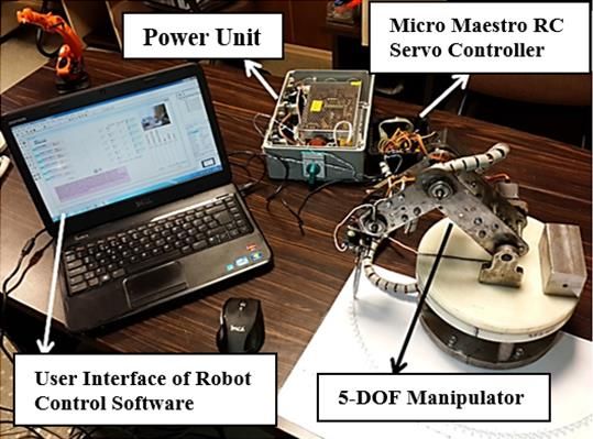
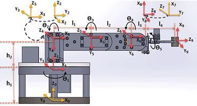
Pamukkale Univ Muh Bilim Derg, 26(2), 392-401, 2020
 S. Uzuner, N. Akkus, M. Toz

inverse kinematic problem of a five DOF serial robot intersecting on the same point while the axes of an offset wrist
manipulator through a method called virtual joint approach. are not intersecting on the same point. Therefore, the proposed
Sarıyıldız and his colleagues [10] compared three different methods generally apply to a single mechanism or to a group of
screw theory-based methods in order to solve the inverse mechanisms. In the present study, a five DOF serial robot
kinematic problem of serial industrial robot manipulators. Park manipulator was designed and implemented using five revolute
et al. [11] also proposed an iterative algorithm for the inverse joints. The analytical method was not preferred because the
kinematic solution of a five DOF serial robotic mechanism with solution of the inverse kinematic problem of this mechanism is
offset wrist. Like the study of Kucuk and Bingül [8], this not analytically applicable. In addition, optimization or artificial
algorithm also starts with an estimated orientation value and neural network-based methods were not adopted because of
iteratively reaches the solution. Sheng et al. [12] proposed a their long processing time and random values used in the initial
geometric inverse kinematic solution method for planar serial stage. Instead, a method similar to the one proposed in [8] and
robot mechanisms that have redundant DOFs and tested their [11] was employed in order to solve the inverse kinematic
method on a sample of five DOF mechanism. El-Sherbiny et al. problem of the mechanism. In this proposed method, first, the
[13] tested the performance of artificial neural networks, fuzzy angle of first joint is obtained analytically, then the angle of
logic, and Genetic Algorithm-based methods which are used for second joint is selected by a simple search technique and then
inverse kinematic solution of serial robot mechanisms tested other joint variables are obtained analytically. It should be
on a five DOF mechanism and then compared the results. noted that the proposed mechanism and the method were given
Chaichawananit and Saiyod [14] proposed the A * algorithm for in the MSc Thesis by Uzuner[27]. The difference between this
solving the inverse kinematic problem of serial robots. Feng et method and other methods in the literature is that no estimated
al. [15], used feed forward neural networks with a novel value is used at the beginning stage and only one angle value is
learning algorithm called extreme learning machine (ELM) for searched in the algorithm and the others are analytically
solving the inverse kinematics problem of serial robot calculated. In this way, process time is reduced. The proposed
manipulators. In another study, Kucuk and Bingül [16] mechanism was realized using RC servo motors to perform
proposed a new numerical algorithm, called NIKA for solving rotational movements. The proposed mechanism is designed to
inverse kinematic problem of the serial robot manipulators be controlled by an open loop control system. Thus, a POLOLU
with offset wrist. Aristidou and Lasenby [17] proposed a new Micro Maestro Servo controller was used to send the control
heuristic iterative method called Forward and Backward signals from the user interface program to the motors. Apart
Reaching Inverse Kinematics (FABRIK), for solving the inverse from these, other equipment (power supply, etc.) are chosen in
kinematic problem of the serial robot mechanisms. This relation to the needs of the mechanism. In addition, a graphical
approach uses a forward and backward iterative approach to user interface has been designed through the Visual Basic
find the solutions. Toz [18], proposed to use Ant Colony programming language to help the user control the robot
Optimization Algorithm for solving the inverse kinematic mechanism. In order to test the effectiveness of the proposed
problem of a six DOF serial robot manipulator with offset wrist. method, two different trajectories, linear and arc-shaped
Dereli and Köker [19] solved the inverse kinematics problem of trajectories, were used and both the theoretical results and the
a seven DOF redundant serial robot manipulator by using experimental results were obtained by the experiments on the
different forms of the PSO algorithm and concluded that PSO developed mechanism. The contributions of this work are as
forms that use inertia weight parameters are more powerful following:
than the standard one. In another study Dereli and Köker [20], 1. A five (DOF) serial robot manipulator was designed
solved the inverse kinematics problem of the same mechanism and implemented,
by a quantum behaved PSO algorithm. In [21], Li et al. designed
a bio-inspired humanoid torso for the humanoid robots and 2. The inverse kinematics problem of the designed
solved the inverse kinematics problem of the mechanism by an mechanism was solved by using a novel method that
algorithm that obtained as combining the chaos optimization consist of an analytical method and a simple search
and the quasi-Newton method. The authors found that the method,
proposed hybrid method is more effective than the Newton- 3. The advantages of the proposed method are, there is
type methods in solving the inverse kinematics problem. no estimate value of any joints is required before
Hrdina et al. [22] used geometric algebra for solving the inverse inverse kinematics solution and only one angle value
kinematics problem of the planar serial robot manipulators and is searched in the algorithm. Thus, the solutions can
also proposed different approaches for segmentation of the be obtained in 18.6 ms average time that is very
actuating rotations. important in real-time control applications. And the
For the mechanisms of which inverse kinematic problem proposed method with the help of the developed user
cannot be solved analytically, there also exist a number of interface program is successfully used to control the
different methods in the literature besides aforementioned five DOF robotic manipulator in real time. As a final
methods. However, because of the different design strategies of point, the proposed method solves the inverse
the serial robot mechanisms and the different types of the joints kinematics problem while the mechanism is working.
and links used for these robots, there is no specific method that Thus, a nearly continuous moving is provided,
can be generalized to solve the inverse kinematic problem of all 4. A user interface program was written for controlling
the serial robot mechanisms. As an example, the inverse the designed mechanism,
kinematics solution of a six DOF serial robot mechanism that
 5. The proposed inverse kinematic solution method was
have Euler wrist is easier than the inverse kinematics solution
 tested on two different trajectories.
of a robotic arm that uses an offset wrist instead of the Euler
wrist. The reason behind this distinction is the differences The organization of the other sections of this paper is as
between the structures of the Euler and the offset wrists. An follows: In the second section, the design steps of the serial
Euler wrist is composed of three joints that have their axes are robot mechanism were briefly described. In the third section,

 393
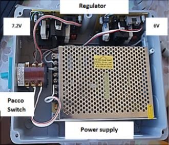
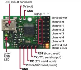
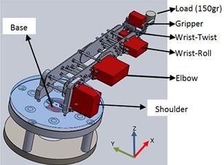
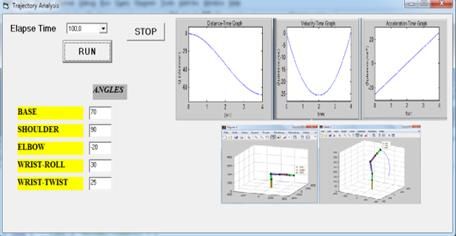
Pamukkale Univ Muh Bilim Derg, 26(2), 392-401, 2020
 S. Uzuner, N. Akkus, M. Toz

the forward and inverse kinematic equations of the designed The most important step with respect to the mechanical design
mechanism were obtained using the DH method and the of serial robot mechanisms is the choice of motor for each joint
inverse kinematic problem of the proposed mechanism was [23]. In the present study, RC servo motors were used for the
solved. In the fourth section, experimental studies and their joints of the mechanism. The properties of the motors were
results were presented, and in the last section, the findings given in Table 2.
were summarized. Table 2. Parameters of the selected RC servomotors.
 2 5 DOF serial robot mechanism and the Axis Torque (Nm)
 design steps Motor of Gripper 0.42168 Nm
 Motor of Wrist-Roll 0.4903325 Nm
The proposed serial robot mechanism consists of five revolute Motor of Wrist-Twist 1.2552512 Nm
joints and a gripper as end-effector (Figure 1). The design steps Motor of Base 2.941995 Nm
of the mechanism are as follows; Motor of Elbow 3.9 Nm
 Motor of Shoulder 2.941995 Nm
 2.2 Design of electronics
 The electronic part of the designed serial robot mechanism
 involves the power supply and the control unit. There are six
 servo motors in the system. Three of them require 7.2 V input
 voltage and the other three require 6 V input voltage. For this
 reason, two different regulator circuits were designed for the 6
 V motor and 7.2 V motor. Micro Maestro 6 Channel USB Servo
 Controller was used as the control unit of the developed system.
 This unit allows controlling the speed and acceleration of each
 motor separately. Figure 3 displays the power supply and
 control unit.

 Figure 1. The designed robotic system [27].
2.1 Mechanical design
Since the mechanism was designed for testing purposes, the
dimensions of the mechanism were determined accordingly
within the limits that the mechanism can be used on an
experiment table. It was also determined that the end effector
has a capacity to carry up to 150 g. The CAD drawing of the
developed mechanism was shown in Figure 2. Regarding the (a) (b)
mechanical structure, there are some mechanical limitations in Figure 3. Electronic parts of the robotic arm. (a): Power supply
terms of its joints. These limitations are presented in Table 1. and (b): Micro maestro servo controller.
 2.3 User interface program
 The required user interface program to control the developed
 serial robot mechanism was written through the Visual Basic
 programming language. This program is composed of five main
 parts: manual control, trajectory analysis, forward kinematics,
 inverse kinematics, and simulation. Figure 4a) displays the
 main screen of the program. This screen can be used for
 switching other screens according to the user's needs. In the
 manual control section (Figure 4b), each joint of the robot arm
 can be controlled independently of each other. In this section,
 the user was provided with the information of position,
 velocity, and acceleration for end effector and the opportunity
 to control the robot on a trajectory determined in advance and
 Figure 2. CAD drawing of 5-DOF manipülatör [27]. composed of several trajectory points. This part was named
 "serial motion" in the interface program. A series of movements
 Table 1. Mechanical limitations of the mechanism in terms of can be repeated once or they can be performed continuously
 its joints. within a loop as occurring in pick-and-place motions. In the
 Axis Rotation angles trajectory analysis section (Figure 4c), the third order
 Gripper 0~330mm polynomials were used to provide sensitive and vibration-free
 Wrist-Roll 47.32° ~ (-47.64°) motion of the robot. This section provides position, velocity an
 Wrist-Twist 86.75° ~ (-83.34°) acceleration graphics of the end-effector within the desired
 Base 107.26° ~ (-102.8°) time. This program module has also been experimentally tested
 Elbow 95.07° ~ (-84.36°) in a study by Uzuner et al. [24]. In the forward kinematics
 Shoulder 146.831° ~ (-3.19°) section (Figure 4d), the necessary controls for the forward
 kinematics analysis of the mechanism are involved. There are

 394
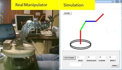
Pamukkale Univ Muh Bilim Derg, 26(2), 392-401, 2020
 S. Uzuner, N. Akkus, M. Toz

two kinds of movements in the forward kinematic analysis obtained solutions are applicable solutions for the robot; so,
section. One of them is the movement according to the there are no solutions within these results which are not
reference (Go with respect to reference) and the other is applicable because of the mechanical limitations of the robot.
according to the last position of the end effector (Go with The reason for the large number of results is that all possible
respect to last position). The motion by the reference makes it solutions in the loop for the second joint variant are obtained
possible to calculate the position of the end effector by the angle with a sensitivity of 0.01 degrees. By choosing any solution in
information inputted to the angle sections at every turn these results (go by the selected one), the motion of the robot
according to the reference coordinate system. On the other can be performed. By selecting the "Go by the least energy"
hand, in the movement according to the last position, the option, the solution with the least sum of the angles among all
angular values of the last position of the end-effector are the solutions will be selected as the solution and the robot arm
accepted as the reference and the movement is performed will go to the specified position by using this solution, this
according to this last position. In addition, "Normal movement" option provides reaching the desired position with minimum
and "Planned movement" options are available. Normal energy. Finally, the Simulation section (Figure 4f) is the part
movement performs robot motion without trajectory planning where the movement of the robot arm is simulated in real time.
between two points while planned movement accomplishes In this section, when the robot arm is performing the desired
robot motion by trajectory planning between any two points. In motion, the simulation of the motion can be seen at the same
the inverse kinematics section (Figure 4e), the inverse time.
kinematics of the mechanism is solved through both analytical
and the simple search techniques. In this section, the desired 3 Forward and inverse kinematics
coordinates of the end effector are entered into the X-Y-Z In this section, the forward and inverse kinematic equations of
sections and the inverse kinematic problem is solved by the the developed serial robot mechanism are obtained by using
proposed method with the help of the solver button. The results the DH method.
obtained are presented in the "result section". All of the

 (a): Main screen. (b): F Manuel control.

 (c): Trajectory analysis. (d): Forward kinematics.

 (e): Inverse kinematics. (f): Simulation.
 Figure 4. Parts of the user interface program.

 395
Pamukkale Univ Muh Bilim Derg, 26(2), 392-401, 2020
 S. Uzuner, N. Akkus, M. Toz

3.1 Forward kinematics According to Table 3, transformation matrices for each of the
The forward kinematic equations of a serial robot mechanism coordinate systems can be written according to Eq. (1) [8].
describe the position and orientation of the end effector of the
 cθi −sθi 0 ai−1
mechanism by the joint parameters according to the base
coordinate system [8]. In this study, DH method was used to i−1 sθi cαi−1 cθi cαi−1 −sαi−1 −sαi−1 di
 iT =[ ] (1)
obtain the forward kinematic equations of the implemented sθi sαi−1 cθi sαi−1 cαi−1 cαi−1 di
mechanism. The placement of the coordinate system on each 0 0 0 1
joint of the mechanism required for this method was shown in
Figure 5. Where, −1 , s and c are transformation matrix between two
 consecutive coordinate systems, sine and cosine, respectively
 (i=1,2,⋯,9). And, the obtained transformation matrices are as
 follows;

 c(θ1 ) −s(θ1 ) 0 0
 0 s(θ ) c(θ1 ) 0 0 1
 1T =[ 1 ]; T=
 0 0 1 h1 2
 0 0 0 1
 0 1 0 0 0 −1 0 e1
 −1 0 0 0 2 1 0 0 0
 [ ]; T = [ ]
 0 0 1 h2 3 0 0 1 0
 0 0 0 1 0 0 0 1

 Figure 5. The replacement of coordinate system for DH
 c(θ2 ) −s(θ2 ) 0 0
 method.
 3 0 0 −1 −e2 4
According to the Figure 5, the DH parameters of the mechanism 4T =[ ]; 5T =
 s(θ2 ) c(θ2 ) 0 0
are obtained as shown in Table 3, [27]. Even though the 0 0 0 1
mechanism has five degrees of freedom, nine coordinate
 c(θ3 ) −s(θ3 ) 0 l1
systems were defined by adding "0", "2", "3" and "7" coordinate
 s(θ ) c(θ3 ) 0 0 5
systems to the joint coordinate systems for accurately [ 3 ]; T = (2)
determination of the mechanical structure of the mechanism. 0 0 1 e3 6
The main reason behind employing the nine coordinate 0 0 0 1
systems instead of five coordinate systems is the e value given c(θ4 ) −s(θ4 ) 0 l2
in Table 3. These values are the offsets between joints and are [s(θ4
 ) c(θ4 ) 0 0
 ]
shown in Figure 6. These offsets make the structure of the 0 0 1 e4
mechanism more stable [27]. 0 0 0 1

 0 −1 0 l3
 6 1 0 0 0
 =[ 7T ];
 0 0 1 e5
 0 0 0 1
 c(θ5 ) −s(θ5 ) 0 0 1 0 0 0
 7 0 0 −1 0 8 0 1 0 0
 8T = [ ]; T = [ ]
 s(θ5 ) c(θ5 ) 0 0 9 0 0 1 l4
 0 0 0 1 0 0 0 1

 The forward kinematic equations of the mechanism can be
 obtained by multiplying these transformation matrices and
 consequently, the transformation matrix which defines the
 Figure 6. The “e” values of the manipulator. position and orientation of the end effector according to the
 base coordinate system can be written as in Eq. (3) [4].
 Table 1. DH parameters [27].
 base
 i α i-1 ai-1 di i end_effectorT = 01T 12T 23T ⋯ n−1nT (3)
 1 0 0 h1=98 mm θ1
 Where _ is the transformation matrix for the end-
 2 0 0 h2=65 mm -90
 3 0 e1=22 mm 0 +90 effector. According to the Eq. (3), the position of the end-
 4 90 0 e2= -7.5 mm θ2 effector in the Cartesian coordinates was obtained as follows;
 5 0 l1=125 mm e3= -5.5 mm θ3 where Px, Py and Pz are the Cartesian coordinates of the end-
 6 0 l2=104 mm e4= -14.5 mm θ4 effector in x, y and z axes, respectively.
 7 0 l3=33.5 mm e5=1.88 mm 90
 8 90 0 0 θ5
 9 0 0 l4=67.5 mm 0

 396
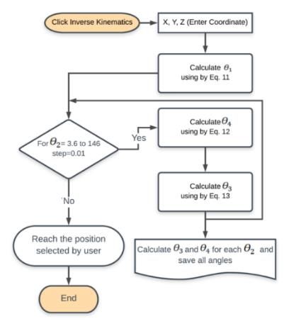
Pamukkale Univ Muh Bilim Derg, 26(2), 392-401, 2020
 S. Uzuner, N. Akkus, M. Toz

 l3 c(θ1 + θ2 + θ3 + θ4 ) l4 c(θ1 + θ2 + θ3 + θ4 ) the inverse of the transformation matrices respectively given in
 = + Eq. (2) [8];
 2 2
 l1 c(θ1 + θ2 ) + l1 c(θ1 − θ2 ) l3 c(θ1 − θ2 − θ3 − θ4 )
 + + [ 01T]−1 09T = [ 01T]−1 01T 12T 23T 34T 45T 56T 67T 78T 89T (8)
 2 2
 l4 c(θ1 − θ2 − θ3 − θ4 ) l2 c(θ1 − θ2 − θ3 )
 + + (4) here, [ 01T]−1 can be written as follows;
 2 2
 l2 c(θ1 + θ2 + θ3 ) c(θ1 ) s(θ1 ) 0 0
 + −s(θ1 ) c(θ1 ) 0 0
 2 [ 01T]−1
 =[ ] (9)
 + s(θ1 )(e1 + e2 + e3 + e4 + e5 ) 0 0 1 −98
 0 0 0 1
 l3 s(θ1 + θ2 + θ3 + θ4 ) l4 s(θ1 + θ2 + θ3 + θ4 ) If we substitute and rearrange Eq. (9) in Eq. (8) and then
 = +
 2 2 compare the corresponding matrix elements on both sides of
 l1 s(θ1 + θ2 ) + l1 s(θ1 − θ2 ) l3 s(θ1 − θ2 − θ3 − θ4 ) the equation reciprocally, the following expression can be
 + +
 2 2 written for the angle θ1 [27].
 l4 s(θ1 − θ2 − θ3 − θ4 ) (5)
 + yc(θ1 ) − xs(θ1 ) = 181/50 (10)
 2
 l2 s(θ1 − θ2 − θ3 ) + l2 s(θ1 + θ2 + θ3 )
 + The θ1 angle can be obtained from this equation as follows;
 2
 − c(θ1 )(e1 + e2 + e3 + e4+ e5 ) θ1 = arctan2 (−x, y)
 (11)
 = h1 + h2 + l2 s(θ2 + θ3 ) + l1 s(θ2 ) + l3 s(θ2 + +arctan2 (∓√x 2 + y 2 − (181⁄50)2 , (181⁄50))
 (6)
 θ3 + θ4 ) + l4 s(θ2 + θ3 + θ4 )
 It should be noted that there are two solutions for the Equation
3.2 Inverse kinematics 11 and the decision about selection of one of these two
 solutions is given by the developed user interface program
The inverse kinematics problem involves the finding of the joint according to the current end-effector position. As a second step,
parameters according to the position and orientation values of the simple search method is used for the angle θ2 to find other
the end effector. The solutions of this problem are closely angle values (Figure 7). The limits of the angle θ2 are given in
related to the design of the manipulator. For this reason, the Table 1 as -3.19° and maximum 146.831°. The minimum
solution methods can differ from one mechanism to another amount of motion of the servomotor used for θ2 is 0.01°. Using
one. If the structure of the manipulator does not allow an these parameters, θ4 and θ3 can be found for each value of the
analytical solution to this problem, this problem can be solved
 θ2 angle as follows [27].
by iterative methods such as Newton-Raphson [25] and
Sequential Monte Carlo [26] methods. The serial robot θ4
manipulator designed in this study has some offsets such as e 2
 (xc(θ1 ) + ys(θ1 ) − 125c(θ2 ))2
values in its joints. In addition, there are four unknown ))2 − 21017
 √1 − +(z − 163 − 125s(θ 2
variables ( 1 , 2 , 3 , 4 ) for the three kinematic equations and ,
 2. 101.104
only Px, Py and Pz are given for the inverse kinematic solution ( )
as seen in Eqs. (4), (5) and (6). For this reason, the inverse = arctan2 ( ) (12)
kinematic problem of this manipulator cannot be completely ) )
 (xc(θ1 + ys(θ1 − 125c(θ2 )) 2

solved analytically. In order to handle this problem, a +(z − 163 − 125s(θ2 ))2 − 21017
combination of analytical method and a basic search technique 2.101.104
is used. In this method, first, the 1 angle is analytically ( ( ) )
calculated. Then, a simple search cycle is initiated in which all θ3=arctan2 ((101 c(θ4) + 104)101 s(θi + θ4) + 104 s(θi )
values of 2 angle are tested with a sensitivity of 0.01 degrees. − 101 s(θ4) 101 c(θi + θ4)
Then, the values of 3 and 4 are analytically calculated in each + 104 c(θi ) , (101 c(θ4) + 104) 101 c(θi + θ4) (13)
iteration of this loop, and in this way, the inverse kinematic + 104 c(θi ) + 101 s(θ4) 101 s(θi + θ4)
 + 104 s(θi ) − (θ2 ) )
problem of the robot is solved. The value of 5 can be any value
that can be determined by the user. This angle just changes the In the equation, θi can be calculated as follows;
orientation of the end effector. With the help of this joint, the ((z -163)c θ4 +(xc(θ1)+ys(θ1)))
robot end effector can pick or place the material to be moved in ((z -163)-125 s(θ2))
the desired orientation. As mentioned above; the analytical
 -101 s (θ4 ) ((xc(θ1)+ ys(θ1 ))-125c(θ2 )) ,
solution for 1 can be obtained as follows; firstly, 09 = θi =arctan2

 ((z - 163)c θ4+(xc(θ1 )+ ys(θ1))) (14)
 _ matrix can be written as in Eq. (7). ((xc(θ1)+ ys(θ1 ))-125c(θ2 ))

 r11 r12 r13 x ( +101 s θ4 ((z -163)-125s(θ2 )) )

 0 r21 r22 r23 y
 9T = [ r r32 r33 z
 ] (7) Finally, since the angle θ5 is only used for the direction of the
 31
 0 0 0 1 end effector and it is independent of the position of the end
 effector, it can take any value. The flowchart of the proposed
Where , = 0,1,2 represents the rotational elements of the method was given in Figure 7, [27].
transformation matrix, while x, y and z are the elements of the
position vector of the end effector. The inverse kinematic 3.3 Applications of inverse kinematics
equations of the manipulator can be obtained by multiplying In this section, the designed serial robot mechanism was tested
 by using two different trajectories. The first one is an arc-

 397

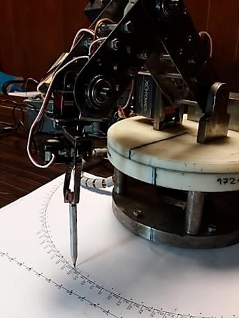
Pamukkale Univ Muh Bilim Derg, 26(2), 392-401, 2020
 S. Uzuner, N. Akkus, M. Toz

shaped with 58 points, and the other is a linear trajectory that The points of each trajectory were defined as the position of the
is divided into 29 points. These trajectories were shown in end effector of the manipulator and the inverse kinematic
Figure 8. In order to see the trajectories drawn by the robot, the problem was solved through the method presented in the
center of the robot base was located to the origin (0, 0) of a previous section. The joint angle parameters obtained by this
Cartesian coordinate system on a paper that was used for the method were applied to the serial robot mechanism and the
trajectory drawn performed by the robot (Figure 9). obtained results were drawn by a pencil used as the end
 effector of the mechanism. It should be noted that the inverse
 kinematics solution of the trajectory points is obtained while
 the mechanism is following that trajectory. As the mechanism
 is moving between two points, the inverse kinematics solution
 for the next point is being calculated. Therefore, a nearly
 continuous moving is provided. The test setup used was shown
 in Figure 9. The inverse kinematic results obtained by the
 proposed method are presented in Table 4 for the arc-shaped
 trajectory and in Table 5 for the linear trajectory. In addition, in
 order to evaluate the application results of these solutions, both
 of the trajectories obtained by the proposed method and the
 trajectories drawn by the test system of the robot mechanism
 are drawn on the same graphics together. These were shown in
 Figure 10.
 According to the Figure 10a and Figure 10b it can be seen that
 Figure 7. Flowchart of the proposed method. the proposed method ensures the complete solution of the
 inverse kinematic problem of the mechanism. And according to
 the Figure 10c and Figure 10d, it is seen that the serial robot
 mechanism tracks the arc-shaped trajectory with a maximum
 error of 4.35 mm and linear trajectory with a maximum error
 of 2.55 mm. In light of the obtained results, although the
 position error of the end effector is at millimetre level, it can be
 discussed that these errors are related to the design of the
 mechanism rather than the method of inverse kinematic
 solution. In this context, the design sensitivity is vital especially
 (a): Arc shape trajectory (mm). in serial robots because the errors appearing at every joint
 affect the end effector collectively. The execution time of the
 trajectory of the mechanism is very important regarding the
 control process of a robot mechanism. For this reason, a second
 experiment was carried out to determine the execution time
 values of each trajectory. Ten examples of time values obtained
 for arc-shaped and linear trajectories were given in Tables 6
 and 7, respectively. All experiments were conducted using a
 computer with an Intel® Core ™ i5-2450M 2.50 GHz CPU and 4
 GB of RAM. According to the obtained results, it is seen that an
 (b): Linear trajectory (mm). inverse kinematic problem that cannot be solved analytically
 Figure 8. Desired trajectory points. can be solved by the proposed method approximately in a 1
 second for an arc-shaped trajectory and 0.618 seconds for a
 linear trajectory. It should be noted that these time values are
 the values obtained for solving the inverse kinematic problem
 of the entire trajectory. Based on these results, the average
 inverse kinematic solution time for a trajectory point is 18.6 ms.
 As a last validation of the proposed method, two error analysis
 methods, Mean Squared Error (MSE) and Root Mean Square
 Error (RMSE) were used. The error analyses were performed
 for both of the results of the proposed method and the results
 obtained by the mechanism. The MSE and RMSE were
 calculated for the X and Y coordinates of the trajectory points
 separately. The obtained results are given in Table 8. According
 to the results, it can be seen that the proposed method followed
 the coordinates of both trajectories in perfect. In contrast to the
 proposed method, the mechanism followed the coordinates of
 both trajectories with some error (Table 8). In light of these
 results, it can be said that the errors emerged during the robot's
 tracking the trajectories are because of the mechanism
 Figure 9. Experiments set-up. structure rather than the proposed method.

 398
Pamukkale Univ Muh Bilim Derg, 26(2), 392-401, 2020
 S. Uzuner, N. Akkus, M. Toz

 (a) (c)

 (b) (d)
Figure 10(a): and (b): Trajectory points of the arc shaped and linear trajectories and the inverse kinematic solutions for these points
 obtained by the proposed method, respectively; (c): and (d): Trajectory points of the arc shaped and linear trajectories and the
 inverse kinematic solutions for these points drawn by the mechanism, respectively .
 Table 4. Inverse kinematic solution for the arc shaped trajectory.
 Arc Points
 No Trajectory points (mm) Inverse kinematic solution (Degree)
 X plane Y plane Base (θ1 ) Shoulder (θ2 ) Elbow (θ3 ) Wrist (θ4 )
 1 10.46 -199.73 -88.039 43.57 -84.341 -31.568
 2 21.08 -198.89 -84.987 43.57 -84.341 -31.568
 3 31.63 -197.48 -81.937 43.57 -84.339 -31.576
 4 42.1 -195.52 -78.886 43.57 -84.34 -31.571
 5 52.54 -193 -75.808 43.57 -84.347 -31.545
 6 62.64 -189.94 -72.785 43.57 -84.34 -31.57
 7 72.66 -186.33 -69.734 43.57 -84.338 -31.577
 8 82.84 -182.2 -66.587 43.56 -84.356 -31.447
 9 92.06 -177.56 -63.632 43.57 -84.342 -31.565
 10 101.38 -172.4 -60.579 43.57 -84.339 -31.573
 Table 5. Inverse kinematic solution for the linear trajectory.
 Linear Points
 No Trajectory points (mm) Inverse kinematic solution (Degree)
 X plane Y plane Base (θ1 ) Shoulder (θ2 ) Elbow (θ3 ) Wrist (θ4 )
 1 220 -196 -42.402 14.4 -45.909 -1.305
 2 220 -182 -40.326 18.92 -53.929 -0.64
 3 220 -168 -38.116 22.72 -60.482 -0.533
 4 220 -154 -35.764 26 -66.118 -0.522
 5 220 -140 -33.267 28.86 -70.584 -1.458
 6 220 -126 -30.619 31.38 -75.046 -1.225
 7 220 -112 -27.82 33.59 -79.014 -0.922
 8 220 -98 -24.872 35.51 -82.181 -1.24
 9 220 -84 -21.779 37.14 -84.246 -2.812
 10 220 -70 -18.549 38.37 -84.284 -7.301

 399
Pamukkale Univ Muh Bilim Derg, 26(2), 392-401, 2020
 S. Uzuner, N. Akkus, M. Toz

 Table 6. The results of inverse kinematics and time values for finding these results (arc shaped trajectory) (only 10 samples).
 Arc Points
 No Desired values (mm) Obtained values from the mechanism (mm) Time
 X plane Y plane X plane Y plane (millisecond)
 1 10.46 -199.73 7.45 -198.7 00:00.599
 2 21.08 -198.89 18.39 -198.7 00:00.660
 3 31.63 -197.48 29.38 -197.39 00:00.670
 4 42.1 -195.52 40.09 -196.35 00:00.515
 5 52.54 -193 51.17 -193.34 00:00.508
 6 62.64 -189.94 62.55 -189.75 00:00.524
 7 72.66 -186.33 72.32 -186.41 00:00.568
 8 82.84 -182.2 83.23 -183.02 00:00.568
 9 92.06 -177.56 90.93 -178.32 00:00.518
 10 101.38 -172.4 101.52 -172.78 00:00.577
 Table 7. The result of inverse kinematics and time values for finding these results (linear trajectory) (only 10 samples).
 Linear Points
 No Desired values (mm) Obtained values from the mechanism (mm)
 Time (millisecond)
 X plane Y plane X plane Y plane
 1 220 -196 221.56 -196.87 00:01.010
 2 220 -182 220.59 -180.93 00:01.081
 3 220 -168 220.06 -168.89 00:01.022
 4 220 -154 219.91 -152.17 00:01.199
 5 220 -140 219.27 -137.72 00:01.250
 6 220 -126 218.65 -124.7 00:01.117
 7 220 -112 218.53 -110.43 00:00.860
 8 220 -98 218.5 -96.67 00:00.742
 9 220 -84 218.2 -83.09 00:00.833
 10 220 -70 217.77 -68.9 00:00.783
 Table 8. The error analysis of the purposed method and the mechanism.
 The method of error MSE (X axis coordinates of the MSE (Y axis coordinates of the
 Trajectory
 analysis robot) robot)
 MSE 0 0
 Linear shaped (theoretical*)
 RMSE 0.001 0.001
 MSE 0 0
 Arc shaped (theoretical*)
 RMSE 0.005 0.001
 MSE 1.777 1.920
 Linear shaped (applied**)
 RMSE 1.333 1.386
 Arc shaped (applied**) MSE 2.885 0.355
 RMSE 1.698 0.578
*: Theoretical depict the results calculated for the inverse kinematic solutions obtained by the proposed method.
**: Applied is used to specify the results calculated for the drawn trajectories by the mechanism.

 4 Results and discussion adapted to the serial robots that have the same mechanical
 structures.
In this study, a 5-DOF serial robot mechanism was designed and
implemented. The inverse kinematic problem of the 5 Abbreviations
mechanism was solved by using the analytical method and DOF : Degrees of freedom,
simple search technique together. In addition, a user interface
program was written through the Visual Basic programming
 R : Rotary joint,
language to control the developed mechanism. Finally, the ELM : Extreme learning machine,
proposed inverse kinematic solution method was tested DH : Denavit-hartenberg,
through an arc-shaped trajectory composed of 58 points and a s : Sine,
linear trajectory divided into 29 points. The validation of the
proposed method is performed by using two error analysis
 c : Cosine,
methods, MSE and RMSE. Px, Py, Pz : Cartesian coordinates,

As an overall evaluation, it can be said that the proposed
 ϴ : Joint angle.
method is successfully used to solve the inverse kinematics
 6 References
problem of the designed mechanism in real-time applications.
Moreover, the proposed method can also solve the inverse [1] Yildiz I. “A low-cost and lightweight alternative to
kinematics problem of the mechanism while it is working. rehabilitation robots: omnidirectional interactive mobile
Finally, it can be noted that the proposed method can be easily robot for arm rehabilitation”. Arabian Journal for Science
 and Engineering. 43(3), 1053-1059, 2018.

 400
Pamukkale Univ Muh Bilim Derg, 26(2), 392-401, 2020
 S. Uzuner, N. Akkus, M. Toz

[2] Srairi F, Saidi L, Hassam A. “Modelling control and [15] Feng Y, Yao-nan W, Yi-min Y. “Inverse kinematics solution
 optimization of a new swimming microrobot using for robot manipulator based on neural network under
 flatness-fuzzy-based approach for medical applications“. joint subspace”. International Journal of Computers
 Arabian Journal for Science and Engineering, Communications & Control, 7(3), 459-472, 2012.
 43(6), 3249-3258, 2018. [16] Kucuk S, Bingul Z. “Inverse kinematics solutions for
[3] Luo L, Tang Y, Lu Q, Chen X, Zhang P, Zou X. “A vision industrial robot manipulators with offset wrists”. Applied
 methodology for harvesting robot to detect cutting points Mathematical Modelling, 38(7-8), 1983-1999, 2014.
 on peduncles of double overlapping grape clusters in a [17] Aristidou A, Lasenby J. “FABRIK: A fast, iterative solver for
 vineyard”. Computers in Industry, 99, 130-139, 2018. the inverse kinematics problem”. Graphical Models,
[4] Li Y, Zhu H. “A simple optimization method for the design 73(5), 243-260, 2011.
 of a lightweight, explosion-proof housing for a coal mine [18] Toz M. “Inverse kinematic solution of a 6 DOF serial robot
 rescue robot”. Journal of the Brazilian Society of manipulator with offset wrist by using alo algorithm”.
 Mechanical Sciences and Engineering. 40(7), 1-10, 2018. Sigma Journal of Engineering and Natural Sciences,
[5] Craig JJ. “Introduction to robotics: mechanics and control”. Special Issue_ASYU 2016, 8(2), 81-90, 2017.
 Addison-Wesley Publishing Company, 113-144, [19] Dereli S, Köker R. “IW-PSO approach to the inverse
 Boston, USA, 1989. kinematics problem solution of a 7-DOF serial robot
[6] Koker R. “A genetic algorithm approach to a manipulator”. Sigma Journal of Engineering and Natural
 neural-network-based inverse kinematics solution of Sciences, vol. 36(1), 77-85, 2018.
 robotic manipulators based on error minimization”. [20] Dereli S,. Köker R. “A meta-heuristic proposal for inverse
 Information Sciences, 222, 528-543, 2013. kinematics solution of 7-DOF serial robotic manipulator:
[7] Fu Z, Wenyu Y, Zhen Y. “Solution of inverse kinematics for quantum behaved particle swarm algorithm”. Artificial
 6r robot manipulators with offset wrist based on Intelligence Review, 53, 949-964, 2020.
 geometric algebra”. Journal of Mechanisms and Robotics, [21] Li T, Yao P, Luo M, Tan Z, Wang M, Guo Z. “Design and
 5(3), 310081-310087, 2013. kinematics analysis of a novel six-degree-of-freedom
[8] Kucuk S, Bingul Z. “The inverse kinematics solutions of serial humanoid torso”. International Journal of Advanced
 fundamental robot manipulators with offset wrist”. Robotic Systems, 15(1), 1-10, 2018.
 IEEE International Conference on Mechatronics, [22] Hrdina J, Návrat A, Vašík P. “Notes on planar inverse
 Taipei, Taiwan, 10-12 July 2005. kinematics based on geometric algebra”. Advances in
[9] Liu ZZ, Liu HY, Luo Z. “Inverse kinematics analysis of 5 Applied Clifford Algebras, 28(3), 71-84, 2018.
 DOF robot manipulators based on virtual joint method”. [23] Sandoval J, Nouaille L, Poisson G, Parmantier Y. “Kinematic
 Applied Mechanics and Materials, 143, 265-268, 2012. design of a lighting robotic arm for operating room”.
[10] Sariyildiz E, Cakiray E, Temeltas H. “A comparative study Computational Kinematics, Mechanisms and Machine
 of three inverse kinematic methods of serial industrial Science, 50, 44-52, 2018.
 robot manipulators in the screw theory framework”. [24] Uzuner S, Akkuş N, Toz M. “Trajectory planning of a 5-DOF
 International Journal of Advanced Robotic Systems, serial robot manipulator in joint-space”. Journal of
 8(5), 9-24, 2011. Polytechnic, 20(1), 151-157, 2017.
[11] Park J, Kim J M, Park HH, Kim J W, Kang G H, Kim S H. “An [25] Haug EJ. Computer Aided Kinematics and Dynamics of
 iterative algorithm for inverse kinematics of 5-DOF Mechanical Systems. 1st ed. Boston, USA, Allyn and Bacon
 manipulator with offset wrist”. World Academy of Science, Boston 1989.
 Engineering and Technology, 72(6), 12-25, 2012. [26] Courty N, Arnaud E. “Sequential Monte Carlo Inverse
[12] Sheng L, Yiqing W, Qingwei C, Weili H. “A new geometrical kinematics”. Institute National Polytechnique de
 method for the inverse kinematics of the hyper-redundant Grenoble, Avenue Félix Viallet, Grenoble, France Research
 manipulators”. Robotics and Biomimetics, ROBIO'06, Report, 6426, 24, 2008.
 Waikoloa Village, HI, USA, 16-18 September 2006 [27] Uzuner S. A New Approach to The Solution of Inverse
[13] El-Sherbiny A, Elhosseini M A, Haikal AY. “A comparative Kinematics of Industrial Robots with Offset Wrist.
 study of soft computing methods to solve inverse MSc Thesis, Marmara University, İstabul, Turkey, 2012.
 kinematics problem”. Ain Shams Engineering Journal,
 9(4), 2535-2548, 2018.
[14] Chaichawananit J, Saiyod S. “Solving inverse kinematics
 problem of robot arm based on a-star algorithm”.
 13th International Joint Conference on Computer Science
 and Software Engineering (JCSSE), Khon Kaen, Thailand,
 13-15 July 2016.

 401
You can also read