Efficiency of ventilated facades in terms of airflow in the air gap
←
→
Page content transcription
If your browser does not render page correctly, please read the page content below
Studia Geotechnica et Mechanica, 2021; 43(3): 224–236

Original Study                                                                                                    Open Access

Krzysztof Schabowicz*, Łukasz Zawiślak, Paweł Staniów

Efficiency of ventilated facades in terms of airflow
in the air gap
https://doi.org/10.2478/sgem-2021-0014
received April 14, 2021; accepted May 11, 2021.
                                                                       Keywords: ventilated facades; heat transfer; heat
                                                                       transmission; CFD; numerical simulation; energy
Abstract: The gradual exploitation of the natural                      efficient facades.
environment has forced most developed countries to
promote ecological solutions and the development of
sustainable construction. Ventilated facades perfectly                 1 Introduction
match into this trend, and with their appropriate design,
they bring real energy savings. This paper analyzes                    Gradual exploitation of the natural environment has
numerically the influence of the inflowing air, mimicking              forced most developed countries to promote ecological
the wind, on the efficiency of heat removal from the                   solutions, including lower energy consumption and
ventilated space and heat transmission by thermal                      promotion of renewable energy sources. In many European
radiation and conduction through the consecutive layers                countries, the share of renewable energy is already over
of the external wall. For the purpose of comparison, two               50%, with the Scandinavian countries being the pioneers
variants of ventilated facade were adopted: open and                   in this statistic. The European Green Deal includes a goal
closed joints, at different wind speeds prevailing outside.            for Europe to be a completely climate-neutral continent,
The results obtained show that in windless weather, the                a target to be reached in 2050. Figure 1 shows the share
ventilated facade with open joints shows higher heat                   of renewable energy sources in each European country
removal efficiency and thus lower heat transmission to                 based on 2018 data.
the building interior. At higher wind speeds of 5 m/s, the                  Citing 2018 data from Eurostat, the energy split
open-joint and closed-joint ventilated facades achieve                 attributable to the buildings sector is 25.8% and services
similar heat transfer efficiency, and the prevailing                   14.2%, which together amounts to 40% [1] of total energy
temperature inside the building for the two technologies               consumption (Figure 2). Compared to 2016, this gives an
is almost identical. Subsequent increments of incoming                 increase of 0.8 percentage points.
wind on the building result in minimal differences in the                   The concept of environmentalism in construction has
heat transmission to the building interior, representing               a place in sustainable construction, which aims to create
changes of about 0.1°C at increments of another 5 m/s of               buildings, with an eye to the future, that are non-polluting
incoming wind. Conscious use of this facade technology,                and user-friendly. In sustainable construction, there are
along with appropriate urban design of cities, can help                several multi-criteria building rating systems, and these
reduce the energy needed to cool buildings during the                  include BREEAM and LEED. Certification with these
summer period.                                                         systems means having the lowest possible negative impact
                                                                       on the environment during the life cycle of a building.
                                                                       Both of these systems analyze similar components such as
*Corresponding author: Krzysztof Schabowicz, Wrocław University        energy, water, building materials, and waste. The concept
of Science and Technology, Faculty of Civil Engineering, Department
                                                                       of reducing energy consumption is fundamental to
of Construction Technology, Wybrzeże Wyspiańskiego 27, 50-370
Wrocław, Poland, E-mail: krzysztof.schabowicz@pwr.edu.pl, ORCID:       sustainable construction. Buildings made in sustainable
0000-0001-6320-9539                                                    construction systems are characterized by high comfort of
Łukasz Zawiślak, Wrocław University of Science and Technology,         use of these buildings. The assessment of comfort of use
Faculty of Civil Engineering, Department of Construction Technology,   shall be carried out through various indicator assessments
Wybrzeże Wyspiańskiego 27, 50-370 Wrocław, Poland, ORCID: 0000-
                                                                       [2].
0003-2828-5899
Paweł Staniów, Wrocław University of Science and Technology,
                                                                            One of the basic elements of energy efficient buildings
Faculty of Civil Engineering, Wybrzeże Wyspiańskiego 27, 50-370        is a properly constructed facade, which is the largest
Wrocław, Poland, ORCID: 0000-0001-6266-293X                            area of contact with the environment. The facade has to

  Open Access. © 2021 rzysztof Schabowicz, Łukasz Zawiślak, Paweł Staniów, published by Sciendo.           This work is licensed under
the Creative Commons Attribution alone 4.0 License.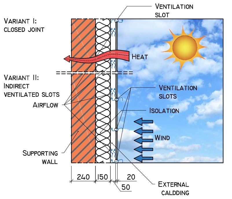
Efficiency of ventilated facades in terms of airflow in the air gap   225

Figure 1: Share of energy from renewable sources, 2018 [1].

                                                                           We distinguish between several technical facade
                                                                       solutions:
                                                                       – ETICS (External Thermal Insulation Composite
                                                                           System) facade, commonly known as light-wet method
                                                                       – Traditional plasters
                                                                       – Ventilated facade

                                                                       A ventilated facade is an ideal solution for sustainable
                                                                       building. A ventilated facade is the technical solution
                                                                       for the top layer of an exterior wall consisting of an
                                                                       external facade cladding that is mechanically or
                                                                       adhesively attached to a substructure. The substructure is
                                                                       mechanically fastened to the exterior wall of the building
                                                                       through consoles. There are many suppliers of these
                                                                       systems on the market, ensuring that the requirements of
                                                                       the most demanding purchasers (e.g., in terms of Passive
                                                                       Houses) are met. Unfortunately, various regulations
                                                                       should be taken into account which may repeatedly
                                                                       prevent the use of these elements on facades (e.g.,
Figure 2: Percentage distribution of energy consumption by sector
in 2018 [1].                                                           zoning plans in particular places or other regulations).
                                                                       External facade claddings used in ventilated facades can
                                                                       be made of various materials, e.g., fibre-cement boards,
protect the building from high and low temperatures,                   concrete boards, steel elements, ceramic elements, and
sunlight, wind, and precipitation. We define the facade                other composite elements. External facade claddings
as the surface layers of the external wall, including all its          are usually installed in accordance with the individual
elements that extend beyond the external wall structure.               technical design of the facade and the requirements
In the case of a veneer, we speak only of its visual element,          set out by the product manufacturer. They are non-
visible on the building.                                               load-bearing elements, bearing only their own weight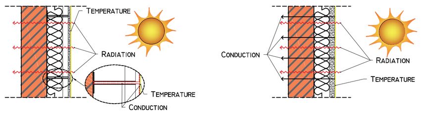
226 Krzysztof Schabowicz, Łukasz Zawiślak, Paweł Staniów
a) b)
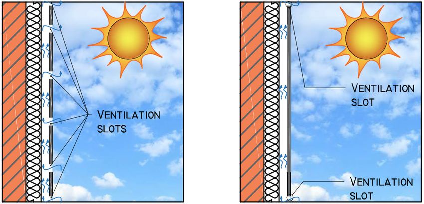
Figure 3: Types of ventilated facades: a) with open joints; b) with closed joints [6].
and the environmental influences of snow, wind, and of these ventilated facade technologies are shown in
temperature. External facade claddings do not ensure the Figure 3 [6].
airtightness of the building, but only to a certain extent A ventilated facade ensures that the effect of heat
provide protection of the external surface of the wall to transfer from the environment, especially on summer
which the facade or insulation is attached. A ventilated and sunny days, to the building interior is reduced. This
facade is a complete set of individual components that is caused by limited thermal conduction. The higher
make up a system solution. The standard specifying the efficiency of a ventilated facade, compared to an ETICS
requirements for the complete ventilated facade system facade, in terms of limiting heat transfer through thermal
is ETAG 034-1 [3], where the individual components of conduction is shown in Figure 4. Thermal conduction, i.e.,
the entire ventilated facade system must additionally heat transfer through solids in the case of an ETICS facade,
meet national requirements. The special feature of a takes place through the entire surface, while in the case of
ventilated facade is the air gap (also called ventilated a ventilated facade, it takes place only through consoles,
space) between the external facade cladding and the which mediate between the external facade cladding and
insulation layer, or the supporting wall if no insulation the external wall.
layer is used. The ventilation space is according to ETAG
034-1 [3] at least 20 mm, but locally it may be reduced to
5–10 mm, depending on the cladding and substructure, 2 Literature Overview
provided that it is verified that this does not affect
the efficiency function of the entire complete system. Naboni in [7] shows that a ventilated facade is a very
Literature sources specify ventilation space dimensions good solution in summer, reducing the heat build-up in
in the range of 20–50 mm [4], [5]. Some sources also the building. This is due to the reduction of conduction
quote higher values, e.g., from 40 to 100 mm [6]. A more by solids. Naboni took a building in Milan as a baseline.
important parameter, independent of the dimension of During the study, the south wall of the building was taken
the ventilation space, is to adequately enable the flow of as representative, in both summer and winter. In both
air through the ventilation space. This is ensured not only seasons, the use of a ventilated facade resulted in benefits
by the dimension of the ventilation space but also by the such as a lower exterior wall temperature on the inside in
appropriate number of ventilation slots – allowing air to the summer and a higher exterior wall temperature on the
enter the space. inside in the winter.
Because of the way air can enter and exchange in the The question should be asked, is a ventilated facade
ventilation space, we distinguish two types of ventilated a good heat transfer limitation under all conditions? What
facades: with closed joints, referred to as opaque ventilated happens in the case of windless conditions? Authors of the
facade, and open-joint ventilated facade. Examples article [8] analyzed the airflow in the ventilation space of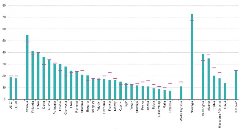
Efficiency of ventilated facades in terms of airflow in the air gap   227

                                    a)                                                                      b)
Figure 4: Heat transfer in a) ventilated facade; b) ETICS facade.

a ventilated facade. In the study, three different situations               used the simulation tools TRNSYS and TRNFlow for the
of inflow velocity of air simulating wind were analyzed.                    study, and weather data recorded during the test period
The results of the simulations conducted revealed that in                   for the coldest and warmest seasons were used as input
the absence of incoming air, the airflow in the ventilation                 to the program. The experimental monitoring included
space is generated only by the buoyancy effect, which                       measurements of an existing building in Valencia for
is directly influenced by solar radiation. In addition, a                   a period of one year. By using temperature sensors in
correlation was noted between the external wind speed                       the experimental model, it was possible to read the
and the air speed inside the ventilation space. The authors                 temperature differences occurring in the envelope. The
in the paper [9] indicate for the sunny part of the building,               temperature from the numerical model was compared
energy savings in the range of 47–51% compared to an                        with the temperature results of the experimental model,
ETICS facade. Authors of [5] focus on the analysis of airflow               at intervals of about 10 minutes. The comparison of the
in the facade with open and closed joints. The research                     numerical model and the experimental model showed
methodology consisted in creating a 2D numerical model                      deviations in temperature results of about 15–20%. Based
considering material and meteorological data and then                       on the study, the authors showed that by recovering heat
analyzing the air vectors in the ventilation space. To verify               from the ventilation space of the facade, it is possible to
the model, thermographic measurements were performed                        reduce the energy demand in the experimental building
using an infrared camera in a reference building in                         by almost 75%, considering the analysis of the south, east,
Madrid. The numerical tests performed and the tests                         and west facades. It was also shown that it is possible to
in the reference building showed that in the open-joint                     save electricity for the use of air conditioning by almost
technology, the internal temperatures increase with the                     10%, taking into account the analysis of ventilated facades
height of the building, and the increase in temperatures                    compared to airtight facades.
is greater than that in the closed-joint technology. On the                      It should be noted that research is also ongoing
other hand, with respect to temperatures in the whole                       on more complex system for integrating facade (also
envelope, closed joints give a higher temperature in the                    ventilated facade), called Trombe Wall [10], systems
envelope – ventilation space, but it is better dissipated,                  with supporting wall. Trombe Wall makes it even more
resulting in lower heat transferred to the building. The                    possible to reduce the energy needed for the maintenance
simulation results also show that the greater the solar                     of buildings than only ventilation facade systems.
radiation, the more electricity needed to cool the building
with air conditioning can be saved with this type of facade.
After analyzing the airflow, it can be clearly stated that the              3 Building a Numerical Model and
airflow velocity inside the ventilation space in the case of
open joints is about five times higher than that in the case
                                                                            Adopting Assumptions for the
of closed joints, and it is highly correlated with the height               Simulation
of the location of the intermediate ventilation slots, used
to supply air to the interior of the ventilation space.                     In order to solve the scientific question concerning
     In scientific papers, we can also find considerations                  the verification of the airflow in the ventilation space
on heat recovery from ventilation spaces [9]. The authors                   on the influence of the performance of the ventilated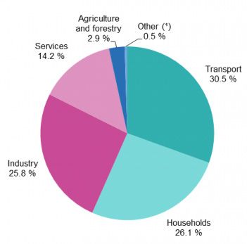
228       Krzysztof Schabowicz, Łukasz Zawiślak, Paweł Staniów

facade, numerical analyses were performed using CFD              ventilation slots, reproducing the facade panel assembly
(Computational Fluid Dynamic) software and Ansys                 and located every approximately 1 m, each 20 mm wide.
Fluent module based on Navier-Stokes equations. The              The adopted model schemes are shown in Figure 5.
choice of software was based on the experience presented               For the purpose of the case, the part of the facade
in [8], [11], [12], [13], in which similar problems were         without openings for windows and doors, at a height of
solved using this software. Authors in the paper [13]            one story, was taken into account. In the case of buildings,
while performing numerical analyses also performed               it is necessary to remember a number of thermal bridging
their validation with experimental studies and the results       due to window joinery and door frames, or structure
confirmed the relevance of using this type of analysis. In       attachment mount. These elements have a negative
this paper, we adopted k-ε (RNG) as the numerical flow           impact on the transmission of heat inside the building.
model, as discussed by Launder in [14]. On the other hand,
Chen [15] showed that the accuracy of the flow model
adopted in this way is good and applicable to this type          3.2 Assumptions for the numerical model
of tasks. Thermal radiation model based on the study by
Chui [16] was adopted as DO (discrete ordinates), which          For the purposes of the numerical analysis, five variants
was presented as fast and accurate.                              of air inflow were assumed to simulate wind at the facade,
                                                                 with the following wind speeds: 0, 2.5, 5, 10, and 15 m/s.
                                                                 Additionally, the influence of temperature was taken into
3.1 Technological and material assumptions                       account, and this was done based on the standard: PN-EN
of the numerical model                                           1991-1-5:2005: Eurocode 1: Actions on structures – Part 1-5:
                                                                 General actions – Thermal actions [4]. The computational
The problem of the efficiency of ventilated facades and          situation was based on the effects of temperature and
the method of extracting air from the ventilation space          insolation during the summer. The facade was located
are not well recognized in the scientific literature. The        in Poland and was situated on the south side due to the
only general requirements for the minimum width of               greatest insolation. It was assumed that this facade will
a ventilation space are indicated: for ETAG 034-1 [3], it        be made in the so-called dark colors due to the greatest
is 20 mm, but a constriction of 5–10 mm is permissible.          absorption of sunlight. Parameters related to such
Unfortunately, there is no information on the efficiency         assumptions are as follows:
of removal of hot air from the ventilation space under           – Outdoor temperature 38°C (311.15 K)
different external wind conditions. It is assumed that there     – Indoor temperature 20°C (293.15 K)
is always air movement in the ventilation space, at least to     – Additional temperature difference due to insolation
a minimum extent, since there is always air movement in               42°C
the atmosphere. ETAG 034-1 [3] imposes on designers also         – Total temperature acting on the facade at peak 38°C +
an obligation to ensure adequate airflow in the ventilation           42°C = 80°C (353.15 K)
space.
     For the purposes of the article, numerical models were
adopted using two types of ventilated facades: with closed       3.3 Numerical model
joints and with open joints. These models were developed
with identical materials, namely: the supporting wall was        Ansys Fluent in the Ansys Workbench module was
made of 240-mm-thick silicate blocks, thermal insulation         used for the numerical study. The model was built as
was made of 150-mm-thick polyurethane, and the external          two-dimensional (2D). In order to represent the global
cladding was made of fibre-cement boards in the so-called        conditions of airflow and exchange and heat transfer,
dark color and 20 mm thick. The total height of the model        the following model dimensions were assumed: width
was assumed to be 4 m. The models included a ventilation         2390 mm and height 4000 mm. In the middle plane of the
space of 50 mm between the insulation and the external           model, a wall was modeled so that there is air space on
cladding made of fibre-cement board. For the model with          both sides of the wall. According to the authors, the model
closed joints, air entered the ventilation space through         so adopted makes it possible to reproduce the global
two ventilation slots at the bottom and top of the outer         conditions of airflow (outdoors) and heat transfer. The
cladding, each 30 mm wide. In the case of the model with         wind is simulated by an inflow of air with a temperature
open joints, air enters not only through the previously          equal to 311.15 K, and an appropriate wind speed,
mentioned ventilation slots but also through intermediate        depending on the case under consideration. In addition, a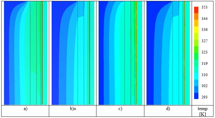
Efficiency of ventilated facades in terms of airflow in the air gap   229

Figure 5: Facade diagrams for numerical simulations of ventilated facade.

corresponding temperature of 353.15 K was set at the outer             of a ventilated facade with closed joints (Figure 7(a) and
edge of the fibre-cement board to simulate insolation. It              (b)), aberrations are noticeable at the lower ventilation
was assumed that the conditions inside the building are                slot – the flow there assumes a disturbed shape, while the
constant, and the air inside has an initial temperature of             airflow inside the ventilation space is constant: laminar.
293.15 K and is not exchanged or cooled. Triangular three-             In the case of facades with open joints, it is noticeable
node elements were used to create the finite element                   that intermediate ventilation slots also participate in the
mesh. The dimensions of the individual finite elements                 supply of air inside the ventilation space. Additionally, it
were selected according to the location with sizes ranging             is possible to separate the ventilation slots which supply
from 1 to 50 mm. Numerical simulation results.                         air (lower and lower – intermediate) and those which
                                                                       receive air (upper and upper – intermediate).
                                                                            Airflow also influences the temperatures inside the
4 Results of Numerical Simulations                                     ventilation space, which translates into room temperatures
                                                                       as well. Maps of the course of temperatures are presented
In order to verify the scientific issue, measurement                   in Figure 8, for variants of models identical as assumed
points were located in two technological variants of the               in Figure 7. On the example of Figure 8 a) and c), it may
ventilated facade: closed and open joints. Locations of                be noticed that a larger number of ventilation slots allows
points, in which temperature measurements were made,                   for supplying larger amounts of air inside the ventilation
are shown in Figure 6.                                                 space. The temperatures inside the ventilation space are
     Figure 7 presents the airflow for ventilated facade               more favorable for the ventilated facade with closed joints;
variants with closed (Figure 7(a) and (b)) and open                    the temperature inside is 313.8 (for a wind speed of 2.5
joints (Figure 7(c) and (d)), for two different speeds of air          m/s), vs. 315.6 K on average for open joints. The trend of
inflow simulating the wind: 2.5 and 10 m/s. In the case                lower temperature inside the ventilation space applies to
230 Krzysztof Schabowicz, Łukasz Zawiślak, Paweł Staniów
all cases of wind speed. This is due to the smaller amount
of air supplied through the ventilation slots and the greater
transfer of cold through the wall from inside the space.
A tabular summary of temperatures and flow velocities
for variants of a ventilated facade in the technology of
closed and open joints, depending on the speed of the
incoming air, is presented in Table 1. For a ventilated
facade with open joints, more measuring points have been
adopted in order to obtain as large an overview as possible
of the phenomena occurring inside the ventilation space
and on the external side of the facade cladding.
As the results below show, as the height in the facade
increases, the temperature inside decreases, and this may
indicate that ventilated facades are an excellent solution
in buildings of high height.
For the ventilated facade with closed joints as shown
in Figure 6, air velocity and temperature were measured
at two points. As shown in Figure 9, the temperature in
a) b) the ventilated space at point 10, even with the minimum
design air velocity of 2.5 m/s coming in at the facade,
Figure 6: Location of temperature measurement points: a) closed-
shows very good heat dissipation. The temperature at this
joint ventilated facade; b) open-joint ventilated facade. point is 2.3 K higher than the temperature at the air coming
into the facade at 5 m/s. For higher incoming air velocities,
the temperature differences inside the ventilation space
70
53
35
18
0
a) b) c) d) speed
[m/s]
Figure 7: Airflow for individual numerical models: a) closed joint: 2.5 m/s; b) closed joint: 10 m/s; c) open joint: 2.5 m/s; d) open joint: 10 m/s.Efficiency of ventilated facades in terms of airflow in the air gap 231
Figure 8: Temperature course for individual numerical models: a) closed joint: 2.5 m/s; b) closed joint: 10 m/s; c) open joint: 2.5 m/s; d)
open joint: 10 m/s.
Table 1. Summary of temperatures and air velocities for measurement points.
Wind Point 10 Point 11 Point 16 Point 17 Point 18 Point 19 Point 20 Point 21
speed Temp Speed Temp Speed Temp Speed Temp Speed Temp Speed Temp Speed Temp Speed Temp Speed
K m/s K m/s K m/s K m/s K m/s K m/s K m/s K m/s
Close 0.0 351.8 0.0 352.7 0.0
joint
2.5 313.8 4.6 315.1 6.0
5.0 311.5 7.8 311.7 13.9
10.0 311.4 14.8 311.4 27.8
15.0 311.3 32.0 311.3 41.7
Open 0.0 351.9 0.0 351.8 0.0 351.7 0.0 351.7 0.0 352.7 0.0 352.7 0.0
joint
2.5 313.4 3.8 316.0 5.2 317.2 5.6 317.2 4.0 314.6 4.5 314.4 7.4
5.0 312.3 7.8 313.2 11.2 313.0 10.5 312.4 7.4 311.2 11.1 312.0 16.5
10.0 311.8 15.6 312.5 21.7 312.4 20.2 312.0 14.1 311.1 22.3 311.8 33.1
15.0 311.7 23.4 312.2 32.2 312.2 29.9 311.8 20.8 311.2 33.2 311.7 49.7
increase minimally. In the case of air velocity in the difference between the temperature at inflow velocities
ventilation space, the increase is significant in relation to of 2.5 and 5 m/s is 3.4 K. At successively higher inflow
the incoming air velocity, but it does not really increase the velocities, the temperature, as in the previous variant, is
efficiency of better removal of hot air. In the case of Point almost constant. The airflow on the outside of the facade
11, located outside from the facade cladding, the incoming cladding increases linearly with respect to the incoming
air velocity has a greater effect on the temperature air simulating wind. The temperature and flow inside the
removal from the surface of the facade cladding. The ventilation space for Point 11 are shown in Figure 10.232 Krzysztof Schabowicz, Łukasz Zawiślak, Paweł Staniów
Figure 9: Compilation of temperature and air velocity for the ventilated facade with closed joints at Point 10.
Figure 10: Compilation of temperature and air velocity for the ventilated facade with closed joints at Point 11.
For the ventilated facade with open joints, four achieved at 5 m/s elevation wind inflow velocity, and the
measuring points inside the ventilation space and two subsequent increase in the inflow wind velocity does not
measuring points on the outside of the facade cladding increase the efficiency of heat removal from the ventilation
were considered. Similar trends in the behavior of space. This causes that higher velocities do not improve
the temperature change and the difference in airflow the efficiency of heat removal from the ventilation space,
inside the ventilation space and the flows in the open- so the heat transmission to the building interior is not
joint technology as in the variant with closed joints are reduced. At incoming wind speeds to the facade above 5
observed. At the speed of 2.5 m/s of wind inflow to the m/s, no significant changes are observed.
facade, the temperature inside the ventilation space In the case of airflow on the exterior side of the facade
is in the range of 313.4–317.2 K. On the other hand, for cladding for the variant with open joints, the analysis was
the velocity of 5 m/s wind inflow to the elevation, the carried out for two measurement points. For this location,
temperature inside the space is in the range of 311.2–313.0 even the smallest selected air inflow simulating wind –
K. The results are shown graphically in Figure 11. The which was a wind speed of 2.5 m/s into the facade – results
temperature stabilization inside the ventilation space is in nearly identical temperatures. Higher velocities of airEfficiency of ventilated facades in terms of airflow in the air gap 233
Figure 11: Compilation of temperature and airflow velocity for individual measurement points inside the ventilation space for a ventilated
facade with closed joints.
inflow to the facade caused minimal temperature changes for both technological variants of the ventilated facade.
within the facade cladding on the external side, which In addition, it is noticeable that in spite of much better
may suggest that even minimal wind effectively removes air supply and removal in the ventilated facade with open
heat from this location. joints, the temperature course for both variants is similar,
In the previous steps, the analysis of the removal of air which at first seemed impossible. The temperature behind
with a higher temperature from the ventilation space was the facade cladding stabilizes in both variants in the case
carried out, but the question occurred to the authors of the of a 5 m/s wind inflow to the facade, and higher speeds
study: does it influence the temperature inside the room? do not increase the effectiveness of the ventilated facade.
For the purpose of this analysis, a number of consecutive
measuring points were selected on the inner side of the
wall (room side) as well as on the individual wall layers. 5 Conclusions
All measurement points for the course of the temperature
for the facade ventilated in both technologies – open and Ventilated facades fit in very well with the increasing
closed joints – are presented in Figure 13. demands placed on buildings in the field of sustainable
All the results obtained from the tests are summarized construction. The thermal comfort they provide increases
in Table 2. It is noticeable that in the two technological their use not only in regions of the world with high
variants of the ventilated facade, the speed of the temperatures but also in regions with the so-called mild
incoming air on the facade of 2.5 m/s is insufficient for climate.
good removal of hot air; on the other hand, an increase in Numerical studies confirm that the effectiveness
the speed decreases the heat transmission. in terms of heat removal from the ventilation space
The course of the temperature for particular is dependent on the wind speed prevailing outside.
technological variants of the ventilated facade, as well The so-called open-joint technology, despite higher
as for different speeds of the air coming to the facade temperatures in the ventilation space, is more efficient in
simulating the wind, is presented in Figs 14 and 15, terms of lower heat transfer to the inside of the room, not
based on the results contained in Table 2. It can be only in windless weather but also at lower wind speeds
observed that for both closed and open joints, the wind prevailing outside – 2.5 m/s. In the case of wind velocity
speed prevailing outside affects the efficiency of heat coming into the facade of 5 m/s, the performance of
removal from the ventilation space, and in turn affects ventilated facades in the variants of closed and open joints
the lower temperatures inside the room. As an example, reaches similar values. Subsequent increase in the velocity
the temperature difference in Point 7 for the speed of 2.5 of wind inflow to the facade outside minimally affects the
and 5 m/s is about 7 K, and the situation is very similar efficiency of heat removal through the ventilated space,234 Krzysztof Schabowicz, Łukasz Zawiślak, Paweł Staniów Figure 12: Compilation of temperature and air velocity for individual measurement points outside the cladding for a ventilated facade with closed joints. a) b) Figure 13: Location of temperature measurement points: a) closed-joint ventilated facade; b) open-joint ventilated facade. Figure 14: Temperature overview for the control points of the close-joint facade.
Efficiency of ventilated facades in terms of airflow in the air gap           235

Table 2: Compilation of temperatures for measurement points inside the room and within the wall.

          Wind          Point 1      Point 2       Point 3      Point 4       Point 5      Point 6       Point 7       Point 8         Point 9
          speed         Temp         Temp          Temp         Temp          Temp         Temp          Temp          Temp            Temp
                        K            K             K            K             K            K             K             K               K

Close     0.0           293.2        305.1         317.1        329.1         335.3        339.8         340.6         341.7           350.6
joint
          2.5           293.2        298.5         304.0        309.5         312.3        314.4         314.8         315.3           316.5

          5.0           293.2        296.7         300.4        304.0         305.9        307.3         307.6         307.9           311.3

          10.0          293.2        296.7         300.3        304.0         305.9        307.3         307.5         307.9           311.3

          15.0          293.2        296.7         300.3        304.0         305.9        307.3         307.5         307.9           311.3

Open      0.0           293.2        305.1         317.1        329.2         335.3        339.8         340.7         341.7           350.6
joint
          2.5           293.2        298.3         303.5        308.8         311.6        313.5         313.9         314.4           316.1

          5.0           293.2        296.8         300.4        304.1         306.0        307.4         307.6         308.0           311.4

          10.0          293.2        296.7         300.3        304.0         305.9        307.3         307.5         307.9           311.2

          15.0          293.2        296.7         300.3        304.0         305.9        307.2         307.5         307.9           311.2

Figure 15: Temperature overview for the control points of the open-joint facade.

thus reducing heat transmission to the interior. The                      ventilation space, but this influence is much smaller than
analyses carried out in this study have also shown that                   the benefits of their presence.
intermediate ventilation slots, used in a ventilated facade                    It is also very important to consciously use ventilated
with open joints, have a significant effect on air exchange               facades on buildings that will not be shielded from
in the ventilation space. In the example studied, the                     incoming air in order to achieve the greatest possible
intermediate ventilation slots, which are responsible for                 efficiency. Conscious use of this facade technology, along
supplying and removing air from the ventilation space,                    with appropriate urban design of cities, can help reduce
can be clearly distinguished. These slots also introduce                  the energy needed to cool buildings in the summer. The
disturbances and aberrations in the flow inside the                       authors intend to continue this research.
236 Krzysztof Schabowicz, Łukasz Zawiślak, Paweł Staniów
References [19] O. Kopyłow, Elewacje wentylowane - Warunki Techniczne
Wykonania i Odbioru Robót Budowlanych B14/2015.
[20] A. Gagliano, F. Nocera and S. Aneli, “Thermodynamic analysis
[1] Website: https://ec.europa.eu/eurostat/. of ventilated facades under different wind conditions in
[2] A.-J. Romana i N. Maciej, „Wskaźnikowa ocena komfortu summer period,” Energy and Buildings 122, pp. 131-139, 2016.
w budynkach mieszkalnych zlokalizowanych w klimacie [21] C. Aparicio-Fernández, J.-L. Vivancos, P. Ferrer-Gisbert and R.
umiarkowanym,” Izolacje, nr 6, pp. 2-7, 2016. Royo-Pastor, “Energy performance of a ventilated façade by
[3] EOTA ETAG 034 Part 1: Ventilated Cladding Kits comprising simulation with experimental validation,” Applied Thermal
Cladding components and associated fixings. Engineering 66, pp. 563-570, 2014.
[4] EN 1991-1-5: Eurocode 1: Actions onstructures - Part 1-5: [22] ANSYS Fluent Theory Guide.
General actions - Thermal actions. [23] ANSYS Fluent User’s Guide.
[5] C. Sanjuan, M. J. Suárez, M. González, J. Pistono i E. Blanco, [24] EOTA ETAG 034 Part 2: Cladding Kits comprising Cladding
Energy performance of an open-joint ventilated facade components, associated fixings, subframe and possible
compared with a conventional sealed cavity façade, Solar insulation layer.
Energy 85, pp. 1851-1863, 2011. [25] K. Schabowicz, Elewacje wentylowane Technologia Produkcji
[6] M. Ibañez-Puy, M. Vidaurre-Arbizu , J. A. Sacristán-Fernádez i i metody badania płyt włóknisto-cementowych, Wrocław:
C. Martín-Gómez, Opaque Ventilated Façades: Thermal and Oficyna Wydawnicza Politechniki Wrocławskiej, 2018.
energy performance review.,” Renewable and Sustainable [26] EOTA ETAG 034 Part 2: Cladding Kits comprising Cladding
Energy Reviews, Volume 79, pg. 180–191. doi: 10.1016/j. components, associated fixings, subframe and possible
rser.2017.05.059., nr 79, pp. 180-191, 2017. insulation layer.
[7] E. Naboni, „Ventilated opaque walls - A performance simulation [27] M. Suárez, C. Sanjuan, A. Gutiérrez, J. Pistono and E. Blanco,
method and assessment of simulated performance,” w Seminar “Energy evaluation of an horizontal open joint ventilated
Notes at Lawrence Berkeley National Laboratory Environmental façade,” Applied Thermal Engineering 37, pp. 302-313, 2012.
Energy Technologies Division Berkeley, California, USA, May 28
2007.
[8] A. Gagliano, F. Nocera i S. Aneli, „Thermodynamic analysis of
ventilated facades under different wind conditions in summer
period,” Energy and Buildings 122, pp. 131-139, 2016.
[9] C. Aparicio-Fernández, J.-L. Vivancos, P. Ferrer-Gisbert i R.
Royo-Pastor, Energy performance of a ventilated façade by
simulation with experimental validation, Applied Thermal
Engineering 66, pp. 563-570, 2014.
[10] J. Szyszka, J. Kogut, I. Skrzypczak i W. Kokoszka , „Selective
Internal Heat Distribution in Modified Trombe Wall,” IOP
Conference Series: Earth and Environmental Science, tom 4, nr
95, 2017.
[11] M. Chereches, N. C. Chereches i S. Hudisteanu, „Numerical
modeling of solar radiation inside ventilated double-skin
facades,” International journal of heat and technology vol. 33,
No. 4, pp. 246-254, 2015.
[12] M. Chereches, N. C. Chereches i S. Hudisteanu, The influence
of different flow velocities on the heat transfer inside a
ventilated façade, Revista Romana de Inginerie Civila Vol. 5,
No.1, 2014.
[13] L. Cirillo, D. Di Ronza, V. Fardella, O. Manca i S. Nardini,
„Numerical and experimental investigations on a solar chimney
integrated in a building façade., International Journal of Heat
and Technology 33 (4), pp. 246-254, 2015.
[14] B. Launder i D. Spalding, „The numerical computation of
turbulent flows. Computer Methods.,” Computer Methods in
Applied Mechanics and Engineering 3, pp. 269-289, 1974.
[15] Q. Chen, „Comparison of different κ −ε models for indoor
airflow computations.,” Numerical Heat Transfer, Part B, 28,
pp. 353-369, 1995.
[16] E. Chui i G. Raithby, „Computation of radiant heat transfer on
a non-orthogonal mesh using the finite-volume method.,”
Numerical Heat Transfer, Part B, 23, pp. 269-288, 1993.
[17] Website: http://www.breaam.com
[18] Website: http://leed.usgbc.org/leed.htmlYou can also read