EXPERIMENTAL INVESTIGATION ON EFFECTS OF BLUFF-BODY SIZE AND AXIAL AIR INJECTION ON BLOWOFF LIMITS IN SWIRL BURNERS
←
→
Page content transcription
If your browser does not render page correctly, please read the page content below
Journal of Engineering Science and Technology
Vol. 16, No. 3 (2021) 2202 - 2214
© School of Engineering, Taylor’s University

 EXPERIMENTAL INVESTIGATION ON
 EFFECTS OF BLUFF-BODY SIZE AND AXIAL AIR
 INJECTION ON BLOWOFF LIMITS IN SWIRL BURNERS

 FARES A. HATEM*, MOHAMMED AL-FAHHAM, ALI SAFA ALSAEGH,
 ZAID M H AL-DULAIMI, AGUSTIN VALERA-MEDINA

 School of Engineering, Taylor’s University, Taylor's Lakeside Campus,
 No. 1 Jalan Taylor's, 47500, Subang Jaya, Selangor DE, Malaysia
 *Corresponding Author: famer442@gmail.com

 Abstract
 The stability limits of swirl combustors have been considered as a crucial factor
 for obtaining a wide stability operation map. The present global consideration is
 towards using low-carbon emission fuel in gas turbine production sector and,
 many other combustion systems. However, the demands of introducing low-
 carbon emission fuels impose a considerable modification in the combustor
 hardware; consequently, the variation of burner stability operation map. Blowoff
 and flashback are two parameters that determined the margins of stability
 operation in swirl burners, when correlated with equivalence ratio and inlet
 tangential or bulk velocity. This study investigates the effect of hardware
 modification with different bluff-body sizes (external diameter) and flow-field
 manipulation like using axial air injection on blow-off limits in swirl combustors.
 The first part of this study has demonstrated that variation of bluff-body diameter
 alters the blowoff limits significantly. Small central injector (bluff-body)
 diameter displaces blowoff limits towards leaner equivalence ratios with (Φ= 4
 to 4.2); which is favourable for low emission demands. However, the stability
 map became narrower regarding inlet tangential velocities with (w=2.7 to 4.2),
 consequently reducing output power. In contrast, bigger injector diameter leads
 to having blowoff limits occur at a wider range in term of inlet tangential
 velocity(w=2.5-4.5) which means high output power, despite slight displacement
 to the rich region, Φ= 0.5 at high tangential velocity. The second part of this work
 has proposed, a new technique that can replace hardware (bluff-body) by axial
 air-jets which can simulate the physical shape of bluff-body. Using axial air jets
 results in wider operation map, the inlet tangential velocity range is (w=2-8 m/s)
 compare with bluff-body case (w=2.5-4.5 m/s), hence increasing the burner
 output power while keeping its size. The position of air-jet opening inside burner
 plenum alter blowoff limits, baseline Lo=0 and Lo=150 extend the range of inlet
 tangential velocity at which the blowoff occurs, almost (2-8 m/s). While the other
 three positions revealed less range of inlet tangential velocities, as the affected
 by aerodynamic perturbations arise from the clash between axial jets and inlet
 tangential flow.
 Keywords: Blowoff, Axial air-jets, Bluff-body, Premixed swirling flames.

 2202
Experimental Investigation of the Effects of Bluff-Body Size and Axial Air. . . . 2203

1. Introduction
The concerns about keeping or reducing the pollution level in the atmosphere
imposed strict emission regulations on the energy production market. Thus, most
of the OEMs (Original Equipment Manufacturer) has been putting significant
efforts to meet environmentally friendly requirements that set out by either local
governments or international organizations. Almost all combustion systems,
primarily that operated on fossil fuel are needed to fulfil low emission standards.
Gas turbines are receiving special attention among other combustion systems due
to their contribution to the energy market. Introducing alternative fuels that produce
lower harmful pollutants require intensive consideration to employ such fuels
safely in gas turbines with the achievement of optimum performance and output
power. The combustor is an essential part of gas turbines that needs to be
investigated in this context.
 The broad stability operation map is one of the main factors that address the
perfect performance of modern gas turbines combustor. Fulfilment of this target
requires considerable modification of system hardware and careful flow field
manipulation of the premixed mixture are considered as crucial factors. However,
any of the variations mentioned above must take into consideration many
operational factors, such as quality of mixing, flame length, uniformity of fuel
distribution, temperature distribution, flame dynamics and flame attachment [1- 4].
Bluff-bodies, central fuel injectors and solid obstacles are considered as the
traditional technique for flame anchoring and hence downstream static stabilisation
of swirling flames [5-9]. They can also be employed for supplementary firing in
some industrial burners [10-12].
 The fundamental function of central bodies is physically anchoring premixed
flames, it can also affect the downstream combustion process. The contact between
the bluff-body, fresh mixture and combustible mixture can play an important rule
regarding heat exchanging between the flame and the bluff-body itself,
consequently the characteristics of the coherent structure, density ratio, pressure
distribution and blockage ratio [4, 13-15]. Thus bluff-bodies governing blowoff
limits physically represented by flow-field manipulating and chemically through
heat transfer with combustion mixture. Many studies have investigated both effects,
many studies about employment bluff-bodies for flame stabilisation requirements
have been carried out [16-21].
 The geometry and position of the bluff-body govern the shape and position of
the shear layer [22]. Nair and Lieuwen [19] investigated the effect of the bluff-
body on flow field characteristics. They realised that flame near to the cylindrical
bluff-body mounted at the middle of the burner reveals high vorticity magnitudes,
so higher fluid mechanics stretch. This factor links directly to flame extinction,
hence blowoff mechanism. This factor has also previously explained by Yamaguchi
et al. [23]. Chaudhuri and Cetegen [20] studied the characteristics of bluff-body
stabilized conical premixed flames. They have found a gradual narrowing of the
flame cone before blowing off. They also observed that the lean fuel region of the
outer flow cannot sustain the combustion process. Shanbhogue et al. [10] further
proposed blowoff mechanism with using bluff- bodies. They stated that it occurs in
multiple steps; in the beginning, there was local extinction alongside the flame
sheet, then large-scale wake disruption and finally flame blew off.

Journal of Engineering Science and Technology June 2021, Vol. 16(3)
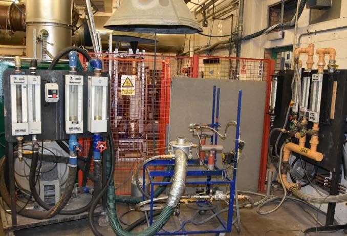
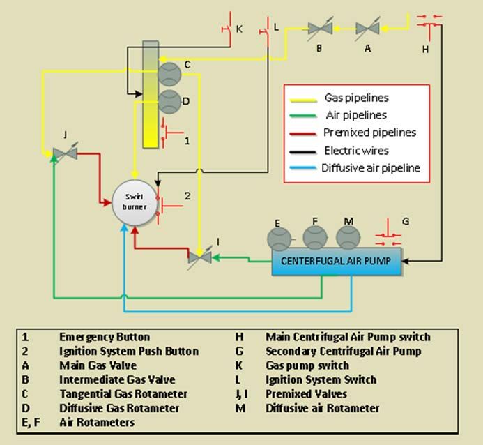
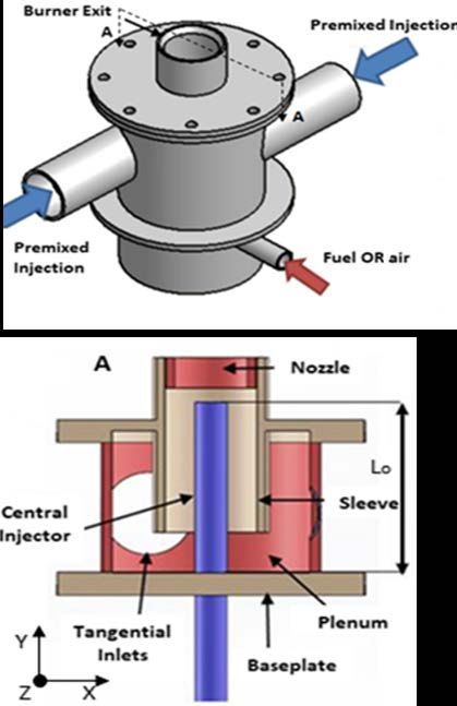
2204 F. A. Hatem et.al

 Although the considerable efforts had done to achieve the best employment of the
bluff-bodies for flame stabilization demands with combustion systems used premixed
swirling flames. However, there are still many issues associated with this technique;
for instance, introducing high hydrogen-containing fuel characterized by high flame
speed and temperature. It shifts the stability operation map of the burner towards the
lean region to avoid potential risks like an explosion. Additionally, most bluff-bodies
are subjected continuously to a harsh environment due to direct contact with flame.
Therefore, the formation of soot and NOx emission, consequently, increase
maintenance cost of life degradation [11, 24, 25]. Moreover, in industrial swirl
burners bluff-bodies also used for injecting diffusive fuel. It can reduce the quality of
mixing accompanied by a significant increase of pollutants. This mode of combustion
is strongly conflicted with ever-growing public demands for lowering greenhouse
emissions. Hence, all these issues impose performing more investigations either by
hardware modification or flow field manipulating.
 Still, there is a lack of entire understanding of the relationship between blowoff
mechanism and bluff-body geometry. This relation governs by physical parameters,
such as the bluff-body size or factors that influence fluid mechanics. Therefore, it
worthy of investigating the effect of such parameters, it is useful to find an
alternative mechanism for flame holding and stabilisation to replace the hardware
(bluff-body) by another technique. This alternate technique can perform the same
function, while keeping a low level of emission with a reduced maintenance cost
of combustors.
 The present work consists of two methods of investigations; the first part of this
study is a continuation exploring of the effect of bluff-body geometry representing
by the outside diameter central fuel injectors on blow-off limits. The second part
explores the difference in a blow-off mechanism and its limits when using axial air
jets for simulating bluff-bodies virtually in swirl burners.

2. Experimental Setup
The testing rig was consisted of tangential swirl burner (150 kW, maximum output
thermal power), gas rotameters, air rotameters, gas valves, air valves and LDA
system. Figure 1(a) shows the testing rig and Fig. 1(b) illustrates the arrangement
of the testing rig during the experiments.
 The tangential swirl burner is illustrated in Figure 2. Some studies have already
used this burner to investigate different flame characteristics [24, 26, 27]. In this
burner, there are two tangential inlets, inlet diameter (ID) is 67 mm for each, opening
inside the plenum, while the exit diameter is 76 mm, to change the inlet diameter of
the inlets, different inserts have been used, while different nozzle configurations have
been used to vary the exit diameter. As different swirl numbers can be achieved from
0.9-3.6 and a low swirl number (0.9) was used in current study.
 The Laser Doppler Anemometry (LDA) Dantec system was used to measure
the instantaneous vorticity magnitude downstream the burner mouth, this system is
one component flow light and working on backscatter mode.

Journal of Engineering Science and Technology June 2021, Vol. 16(3)
Experimental Investigation of the Effects of Bluff-Body Size and Axial Air. . . . 2205

 (a) Testing rig.

 (b) Illustrates the arrangement of the testing rig during the experiments.
 Fig. 1. Experimental setup.

Journal of Engineering Science and Technology June 2021, Vol. 16(3)
2206 F. A. Hatem et.al

 The calibration uncertainty of this system is 0.067%. The measurements
method was implemented based on introducing seeding particles (Aluminum Oxide
AL3O2 of size ~ 10 μm) to the flow downstream burner mouth. LDA detected these
particles (measuring points), and the average 10,000 measuring points was used in
this study.
 In the first part of this study, the burner baseplate was utilised to allow different
diameters of central fuel injector (bluff-body). In this study six bluff-body (central
fuel injector) of different outside diameter 7,12.5,16,19,21, and 23 mm have been
tested. The results presented in this study are based on just three injectors (12.5,21
and 23 mm) as they reveal the most pronounce difference regarding blowoff limits.

 Fig. 2. Tangential swirl burner.

 In the second part of this study, another baseplate was used to allows axial
injection of air jets. The design enabled axial air jets repositioning in the vertical
direction at different Lo positions.
 All experiments were implemented under atmospheric conditions without air
preheating and natural gas (90% methane) was used as fuel. A centrifugal fan was
used for feeding the system via flexible hoses with two banks of rotameters to
control the flow rate. There was one bank for fuel injection control. The readings
errors were ⁓3% for both air and gas flowmeters. The ranging of flow rate for
different operation conditions was from (Reynold number) Re⁓10500 to 30,000.
 The following two modes of fuel injection were used.
 • Premixed mode at the entrance of the tangential inlets of the burner.

Journal of Engineering Science and Technology June 2021, Vol. 16(3)
Experimental Investigation of the Effects of Bluff-Body Size and Axial Air. . . . 2207

 • Diffusive mode via the central injector (this mode just for start-up).
 The overall equivalence ratio (Φ) that considers tangential and central flow
rates were controlled by decreasing/increasing the airflow in the blend while
keeping a constant fuel flow rate.
 The following equations were used to determine the equivalence ratio of all
testing conditions.

 = (1)

where is the stoichiometric fuel to air ratio. This ratio can be determined
according to the equation of the chemical reaction.
CH4 + 2O2 → CO2 + 2H2 O (2)
 Based on the calculation of the molecular weight of the reactants (methane and
oxygen) and by considering that oxygen ratio in the air which is almost (23.2%)
and assume stoichiometric combustion (the condition for complete combustion).
Burning 1 kg of methane requires 17.2 kgs of air. Thus, the stoichiometric fuel to
air ratio is:
 1
 = = 0.058 (3)
 17.2

 Actual fuel to air ratio is calculated by measuring the mass flow rates of fuel
and air according to the following equation:
 ̇
 = (4)
 ̇

where the mass flow rate is calculated by measuring the volume flow rate directly
from rotameters, thus equivalence ratio can be determined for each flow rate. It is
worth mentioning here that in the case of using axial air jets, the amount of air is
determined for the total air mass flow rate, the tangential and axial.
 The inlet tangential velocity is determined according to the continuity equation
depending on the total mass flow rate of the mixture and the entire area of tangential
inlets of the swirl burner.

3. Results and Discussion
3.1. Effect of bluff-body size
Blowoff limits of three central fuel injectors size (diameter) have been determined.
A dimensionless parameter λ which represent the ratio between the bluff-body
diameter and the nozzle inside diameter, has been used for the analysis. Table 1
denotes various λ values.

 Table 1. Various λ values
 Bluff-body λ (Bluff-body diameter/Nozzle
 diameter(mm) inside diameter)
 12.5 0.205
 21 0.345
 23 0.378

Journal of Engineering Science and Technology June 2021, Vol. 16(3)
2208 F. A. Hatem et.al

 As in previous studies, the mean velocities of fuel-air mixtures feed through the
tangential inlets have been used for representing results [24, 26]. Thus, allowing a
fair comparison between cases regardless variation in Re at burner exit arises with
different bluff-body diameter. Moreover, depicting data based on the correlation of
inlet tangential velocity with equivalence ratio (Φ) ease comparison other swirl
burners regardless of their size or power.
 To determine the blowoff limit for each case, stable operation was achieved.
Then inlet tangential fuel was reduced until the flame is eventually blowing off.
This procedure was repeated for flow rates until obtaining all blowoff limits. Then
the measurements were repeated for other bluff-bodies. Figure 3 illustrates the
blow-off limits of the three bluff-bodies. As can be seen, small values of λ (0.205)
results in leaner operation region of the burner (Φ=4 to 4.2), which is favourable to
meet low emission requirements. The inlet tangential velocity range was narrow
(w=2.7 to 4.2 m/s) which reduced output power of the burner.

 Fig. 3. Effect of bluff-body diameter on blow-off limits.

 Increasing λ (0.345) produces a significant raise in the range of burner operation
regarding inlet tangential velocity (w=2.7 to 4.5 m/s). However, there is a noticeable
fluctuation of equivalence ratio values from Φ= 0.42 to 0.49. This variation is not
desirable in terms of stable operation demands of gas turbine combustors.
 Further increase of λ (0.378) results in a steady growth of inlet tangential velocity
values (w=2.5-3.5 m/s) at almost constant equivalence ratio, Φ= 0.45. Then, the inlet
velocity values increase linearly with equivalence ratio values Φ= 0.45-05, before it
is showing a steady increase from w=4 m/s to 4.5 m/s at constant Φ= 0.5. The third
type of bluff-body (λ =0.378) seems reveal the best performance, as it achieves a
wider operation region regarding inlet tangential velocity with less equivalence
fluctuation. Although increasing λ (outside diameter of the bluff-body) moves blow-
off curves to the rich region. It leads to a considerable extending of the stable
operation in terms of inlet tangential velocity. Having a wider operation region is
interesting for high power operation or fuel switching demands as provide in [28].
 The reason behind this difference in blowoff limits is explained here. For a
small size bluff-body, the flame is shifted downstream towards low-velocity region
upon decreasing equivalence ratio to the global limits, to maintain a kinematic

Journal of Engineering Science and Technology June 2021, Vol. 16(3)
Experimental Investigation of the Effects of Bluff-Body Size and Axial Air. . . . 2209

balance between the upstream fresh mixture velocity and flame speed. The
repositioning of the flame leads to overlapping of the flame edge with shear layer
vortices and high strain field and so higher stretch rate along the flame edge which
consolidates the local extinction conditions, hence early blowoff.
 Conversely, the flame can maintain the equilibrium with upcoming flow velocity
in the further upstream position with increasing bluff-body diameter. Hence, flame
edges became less affected by shear layer vortices, as a result, reduce local extinction,
consequently, blowoff limits delay to higher inlet tangential velocities.

3.2. Effect of axial air injection
Introducing axial air injection to simulate bluff-body for stabilizing premixed
swirling flames can control the position of the CRZ and other swirl coherent
structures. Hence it can govern the blowoff limits considerably. However, the ratio
of axial air injection to the total mass flow is crucial in this context; a higher flow
rate could lead to avoiding swirl strength deterioration and lack of mixing. Thus,
based on the previous study [24], the ratio of axial air jet of the total mass flow rate
(3-10%) was used in this study. Figure 4 illustrates the differences in blow-off
limits between bluff-body (central fuel injector) and axial air injection. Axial air
injection extends blow-off limits to higher inlet tangential velocities (w=2-8 m/s)
at constant equivalence ratio (Φ=0.53. It extends the inlet tangential velocity almost
three times compare the bluff-body case, (w=2.5-4.5 m/s). This significant variation
in blow-off mechanism is important, especially for industrial applications required
increasing burner power while keeping constant (Φ).
 The effect of axial air jet was noticeable when considering the significant
variation of vorticity magnitude downstream nozzle exit and around shear layers.
Figure 5 illustrates the vorticity magnitude measured by the LDA system and
depicted using Tecplot 360 EX 2015. Introducing axal air jets into swirling flow,
produces a smooth variation of vorticity magnitude between shear layer regions
and the central recirculation zone (CRZ). Thus, it reduces the possibility of local
extinction and flame stretch rate that can lead to an early blowoff when reducing
the equivalence ratio.

 Fig. 4. Effects of axial air injection on
 blow-off limits compare with the bluff-body.

Journal of Engineering Science and Technology June 2021, Vol. 16(3)
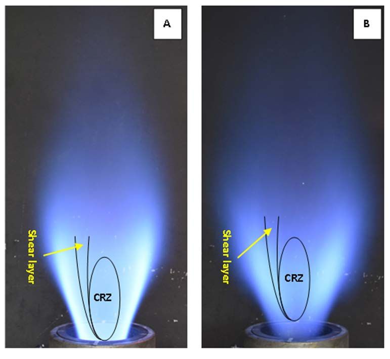
2210 F. A. Hatem et.al

 Fig. 5. LDA measurements depicted using Tecplot 360 EX 2015 R1,
 the differences in vorticity magnitude between bluff-body and axial air jets.

 Moreover, it seems that the dilution of swirling flame downstream due to air-
jet govern the density jump, and baroclinicity attenuates that can initiate shear layer
roll-up, consequently local instability around CRZ [20]. Figure 6 illustrates the
effect of air injection on the local mixture dilution and interaction between the CRZ
and shear layers, Fig. 6(a) represents the case of swirling combustion without axial
jets (no dilution) and Fig. 6(b) depicts the case when an axial air jet is introduced
to swirling flame, the dilution of swirling flames is obvious.
 It can also conclude that heat loss from the flame to the air jet results in flame
anchoring slightly downstream than that of the bluff-body case. Which, in turn,
lowering vorticity dilatation in the upstream region and allow the flame to
withstand in higher flow strain closer to the shear layer [13].
 Air injection position inside burner plenum for tangential inlets of the swirl
burner can alter the blow-off limits. Five vertical positions (Lo=0, 29, 75, 110 and
150 mm) of air-jet have been investigated. Figure 7 shows the effect, for the
baseline case Lo=0 mm, all blowoff limits were recorded at equivalence ratio
Φ⁓0.53, with a good range of inlet tangential velocity w=2.8-8 m/s. However stable
operation for low flow rates at this position is difficult to achieve due to
aerodynamic perturbations arise between air jet and tangential flow rate.
 The next three positions, Lo=29, 75 and 110 mm, the effect of aerodynamic
turbulence became more obvious, leading to a reduction in the range of inlet

Journal of Engineering Science and Technology June 2021, Vol. 16(3)
Experimental Investigation of the Effects of Bluff-Body Size and Axial Air. . . . 2211

tangential velocity w=2.5-7 m/s accompanied with a noticeable fluctuation of
equivalence ratio values. For Lo=150 mm, the air jet became coherent at this
position and less affected by turbulence, consequently, reveal wide range of inlet
tangential velocity values w=1.9-8 m/s.

 Fig. 6. Effect of axial air jets on the local mixture dilution and interaction
between CRZ and shear layers (a) without axial air jets no dilution; and (b) with
 axial air jets produces dilution of flame. Images were taken by Nikon D7200.

 Fig. 7. Effect of air injection position on blow-off limits.

 Thus, this position is considered as the optimum blow-off limits in terms of
wide stability operation margin, although some fluctuation of equivalence ratio
values at moderate inlet tangential velocity values w=4.5-6.

Journal of Engineering Science and Technology June 2021, Vol. 16(3)
2212 F. A. Hatem et.al

4. Conclusions
This study provides an experimental approach to study the effect of bluff-body size
and axial air jets on blow-off limits in premixed swirling flames. The first part of
this study revealed that the outside diameter of cylindrical bluff-body could
considerably alter blow-off limits. Small size bluff-body (λ =0.205) moves blow-
off limits to the leaner region with (Φ=4 to 4.2); the stability map became narrower
regarding inlet tangential velocities with (w=2.7 to 4.2), in other words, limited
burner output power. Moderate bluff-body size (λ = 0.345) can increase the range
of inlet tangential velocity range, almost 1 m/s higher than small size and it reveals
a considerable fluctuation in terms of equivalence ratio values. Bigger bluff-body
diameter (λ=0.378) produces the optimum operation, a reasonable range of inlet
tangential velocity values (w=2.5-3.5) accompanied with an almost steady increase
of equivalence in the range of (Φ=2.5-4.5).
 The second part of this work reveals that axial air jets can be employed successfully
in swirl burners to simulate bluff-body physically, hence perform the flame holding and
stabilization function. They can also control the flow field and flame-flow interaction
by altering the characteristics of coherent structures downstream. Wider operation
stability map revealed the feasibility of using this technique in industrial swirl
combustors, and it seems a promising technique to enable combustion systems to be
work with different blends, especially high hydrogen fuels. Axial air injection extends
blow-off limits to higher inlet tangential velocities range of (w=2-8 m/s) at almost
constant equivalence ratio (Φ=0.53), this range of inlet tangential velocity is almost
three times compare the bluff-body case, (w=2.5-4.5 m/s).
 The position of opening air-jet inside burner plenum plays important rule
regarding stability operation map and can alter blowoff limits. The base-line case
Lo=0 mm and Lo=150 mm revealed a wide range of inlet tangential velocity.
Nevertheless, for the base-line case, it is pretty difficult to achieve stable operation
at a low flow rate (low inlet tangential velocities) due to subjected to turbulence
arise from the clash between air-jet and tangential flow rate. Conversely, the
turbulence effect is not pronounced for Lo=150 mm position, as it opens slightly far
from the turbulence perturbations region, hence it is considered as the optimum
case. Other three positions show a narrower range of inlet tangential velocity with
an equivalence ratio fluctuation, the reason behind that is at these positions air jet
is opened at regions closer to tangential inlets of the burner; hence they are affected
by high aerodynamic perturbations at this region.

 Nomenclatures

 D The nozzle inside diameter, mm
 ID Internal diameter of tangential inlets, mm
 L0 Injector positions mm
 ̇ Air mass flowrate, kg/s
 ̇ Fuel mass flow rate, kg/s
 w Inlet tangential velocity, m/s
 Y Vertical distance downstream burner exit, mm
 Greek Symbols
 Φ Equivalence ratio
 λ The ratio between bluff-body diameter and nozzle inside diameter

Journal of Engineering Science and Technology June 2021, Vol. 16(3)
Experimental Investigation of the Effects of Bluff-Body Size and Axial Air. . . . 2213

 Abbreviations
 CRZ Central recirculation zone
 LDA Laser Doppler Anemometry
 LPM Litter per minute

References
1. Durbin, M.D.; and Ballal, D.R. (1996). Studies of lean blowout in a step swirl
 combustor. Journal of Engineering for Gas Turbines and Power, 118(1), 72-77.
2. Chaudhuri, S.; Kostka, S.; Renfro, M.W.; and Cetegen, B.M. (2010). Blow-off
 dynamics of bluff-body stabilised turbulent premixed flames. Journal of
 Combustion and Flame, 157(4), 790-802.
3. Kwong, W.Y.; and Steinberg, A.M. (2018). Blowoff and reattachment
 dynamics of a linear multinozzle combustor. Journal of Engineering for Gas
 Turbines and Power, 141(1), 11015(9 page).
4. Guo, S.; Wang, J.; Zhang, W.; Lin, B.; Wu, Y.; Yu, S.; Li, G.; Hu, Z.; and
 Huang, Z. (2019). Investigation on bluff-body and swirl stabilized flames near
 lean blowoff with PIV/PLIF measurements and LES modelling. Journal of
 Applied Thermal Engineering, 160, 114021.
5. Jiménez, C.; Michaels, D.; and Ghoniem, A.F. (2018). Stabilisation of ultra-lean
 hydrogen enriched inverted flames behind a bluff–body and the phenomenon of
 anomalous blow-off. Journal of Combustion and Flame, 191, 86-98.
6. Kedia, K.S.; and Ghoniem, A.F. (2015). The blow-off mechanism of a bluff-
 body stabilised laminar premixed flame. Journal of Combustion and Flame,
 162(4), 1304-1315.
7. Chowdhury, B.R.; and Cetegen, B.M. (2018). Effects of free stream flow
 turbulence on blowoff characteristics of bluff-body stabilized premixed
 flames. Journal of Combustion and Flame, 190, 302-316.
8. Rashwan, S.S.; Ibrahim, A.H.; Abou-Arab, T.W.; Nemitallah, M.A.; and
 Habib, M.A. (2016). Experimental investigation of partially premixed
 methane-air and methane-oxygen flames stabilized over a perforated-plate
 burner. Journal of Applied Energy, 169, 126-137.
9. Wu, B.; Zhao, X.; Chowdhury, B. R.; Cetegen, B. M.; Xu, C.; and Lu, T.
 (2019). A numerical investigation of the flame structure and blowoff
 characteristics of a bluff-body stabilized turbulent premixed flame. Journal of
 Combustion and Flame, 202, 376-393.
10. Shanbhogue, S.J.; Husain, S.; and Lieuwen, T. (2009), Lean blow-off of bluff
 body stabilized flames: Scaling and dynamics. Progress in Energy and
 Combustion Science. 35(1), 98-120.
11. Lefebvre, A.H.; and Ballal, D.R. (2010). Gas turbine combustion: alternative
 fuels and emissions (3rd edition). New York: CRC Press.
12. Ebrahimi, H. (2006). Overview of gas turbine augmentor design, operation,
 and combustion oscillation. 42nd AIAA/ASME/SAE/ASEE Joint Propulsion
 Conference and Exhibit. California, USA, 1-16
13. Michaels, D; and Ghoniem, A.F. (2016). Impact of the bluff-body material on
 the flame leading edge structure and flame–flow interaction of premixed
 CH4/air flames. Journal of Combustion and Flame, 172, 62-78.

Journal of Engineering Science and Technology June 2021, Vol. 16(3)
2214 F. A. Hatem et.al

14. Emerson, B.; O’Connor, J.; Juniper, M.; and Lieuwen, T. (2012). Density ratio
 effects on reacting bluff-body flow field characteristics. Journal of
 Fluid Mechanics, 706, 219-250.
15. Chen, Z.; Shen, L.; and Wen, C.Y. (2019). Flow control on a bluff body using
 dielectric barrier discharge plasma actuators. AIAA Journal, 57(3), 1-5.
16. Longwell, J.P.; Chenevey, J.E.; Clark, W.W.; and Frost, E.E. (1948). Flame
 stabilisation by baffles in a high velocity gas stream. Symposium on
 Combustion and Flame, and Explosion Phenomena, 3(1), 40-44.
17. Wright, F.H. (1959). Bluff-body flame stabilization: Blockage effects. Journal
 of Combustion and Flame, 3, 319-337.
18. Hertzberg, J.R.; Shepherd, I.G.; and Talbot, L. (1991). Vortex shedding behind
 rod stabilized flames. Journal of Combustion and Flame, 86(1-2), 1-11.
19. Nair, S; and Lieuwen, T.C. (2007). Near-blowoff dynamics of a bluff-body
 stabilized flame. Journal of Propulsion and Power, 23(2), 421-427.
20. Chaudhuri, S; and Cetegen, B.M. (2008). Blowoff characteristics of bluff-body
 stabilized conical premixed flames with upstream spatial mixture gradients and
 velocity oscillations. Journal of Combustion and Flame, 153(4), 616-633.
21. Dawson, J.R.; Gordon, R.L.; Kariuki, J.; Mastorakos, E.; Masri, A.R.; and Juddoo,
 M. (2011). Visualization of blow-off events in bluff-body stabilized turbulent
 premixed flames. Proceedings of Combustion Institute, 33(1), 1559-1566.
22. Plee, S.L; and Mellor, A.M. (1979). Characteristic time correlation for lean
 blowoff of bluff-body-stabilized flames Journal of Combustion and Flame, 35,
 61-80.
23. Yamaguchi, S.; Ohiwa, N.; and Hasegawa, T. (1985). Structure and blow-off
 mechanism of rod-stabilized premixed flame. Journal of Combustion and
 Flame, 62(1), 31-41.
24. Hatem, F.A.; Alsaegh, A.S.; Al-Faham, M.; Valera-Medina, A.; Chong, C.T.;
 and Hassoni, S.M. (2018). Enhancing flame flashback resistance against
 Combustion Induced Vortex Breakdown and Boundary Layer Flashback in
 swirl burners. Journal of Applied Energy, 230, 946-959.
25. Syred, N.; Abdulsada, M.; Griffiths, A.; O’Doherty, T.; and Bowen, P. (2012).
 The effect of hydrogen containing fuel blends upon flashback in swirl burners.
 Journal of Applied Energy, 89(1), 106-110.
26. Syred, N.; Giles, A.; Lewis, J., Abdulsada, M.; Valera Medina, A.; Marsh, R.;
 Bowen P.J; and Griffiths, A.J. (2014). Effect of inlet and outlet configurations
 on blow-off and flashback with premixed combustion for methane and a high
 hydrogen content fuel in a generic swirl burner. Journal of Applied Energy,
 116, 288-296.
27. Valera-Medina, A.; Syred, N.; Kay, P.; and Griffiths, A. (2011). Central
 recirculation zone analysis in an unconfined tangential swirl burner with varying
 degrees of premixing. Journal of Experiments in Fluids, 50(6), 1611-1623.
28. Abdulsada, M.; Syred, N.; Bowen, P.; O'Doherty, T.; Griffiths, A.; Marsh, R.;
 and Crayford, A. (2012). Effect of exhaust confinement and fuel type upon the
 blow-off limits and fuel switching ability of swirl combustors. Journal of
 Applied Thermal Engineering, 48, 426-435.

Journal of Engineering Science and Technology June 2021, Vol. 16(3)
You can also read